

Page 1
Install/Connect the Hardware
Quick Start Guide
Install/Run Vlinx Manager
Configure the Serial Server
General Setup
Enter a name for the serial server. This name will
show up in the serial server list in Vlinx Manager.
Change the login password if desired.
Enter The Network Settings
The serial server is configured at the factory to get an
IP address automatically (DHCP). If a DHCP server is
not available on your network, it will default to
169.254.102.39.
If a static IP is desired, uncheck the box “I want
DHCP to setup the network”. Enter the static IP,
Subnet Mask, and default Gateway information.
Setup the Serial Port Communications
For each serial port on the device: Select the
communications mode – RS-232, RS-422, RS-485
(2-wire), RS-485 (4-wire)
Select the communicationsparameters (Baud Rate,
Data Bits, Stop Bits, Parity and Flow Control) for your
serial device
Setup the Serial Port Network Protocol
Select the type of network protocol you want to use
for each port: TCP, UDP, VCOM or Paired Mode.
TCP: select whether the serial server will operate as
a Client or Server, then configure the required IP
address, port numbers and other related parameters.
UDP: configure the IP addresses, ports and other
related parameters for the devices you want to
receive data from and send data to.
VCOM:configure the serial port to act as a virtual
COM port on the PC. You must also add the VCOM
driver to the PC using the “Add” button in Vlinx
Manager.
Paired Mode:configure the serial server to be paired
with another serial server, configure it as either the
client or the server in the pair and set up the IP
address, port numbers,etc.
Setup Advanced parameters as necessary for your
applicationClick on the “Advanced” button to setup
serial and network timers and packet delimiters.
Save your configuration to the serial server
The device will re-boot after saving the settings.
2
Mount the serial server using panel or DIN rail mount
adapters.
Connect a 10 to 58 VDC power supply (6.0 W required).
Connect to the network (using a standard Ethernet cable or
fiber-optic cable):
Connect the serial device (using the appropriate cable for
your model):
RS-232 with DB9: straight-through for DCE device, null
modem for DTE device
RS-232/422/485 with terminal blocks
Install Vlinx Manager
Insert the Vlinx manager software CD into the computer.
The install program should automatically run.
Follow the prompts to install the software
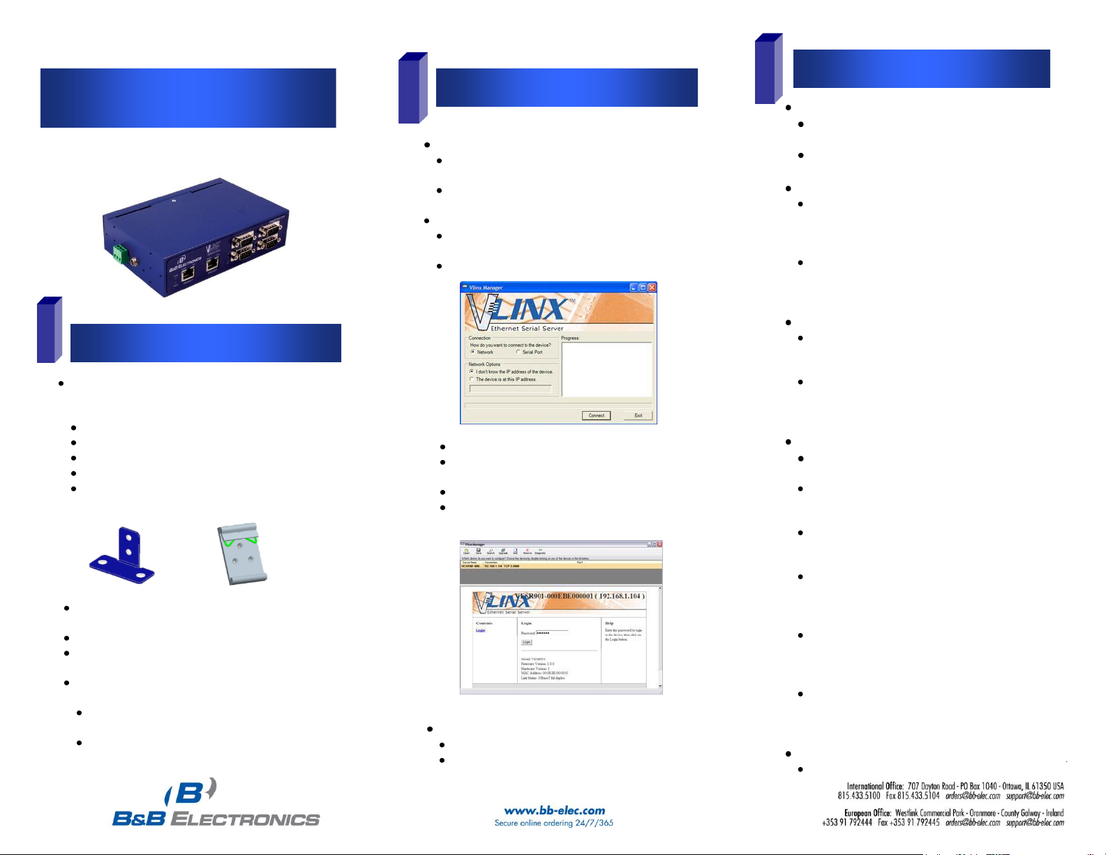
RunVlinx Manager:
ClickStart>Programs>B&BElectronics>Vlinx>Vlinx
Manager>VESRSerial Server
The Discovery page opens
Select Network.
If you know the IP address, select:“The device is at this
address”, and type in the address.
If not,select “I don’t know the IP address of the device”.
Click on the Connect button. Vlinx Manager will search
for any serial servers on the network.
Login to the Serial Server
Select the serial server from the list.
Login to the device. (factory password is blank. Just
click Login). The General setup page will appear.
Unpack your serial server from the shipping container.
Verify that all included items are present.
VlinxVESR4x4 module
CD with Vlinx Manager software and user’s manual
(2) Panel mount adapters and (4) mounting screws
DIN rail mount adapter and (3) mounting screws
This quickstart guide
1
3
Model: VESR4x4
PN9036R1_VESR4x4 _0712qsg
P#xxxx_Vlinx_VESR4x4_Serial Server_2511qsg
Page 2
Set up serial server as a TCP Server on serial port 1.
Set serial port to RS-232 on serial port 1.
Set to 9600 8-N-1 on serial port 1.
Loopback serial port 1 by connecting TD to RD.
Open a command window and type “telnet x.x.x.xyyyy”
where x.x.x.x is the IP address of the serial server and
yyyy is the port number of the serial port.
Type characters on the keyboard. The characters
should appear in the window. If not, double check your
settings.
Test and Verify Operation
LED Status Indicators
Reset Switch Operation
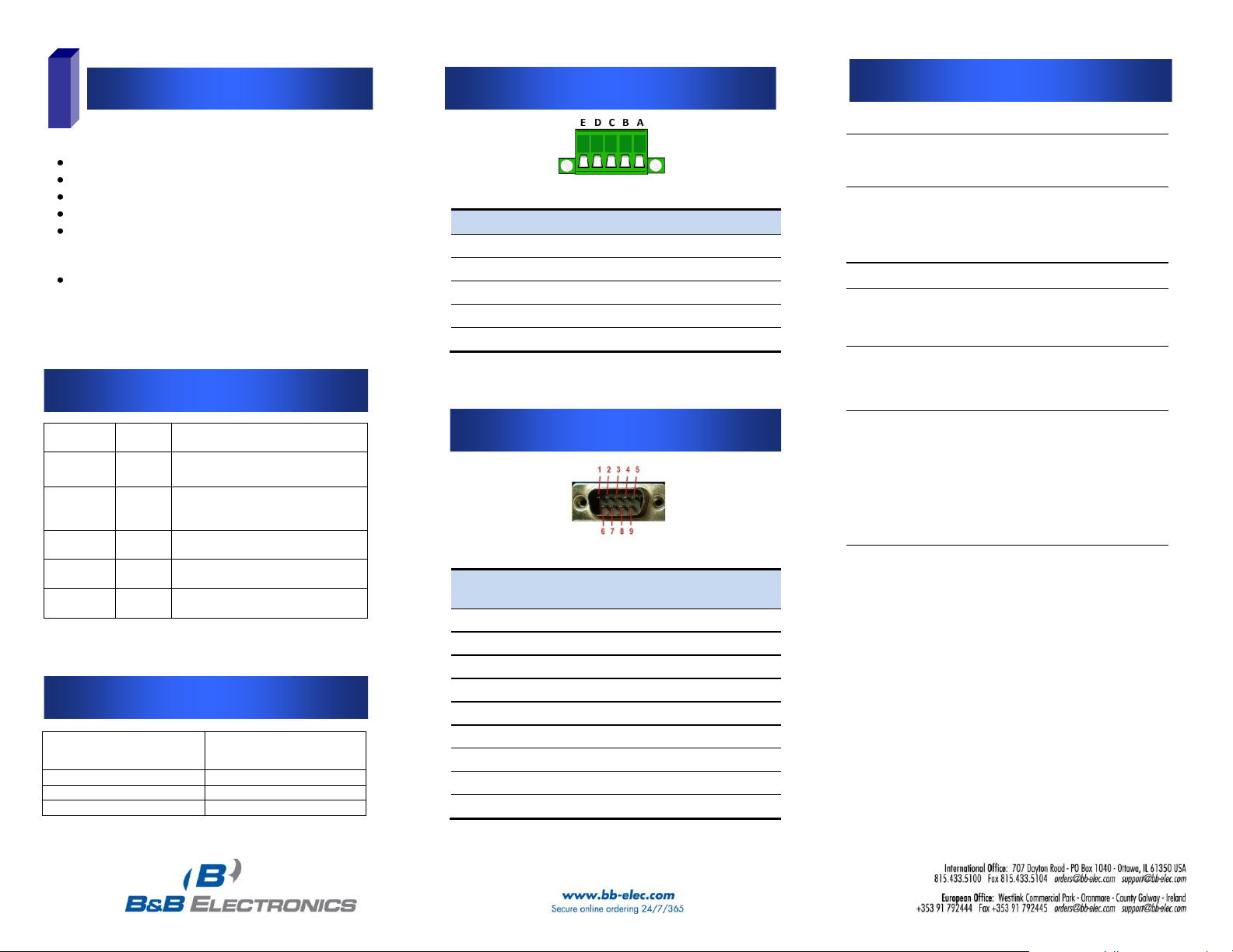
Serial Port Pinout - DB-9
Serial Port Pinout – Terminal Blk
Specificationsd
4
Power Supply
Voltage
Requirements
10 to 58 VDC
Power Consumption
6.0 watts maximum
Environment
Operating
Temperature
-40 to 80 °C (-40 to 176 °F)
Storage Temperature
-40 to 85 °C (-40 to 185 °F)
Operating Humidity
10 to 95% non-condensing
Maximum Ambient
Surrounding Air Temp
80 °C
Certifications
FCC
Part 15 Class A
CE
NEMA TS2
Enclosure
Rating
IP30
Mounting
DIN rail mount (35 mm)
Dimensions
(VESR4x4)
1.8 x 4.4 x 6.75 in (4.57 x 12.2
x 17.1 cm)
Terminal
Blocks
Wire Size
28 to 16 AWG
Wire Type
Copper Wire Only
Tightening Torque
5 KG-CM
Wire Temp Rating
105 °C Minimum
Sized for 60 °C Ampacity
Note:
One Conductor Per Terminal
LED
Color
Status
Power
Green
On =Power connected
Ready
Green
On = Initialization
Flashing Slowly = Normal Operation
Flashing Quickly = Device Re-booting
Speed
Yellow
On = 100Mbps
Off = 10Mbps
Link
Green
On = Ethernet Connected
Flashing = Data TX/RX
Serial Ports
1, 2, 3, 4
Green
On = Serial Port Open
Flashing = Data TX/RX
Hold in Reset (mode) switch
for…
Result
0 to 2 seconds
Initiates a Hardware Reset
2 to 10 seconds
Enters Console Mode
More than 10 seconds
Resets to Factory Defaults
Terminal
RS-232
RS-422
RS-485
A
RTS
TDA(-)
Data A (-)
B
TD
TDB(+)
Data B (+)
C
CTS
RDA(-)
---
D
RD
RDB(+)
---
E
GND
GND
GND
Terminal
RS-232
RS-422/RS-485
4-wire
RS-485 2-wire
1
DCD
RDA(-)
---
2
RD
RDB(+)
---
3
TD
TDB (+)
Data B (+)
4
DTR
TDA (-)
Data A (-)
5
GND
GND
GND
6
DSR
---
---
7
RTS
---
---
8
CTS
---
---
9
---
---
---
 Loading...