

Page 1
Product Overview
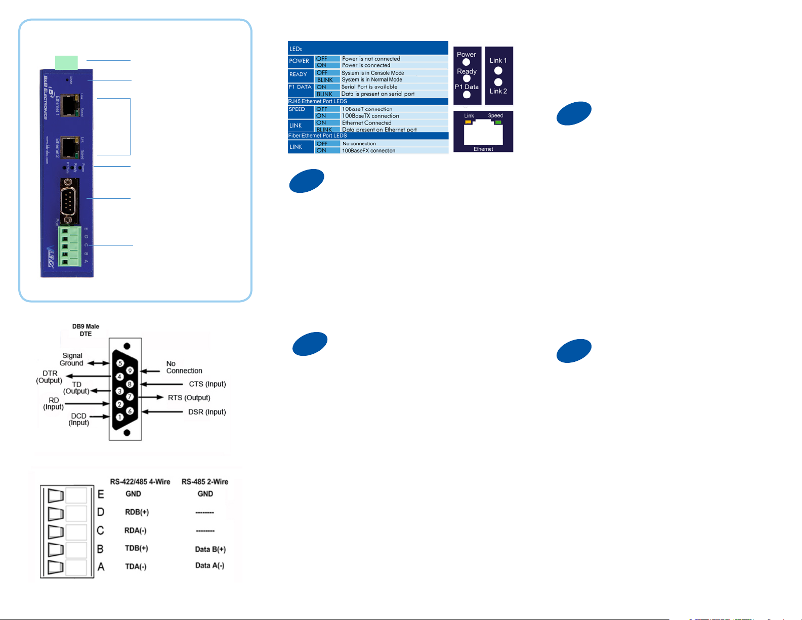
Power 10 - 48 VDC
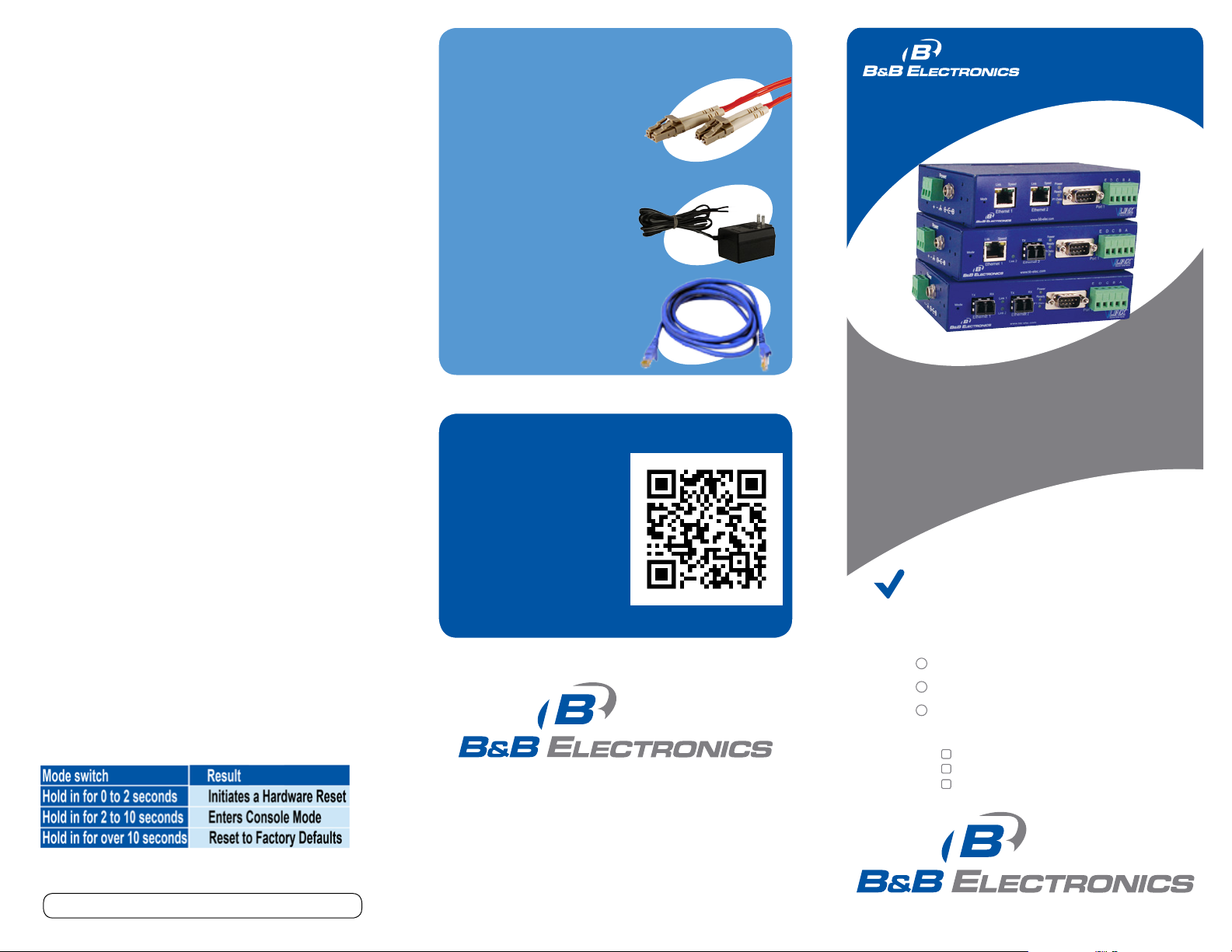
Mode Switch
5. Click “Login”. Password is blank from factory.
No password is necessary to operate the VESR
unit. The Conguration/General page appears.
Fiber/Ethernet Ports
LEDs
Male DB9 Port
Te rminal B lo ck Port
1
1. Power the device.
2. Connect an RJ45 or optical connector
to a network drop using a standard network
cable. (The RJ45 ports on the model shown are
interchangeable. One may used for pass-through
Ethernet.)
3. Connect the Serial Device(s).
RS-232 with DB9: straight-through for DCE
device. Null modem for DTE device.
RS-422/485 with terminal blocks.
2
1. Use included CD to install Vlinx Serial Server
Manager. If Autorun does not start, go to “My
Computer” and select the CD drive. You will see
a Vlinx VESR icon. Double-click it to launch the
installation.
2. To open Vlinx Serial Server Manager: click Start/
Programs/B&B Electronics/Vlinx/Vlinx Serial Server
Manager/Serial Server Manager. If the device does
not connect, cycle (unplug-replug) the power, then try
again.
3. To congure via the network, select “Network”.
4. If you know the IP address, select “The device is
at this address,” and type in the IP address. If not,
select “I don’t know the IP address of the device.” Click
Connect.
(Alternative Method: Open a web browser and type
the IP address of the Serial Server in the Address Bar.
When the Serial Server is found the Login window will
appear.)
Set Up Hardware
Install/Setup
3
“I want DHCP” is preselected to set up the network
using dynamic IP addressing. The Gateway is set
up at the factory to receive an IP assignment from a
DHCP Server.
1. If a DHCP Server is not available on your network,
it will default to 169.254.102.39.
2. If a DHCP server is not available and the default
address does not work on your PC, change your
PC network settings to IP Address: 169.254.102.1,
Subnet Mask: 255.255.0.0, Default Gateway:
169.25 4.102.100 .
If you are not able to use these settings in your
installation, refer to the User’s Manual for directions to
change the Serial Server’s TCP/IP settings.
4
1. Port Settings: Four congurations are available:
TCP, UDP, VCOM Mode and Paired Mode. TCP
is the most common choice, and will be briey
described below. (Paired Mode uses the same settings
as TCP.) Detailed information about UDP and VCOM
Mode may be found in the User’s Manual.
2. TCP Port Settings:
-- Choose “TCP”.
-- Choose either “server” or “client.”
-- Enter the port number on which you
want to “wait for connections.”
-- Enter the maximum number of desired
connections.
-- Specify who is permitted to connect.
Set Up Network
Setting Up Your Device
Page 2
Troubleshooting
The primary check for correct operation is the
device LEDs.
For advanced information, see the Conguration
Manager menu, at the top of Vlinx Serial Server
Manager screen.
Recommended Accessories
and Power Supplies
PS12BVLB-INT-MED
Power Supply
http://www.bb-elec.PS12BVLB-INT-MED
DFMM- LCLC
G
Q
S
uick
tart
uide
Select Diagnostic for a check of communications
status with attached VESR321 device, and then
select the device for which the communications
check is desired. A report of reply times and
ping statistics is generated and can be saved.
Note that you can send your conguration les
to B&B Tech Support for review.
DFMM-LCLC
Fiber Cable
http://search.bb-elec.com/?s=PPC_
GUIDE&q= DFMM-LCLC
Ethernet Cables
http://search.bb-elec.com/?q=
ethernet+cable
Fast East Answers
You can use your
smart phone to
access complete
documentation
on our website. Simply
scan the code to the
right.
1-888-948-2248 | Europe: +353 91 792444
www.bb-elec.com
VESR321
Isolated Industrial
Ethernet to Serial Servers
First Things First...
Before you begin, be sure you have
the following:
VESR321
CD with software and manuals
Mounting accessories kit
Additional items required but not included:
Ethernet cable(s)
Null modem cable(s)
Power Supply for terminal block
or barrel connector
Document number – pn9758_VESR321-xx_r0_4212_qsg
707 Dayton Road | PO Box 1040 | Ottawa, IL 61350
Phone: 815-433-5100 | Fax: 815-433-5109
www.bb-elec.com | E-mail: info@bb-elec.com
© 2012 B&B Electronics Manufacturing Company
Fast and easy on the web:
www.bb-elec.com
Page 3

5
Note: The Vlinx Serial Server Manager
software contains default parameter values
that are common to most Modbus networks.
1. Change the Description of the serial port if
needed.
2. Set the Mode to RS-232, RS-422 (4 wire),
RS-485 (2 wire) or RS-485 (4 wire).
3. Set the Baud Rate to control the speed of the port.
Valid rates range between 75 and 230.4k bits per
second.
4. Stop Bits controls the number of bits for end of
character.
5. Parity controls the error checking mode, with
options of No Parity, Odd, Even, Mark and Space.
Set Up Serial Port
Recommended Accessories
and Power Supplies
VESR321
G
Q
S
uick
tart
uide
5
There are additional conguration pages that may be
accessed by selecting “Next” at the bottom of each
page, or by selecting the desired page from the
vertical list in the left-hand column.
The Vlinx Serial Server Manager defaults to options
like “Network” and “I don’t know the IP of the
device.” If the defaults meet your needs you don’t
need to set or change them.
If you have completed the conguration, click Save to
save the conguration to the serial server. Allow 15
seconds for the Serial Server to reboot.
Click “Connect.” You should see a list of all
devices on the network, including your new
device. If you do not see your new device,
please refer to the Troubleshooting tips.
You may now log out.
Finish and Log Out
Isolated Industrial
Ethernet to Serial Servers
Document number – pn9758_VESR321-xx_r0_4212_qsg
 Loading...