

Page 1
User Manual
U
U
LII
L
N
X
N
X
2 & 4 Port USB Isolated Serial Converters
U
U
S
S
U
U
R
R
S
S
6
6
R
R
0
0
6
6
2
2
0
0
&
&
4
4
Page 2

USR60x Series
Documentation Number:USR60x-2112m
This product was designed and manufactured in Ottawa, Illinois USA
using domestic and imported parts by:
International Headquarters:
707 Dayton Road
Ottawa, IL 61350 USA
Phone: (815) 433-5100
Website: www.bb-elec.com
European Headquarters:
Westlink Commercial Park
Oranmore, Co. Galway, Ireland
Phone: (+353) 91-792444
Website: www.bb-europe.com
Original – April 2011
©2011 No part of this publication may be reproduc ed or transmitted in any form or by any means, electronic or mechani cal, including photography, rec ording, or
any information storage and retrieval system without written consent. Information in this manual is subject to change without notice, and does not represent a
commitment on the part .
B&B Electro nics Manufact uring shall not be liable for incidental or consequential dama ges resulting from the furnishing, performance, or use of this manual.
All brand names used in thi s manual are t he registered trademarks of their resp ective owners . The use of trademarks or other designations in this publication is
for referenc e purposes onl y and does not constitute an endorsement by the trademark holder.
This document was created using Author-it, Microsoft Word, Adobe Acrobat, Snag It and other software.
Page 3

Table of Contents
User Manual ................................................................................................ 1
Ulinx USR602 & USR604 .............................................................................. 1
Overview ..................................................................................................... 5
Safety .............................................................................................................. 6
Product Feature Summary .................................................................................. 6
About this Manual .............................................................................................. 6
Product Information .................................................................................... 7
USR60x Models ................................................................................................. 7
Package Contents .............................................................................................. 7
Typical Applications / Modes of Opera tion ............................................................. 8
Quick Start Guide ........................................................................................ 9
Software Installation ................................................................................ 13
Installing the Driver .......................................................................................... 13
Un-Installing the Driver ..................................................................................... 16
Hardware Installation ............................................................................... 17
Installing and Mounting the USR60x.................................................................... 18
Connecting Power ............................................................................................. 18
Connecting to a PC ........................................................................................... 19
Connecting to the Serial Ports ............................................................................ 20
Termination and Bias ing .................................................................................... 21
Setting COM Port Operating Modes ..................................................................... 21
LED Indicators .................................................................................................. 23
Advanced User Settings ............................................................................. 25
Setting Serial Port Properties ............................................................................. 26
Advanced Settings in Device Manager ................................................................. 27
Modbus Basics .................................................................................................. 30
Specifications ............................................................................................ 31
Product Specifications ....................................................................................... 32
Certifications .................................................................................................... 33
Default Settings ............................................................................................... 34
Page 3 of 45 Document Number: USR60x-0812m
www.bb-elec.com/
www.bb-europe.com/
Page 4

USR602 Dimensions .......................................................................................... 35
USR604 Dimensions .......................................................................................... 36
Panel Mount Dimensions .................................................................................... 37
Appendix ................................................................................................... 39
Loopback Test .................................................................................................. 39
Serial Port Wiring ............................................................................................. 42
Index ........................................................................................................ 45
Page 4 of 45 Document Number: USR60x-0812m
www.bb-elec.com/
www.bb-europe.com/
Page 5
Section 1 - Overview
......
..........
.....................
SECTION 1
Overview
In This Section
Safety ................................................................
Product Feature Summary ................................
About this Manual ................................
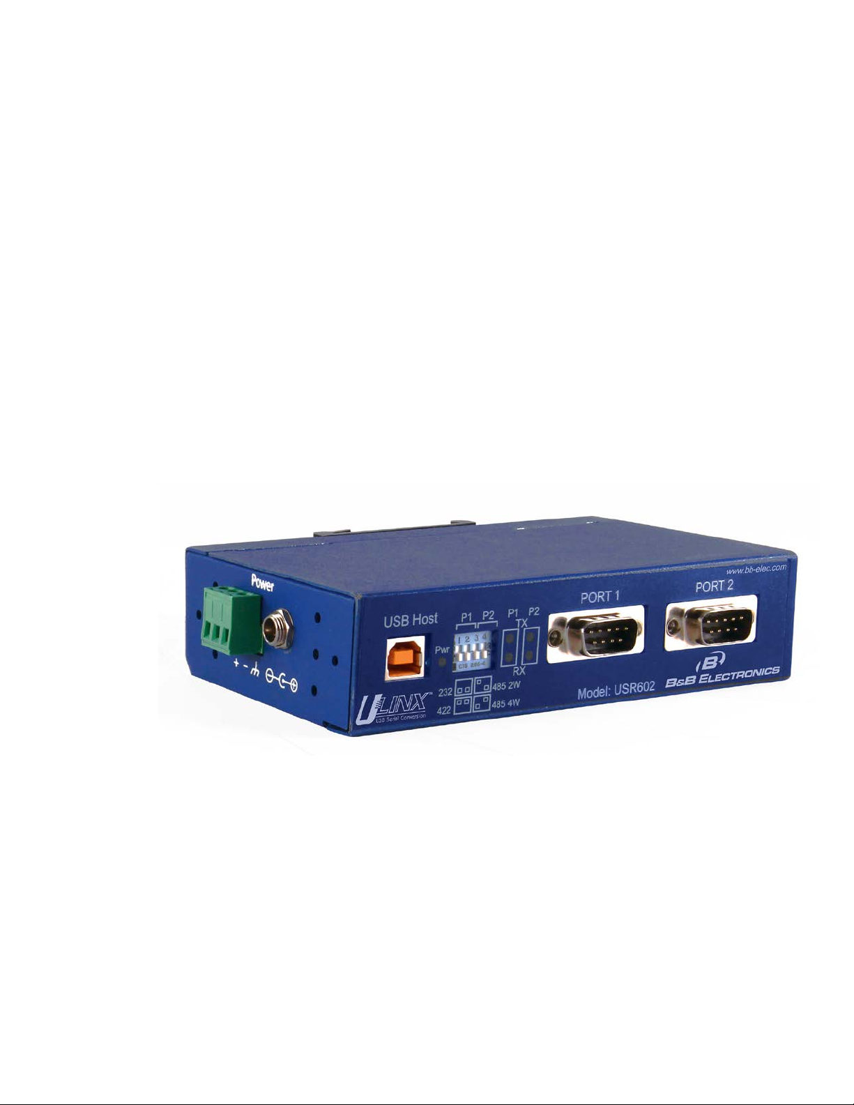
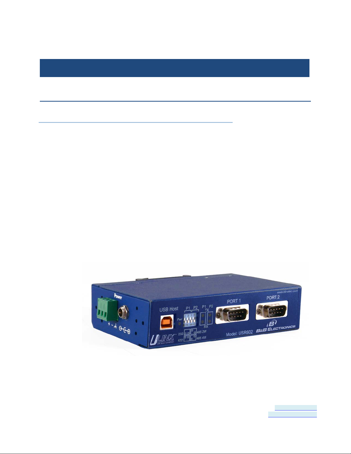
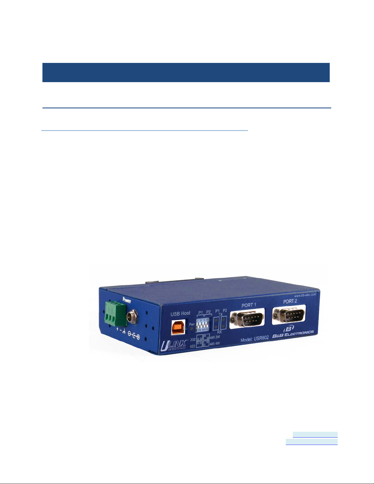
The USR60x family of products are industrial grade isolated USB to
serial converters. They enable any host USB port to provide multiple
RS-232, RS-422 or RS-485 two or four-wire serial interfaces. The
USR602 provides two ports; the USR604 provides four ports.
USR60x converters support USB 2.0 high speed data rates of 480
Mbps. The upstream and downstream sections are isolated to 2000
volts. Industrial features such as a rugged metal case, versatile
mounting options, high ESD protection, wide temperature ranges, and
high retention USB connectors set these devices apart from other USB
to serial converters.
Figure 1: USR602 USB to Serial Converter
Page 5 of 45 Document Number: USR60x-2112m
www.bb-elec.com/
www.bb-europe.com/
Page 6

Section 1 - Overview
Safety
All safety related regulations, local codes and instruct ions that appear
in the literature or on equipment must be observed to ensure personal
safety and to prevent damage to either the instrument or equipment
connected to it. If equipment is used in a manner not specified by the
manufacturer, the protection provided by the equipment may be
impaired.
Product Feature S ummary
• Easy to install
• 2 kV port to port isolation
• High retention USB connector
• Rugged metal case
• DIN rail or panel mount options included
• 8 kV contact, 15 kV air ESD surge protection
• Wide temperature range (-40 to 80° C)
• USB 2.0 and 1.1 compatible
• LEDs indicate power and port status
• Includes 2 meter USB cable
• USB powered (USR602 only) or ext ernally powered
• Redundant power inputs (10 to 48 VDC) via terminal block or
locking barrel jack
• Drivers for Windows 2000 and up (including 64 bit variants)
• RS-232, RS-422, RS-485 two-wire and RS-485 four-w ire interface s
• Modbus support
• 2 or 4 port models
About this Manual
The content of this manual has been designed to be used by personnel
who have a basic understanding of computer systems and peripherals,
data communications, serial communications protocols (RS232/422/485), and basic electronics.
Page 6 of 45 Document Number: USR60x-2112m
www.bb-elec.com/
www.bb-europe.com/
Page 7

Section 2 - Product Information
.........................
......................
...................
SECTION 2
Product Information
In This Section
USR60x Models ................................
Package Contents ................................
Typical Applications / Modes of Operation
.
USR60x Models
The USR60x is a family of USB to serial converters. Models currently
available include:
• USR602 - Two Port Isolated USB to Serial Converter
• USR604 - Four Port Isolated USB to Serial Converter
Package Contents
• USR602 or USR604 Isolated USB to Serial Converter
• Driver CD
• 2 meter USB cable
• Panel mount adapters
• DIN rail mount adapter
• Quick start guide
Page 7 of 45 Document Number: USR60x-0812m
www.bb-elec.com/
www.bb-europe.com/
Page 8

Section 2 - Product Information
Typical Applications / Mo des of Operation
• Addition of serial ports to PCs
• Conversion of USB serial connecti on to:
• RS-232
• RS-422
• RS-485 two-wire
• RS-485 four-wire
Page 8 of 45 Document Number: USR60x-0812m
www.bb-elec.com/
www.bb-europe.com/
Page 9

Section 3 - Quick Start Guide
SECTION 3
Quick Start Guide
The following Quick Start Guide outlines the basic steps to get your
USR60x Converter up and running:
1. Check for included items
• 2 or 4 port industrial USB to serial converter
• Two meter USB cable
• Panel mount adapters
• DIN rail mount adapter
• Driver CD
• This quick start guide
2. Install the driver software (see "Installing the Driver" on page 13)
• The CD contains a driver installat ion program. Install the drivers
before connecting the converter to your PC.
• Put CD into drive. The installation program should launch
automatically.
• Follow the prompts
3. Mount the converter (DIN rail or panel mount)
• DIN Rail
• Locate DIN rail kit
• Mount on back of converter using screws
• Clip to a DIN rail
• Panel mount:
• Locate the panel mount kit
• Mount brackets to converter using screws
• Mount in panel
4. Connect power (see "Connecting Power" on page 18):
• USR602: Plug USB cable from PC into converter
Page 9 of 45 Document Number: USR60x-0812m
www.bb-elec.com/
www.bb-europe.com/
Page 10

Section 3 - Quick Start Guide
• USR604: Connect 10 to 48VDC to terminal block and/or barrel
jack
5. Check LED Indicators (on page 23)
• Power indicated by green Pwr LED
• Tx and Rx LEDs will indicate when data present
6. Set up the COM Port operating modes (see "Setting COM Port
Operating Modes" on page 21)
• Configure the DIP switches for each port to select one of the
following:
• RS-232 (Both DIP switches Off)
• RS-422 (Both DIP switches On)
• RS-485 4-wire (SW1 Off, SW2 On)
• RS-485 2-wire (SW1 On, SW2 Off)
7. Connect the serial ports (see "Connecting to the Serial Ports" on
page 20):
• Connect from the DB-9M connectors on the converter to your
devices or network:
• To connect to an RS-232 DTE device, use a null modem
(crossover) cable
• To connect to an RS-485 two-wire network, refer to RS-485
Two-Wire Connections (on page 43)
• To connector an RS-422 device, or an RS-485 four-wire
network, refer to RS-422 and RS-485 Four-Wire Connections
(on page 44)
8. Configure the serial ports (see "Advanced Settings in Device
Manager" on page 27)
• On the PC screen, open the Control Panel.
• Click System to open the Device Manager
• Under Ports, double-click the port to be configured.
• On the Serial Port Properties window, set the required
communications parameters of system with which you are
communicating.
• If necessary, click Advance d and set up the Advanced Properties
(refer to manual for information)
Page 10 of 45 Document Number: USR60x-0812m
www.bb-elec.com/
www.bb-europe.com/
Page 11

Section 3 - Quick Start Guide
9. Perform a loopback test to verify that the converter is working.
• Refer to the Loopback Test (on page 39) section
Page 11 of 45 Document Number: USR60x-0812m
www.bb-elec.com/
www.bb-europe.com/
Page 12

Page 13
Section 4 - Software Installation
...................
..............
SECTION 4
Software Installation
In This Section
Installing the Driver ................................
Un-Installing the Driver ................................
.
Do not connect the converter to your PC until the Driver is
installed. The driver is contained on the CD included with the
converter. It is installed using an executable program. This program
must be run on your PC before connecting the co nverter to your USB
port.
Installing the Driver
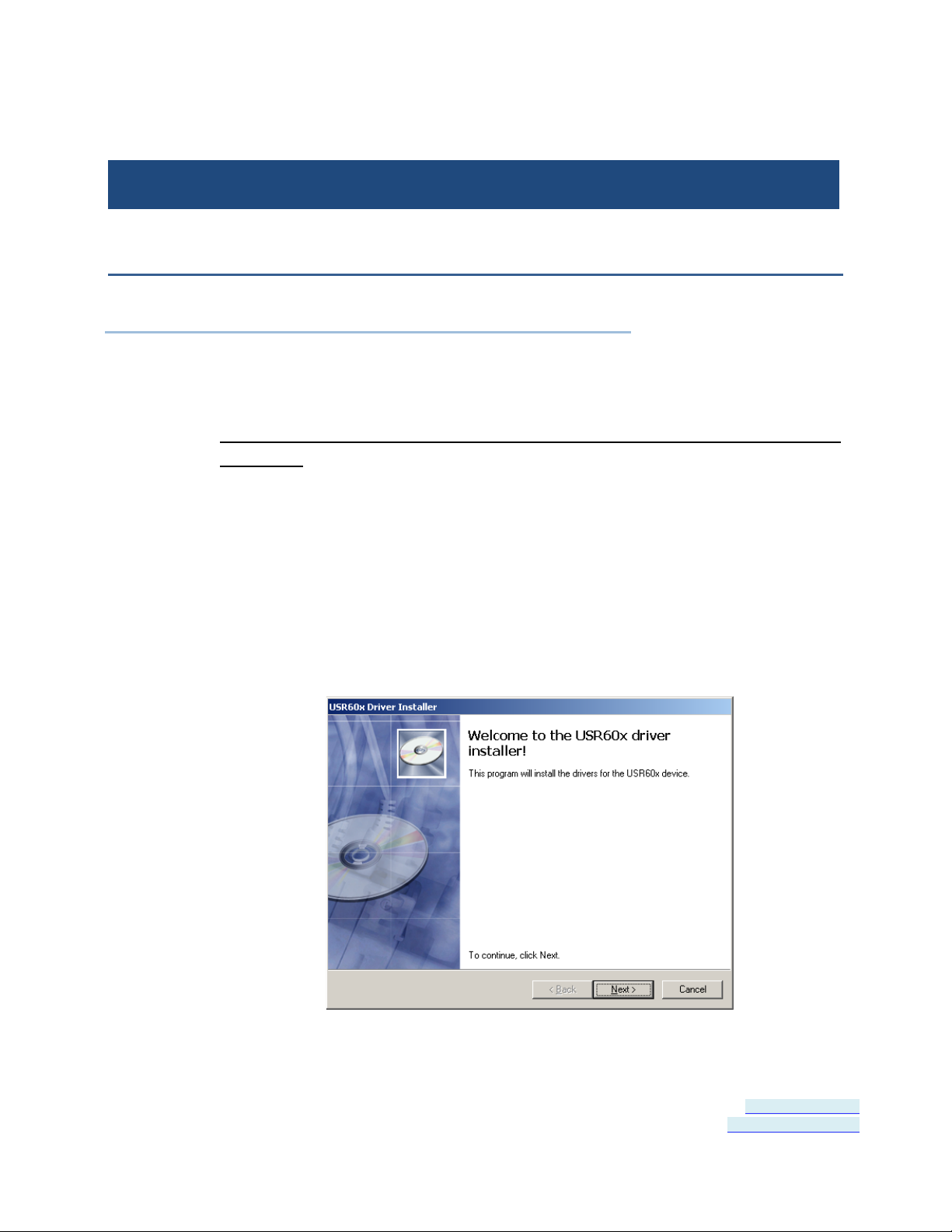
Insert the CD into your CD ROM Drive. The driver installation software
should automatically start. If not, browse the CD and double click on
the “setup.exe” file. The following dialog box will appear.
Figure 2: Run setup.exe dialog
Page 13 of 45 Document Number: USR60x-0812m
www.bb-elec.com/
www.bb-europe.com/
Page 14
Section 4 - Software Installation
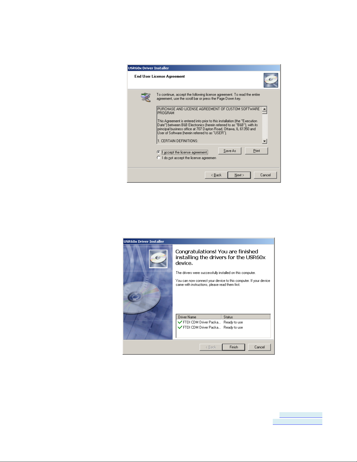
1. Click Next. The license agreement dialog box will appear.
Figure 3: End User License Agreement
2. Click Next. The program will install the drivers on your computer
and the installation complete screen will appear.
Figure 4: Installation Complete Screen
Page 14 of 45 Document Number: USR60x-0812m
www.bb-elec.com/
www.bb-europe.com/
Page 15

Section 4 - Software Installation
3. When the insta llation is complete you can plug in the USB to Serial
Converter. When you do this, the COM ports will be assigned. It
may take up to 30 seconds to make the COM port assignments the
first time you plug in the converter.
4. The driver software is now installed.
5. To verify that the communication port has been configured:
a. Open the Control Panel
b. Click System to open the System Properties dialog box.
c. Select the Hardware tab.
d. Click Device Manager to open the Device Manager dialog box.
e. Expand Ports (COM & LPT)
USB Isolated Serial Port should be listed as one of the COM
ports.
Page 15 of 45 Document Number: USR60x-0812m
www.bb-elec.com/
www.bb-europe.com/
Page 16
Section 4 - Software Installation
Un-I nstalling the Driver
To un-install the driver for the USR60x converter:
1. Open the Control Panel
2. Click System to open the System Properties dialog box.
3. Select the Hardware tab.
4. Click Device Manager to open the Device Manager dialog box.
5. Expand Ports (COM & LPT)
USB Isolated Serial Port should be listed as one of the COM ports.
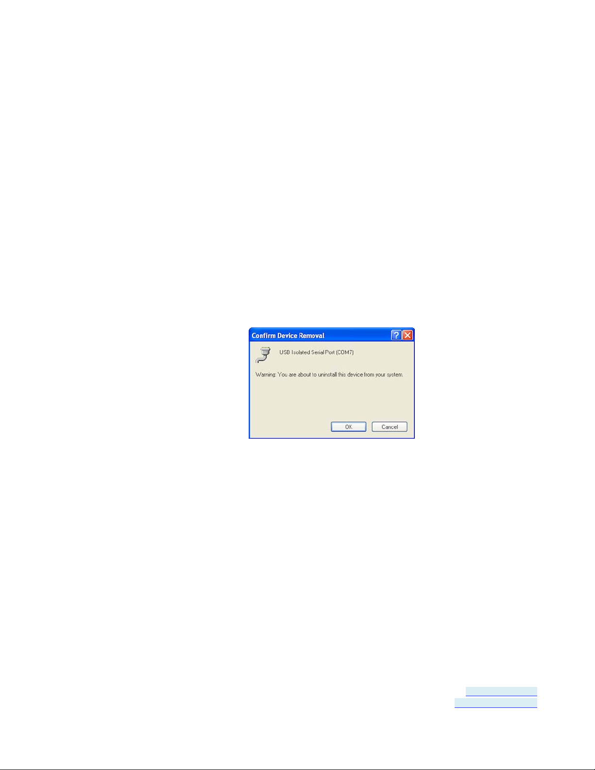
6. Right-click the COM port listing for the converter (USB Isolated
Serial Port)
The following dialog box appears.
7. Click OK.
The Com port listing for the converter disappears.
Page 16 of 45 Document Number: USR60x-0812m
www.bb-elec.com/
www.bb-europe.com/
Page 17
Section 5 - Hardware Installation
...........................
.....................
....................
....
............
.............................
..........................
SECTION 5
Hardware Installation
In This Section
Installing and Mounting the USR60x
Connecting Power ................................
Connecting to a PC ................................
Connecting to the Serial Ports ................................
Termination and Biasing ................................
Setting COM Port Operating Modes
LED Indicators ................................
Hardware installation includes mounting the device, connecting power,
connecting to a PC, connecting to serial devices and configuring the
serial ports. LEDs indicate the presence of power and communications
signals on the ports.
Figure 5: USR602
.
Page 17 of 45 Document Number: USR60x-0812m
www.bb-elec.com/
www.bb-europe.com/
Page 18
Section 5 - Hardware Installation
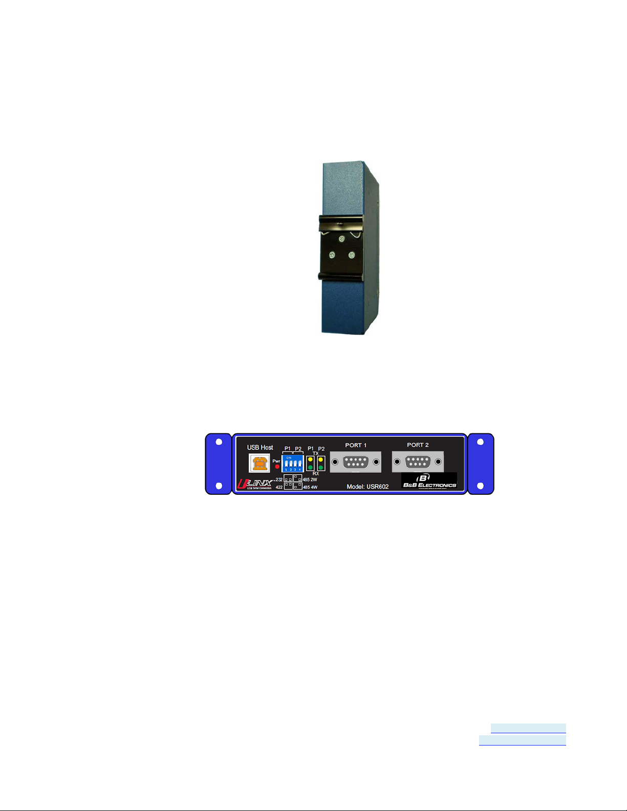
Installing and Mounting the USR60x
USR60x converters come supplied with DIN rail mounting clips and
panel mount adapters.
The DIN rail mounting clip is attached to the back of the unit using
three machine screws (included). This mount enables the unit to be
clipped directly to a standard DIN rail.
Panel mount adapters are attached to the unit with three machine
screws on each side. With this mount the unit can be installed in a
panel. (Refer to dimensional diagrams for the dimensions required for
predrilling the panel.
Connecting Power
Figure 6: DIN Rail Mounting Clip
Figure 7: USR602 with Panel Mount Adapters
USR60x converters of fer three options for connection of power:
• USB bus powered
Page 18 of 45 Document Number: USR60x-0812m
www.bb-elec.com/
www.bb-europe.com/
Page 19

Section 5 - Hardware Installation
• External power via pluggable terminal strip - 10 to 48 VDC, 16 watts
max
• External power via locking power jack - 10 to 48 VDC, 16 watts max
Figure 8: Power Supply Connections
When the unit is USB powered the current available to the converter
may be limited by the USB host. If the converter is connected to an
external USB hub the maximum available current may be insufficient to
operate the converter. In that case an external power supply should be
connected.
Connecting to a P C
USR60x converters connect to a host device (PC) via a USB interface.
The connector on the USR60x converter is a high retention force Type
B female connector.
Figure 9: USB Connector
Page 19 of 45 Document Number: USR60x-0812m
www.bb-elec.com/
www.bb-europe.com/
Page 20

Section 5 - Hardware Installation
3
Transmit Data (TD)
TDB(+)
DATA B(+)
6
Data Set Ready (DSR)
---
---
Connecting to the Serial Ports
The USR602 provides two serial ports; the USR604 has four. DB-9M
connectors are used for RS-232, RS-422 and RS-485 two-wire and
four-wire connections.
Figure 10: DB-9M Serial Port Connectors
The following illustration shows the pin numbering of the DB-9M
connector.
Figure 11: DB-9F Pin Numbering
The following table shows the wiring pin-outs for R S-232, RS-422 and
RS-485 two-wire and four-wire connections.
Pins RS-232 (DTE) RS-422/RS-485 (4-wire) RS-485 (2-wire)
1 Data Carrier Detect (DCD) RDA(-) --2 Receive Data (RD) RDB(+) ---
4 Data Terminal Ready (DTR) TDA(-) DATA A(-)
5 Signal Ground (GND) GND GND
7 Request To Send (RTS ) --- --8 Clear To Send (CTS) --- --9 Not Used --- ---
Page 20 of 45 Document Number: USR60x-0812m
www.bb-elec.com/
www.bb-europe.com/
Page 21

Section 5 - Hardware Installation
Termination and Biasin g
USR60x converters include intern al biasing resistors on the RS-422/RS485 interfaces.
The values for internal biasing resistors are:
Biasing: 1k ohms (default IN PLACE when in RS-422/485 modes)
The biasing resistors are connected to the receive lines, pulling the
RDA(-) line to ground and the RDB(+) line to a positive voltage. The
bias resistor is automatically IN when you select RS-422/485 mode.
For additional information on termination and biasing download the RS442 and RS-485 Applications eBook from www.bb-elec.com or contact
Technical Support at B&B Electronics: 815-433-5100
Setting COM Port Operatin g Modes
The operating modes of the converter are configured by the positions
of DIP switches accessible on the USR60x enclosure. The DIP switches
on the USR602 are located on the front panel of the converter.
• Switches 1 and 2 configure Port 1
• Switches 3 and 4 configure Port 2
Figure 122: DIP Switches
The DIP switches on the USR604 are located on the top of the
enclosure near the power connectors (when the unit is positioned
vertically).
• Switches 1 and 2 configure Port 1
• Switches 3 and 4 configure Port 2
Page 21 of 45 Document Number: USR60x-0812m
www.bb-elec.com/
www.bb-europe.com/
Page 22

Section 5 - Hardware Installation
• Switches 5 and 6 configure Port 3
• Switches 7 and 8 configure Port 4.
Figure 133: USR604 DIP Switch and Power Connectors
Operating modes are RS-232, RS-485 two-wire half-duplex, RS-485
four-wire full-duplex, and RS-422.
Port Switch RS-232 RS-422
1 Off (down) On (up) Off (down) On (up)
Port 1
2 Off (down) On (up) On (up) Off (down)
3 Off (down) On (up) Off (down) On (up)
Port 2
4 Off (down) On (up) On (up) Off (down)
5 Off (down) On (up) Off (down) On (up)
Port 3
6 Off (down) On (up) On (up) Off (down)
7 Off (down) On (up) Off (down) On (up)
Port 4
8 Off (down) On (up) On (up) Off (down)
RS-485
4-wire
RS-485
2-wire
Page 22 of 45 Document Number: USR60x-0812m
www.bb-elec.com/
www.bb-europe.com/
Page 23

Section 5 - Hardware Installation
Port 3 Rx
Blinking Green
Data being received on Port 3
Port 4 Tx
Blinking Yell ow
Data being transmitted on Port 4
LED Indicators
USR602 converters include five LED indicators; USR604 converters
include nine LED indicators. In both models one indicates the presence
of power; the others indicate transmit and receive data present on
each port.
Figure 144: USR602 LED Indicators
Figure 155: USR604 LED Indicators
LED Function Color Indicates
Power Green Presence of power
Port 1 Rx Blinking Green Data being received on Port 1
Port 1 Tx Blinking Yellow Data being transmitted on Port 1
Port 2 Rx Blinking Green Data being received on Port 2
Port 2 Tx Blinking Yellow Data being transmitted on Port 2
Port 3 Tx Blinking Yellow Data being transmitted on Port 3
Port 4 Rx Blinking Green Data being received on Port 4
Page 23 of 45 Document Number: USR60x-0812m
www.bb-elec.com/
www.bb-europe.com/
Page 24

Page 25

Section 6 - Advanced User Settings
......
.........................
..........................
SECTION 6
Advanced User Settings
In This Section
Setting Serial Port Properties ................................
Advanced Settings in Device Manager
Modbus Basics ................................
.
Serial port parameters and other advanced settings are conf igured on
the USB Isolated Serial Port Properties and Advanced Settings
windows, which are accessible via the Device Manager. The Device
Manager can be accessed through the Windows Control Panel.
Figure 166: Device Manager
Page 25 of 45 Document Number: USR60x-0812m
www.bb-elec.com/
www.bb-europe.com/
Page 26
Section 6 - Advanced User Settings
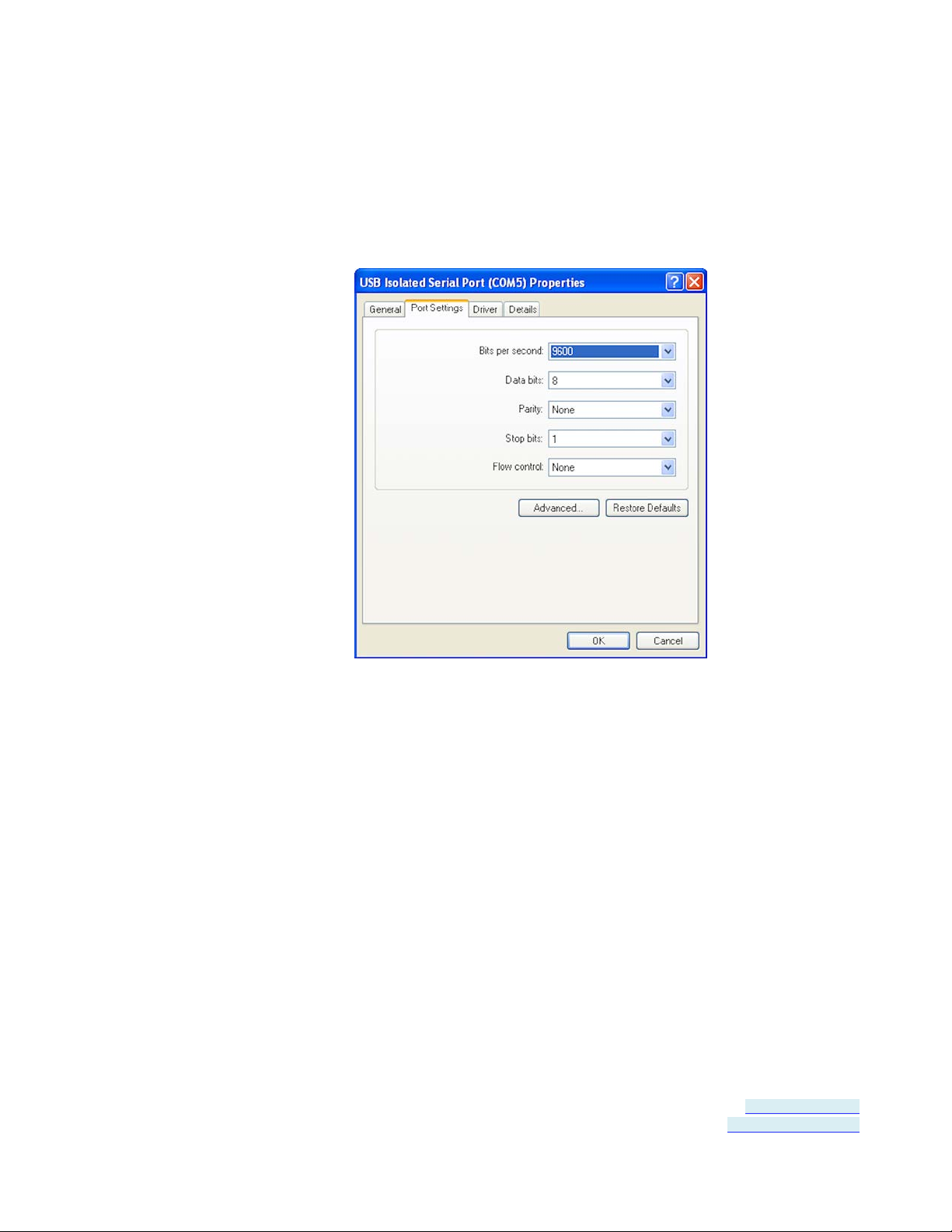
Setting Serial Port Propertie s
1. In Device Manager, expand Ports and double-click USB Isolated
Serial Port to open the USB Isolated Serial Port Properties dialog
box.
Figure 177: Port Properties
2. In the dropdown lists provided, select the following serial port
properties required for your communications application:
• Bits per second
• Data bits
• Parity
• Stop bits
• Flow control
Note: The default values for this dia log are 9600 bps, 8 data bits, No par ity, 1 stop bit, No flow
control
Page 26 of 45 Document Number: USR60x-0812m
www.bb-elec.com/
www.bb-europe.com/
Page 27
Section 6 - Advanced User Settings
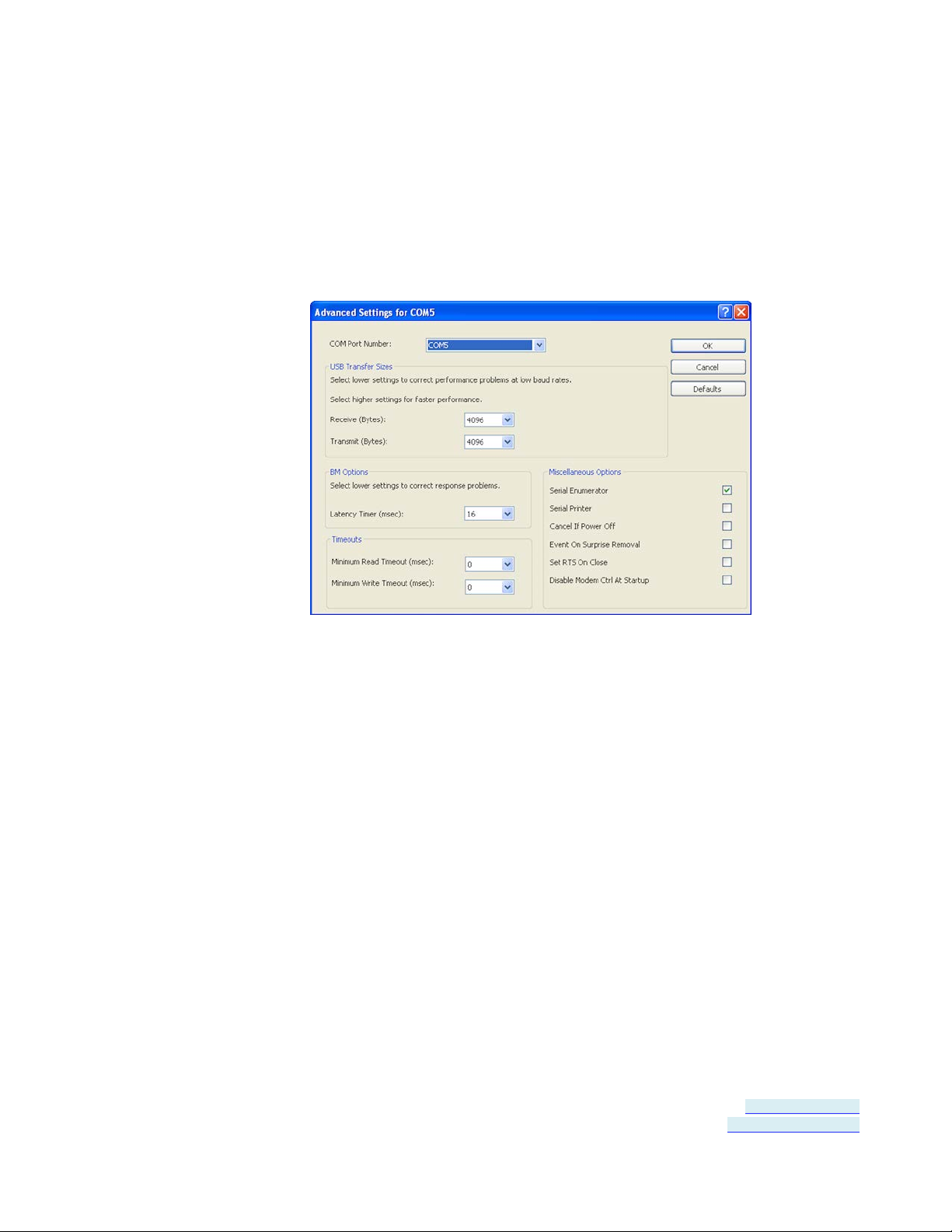
Advanced Settings in Device Manager
To configure advanced settings, on the USB Isolated Serial Port
Properties dialog, click Advanced...
The Advanced Settings dialog appears.
Configure the advanced settings as required (refer to the following
sections for details) and click OK to store the settings.
COM Port Number
When installing the drivers the first available COM port number is
assigned to the first COM port on the USR60x device.
If necessary the default communications port number can be changed
by selecting a new number in the COM Port Number dropdown list.
USB Transfer Sizes
Receive and transmit message sizes between 64 bytes and 4096 bytes
can be selected. The default value is 4096.
Figure 188: Advanced Settings
Page 27 of 45 Document Number: USR60x-0812m
www.bb-elec.com/
www.bb-europe.com/
Page 28

Section 6 - Advanced User Settings
Select lower settings to correct performance problems at low baud
rates. Select higher settings for faster performance.
BM Options
The BM Options dropdown list provides a setting for the Latenc y Timer.
The latency timer is a form of time-out mechanism that counts from
the last time data was sent from the USR60x back to the PC. If the
latency timer expires, the USR60x will send any data it has available to
the PC. It then resets and begins counting again.
Timer settings from 1 to 255 msecs are available. The default value is
16 msec.
Select lower settings to correct response problems.
Timeouts
The USB timeout is the maximum time in milliseconds that a USB
request can remain outstanding. Minimum read and write timeout
values between 0 and 10000 msec can be selected.
The default values are 0 for both read and write timeouts.
Miscellaneous Options
The following settings can be selected or deselected by clicking the
appropriate checkbox:
Serial Enumerator - The function of the serial enumerator is to detect
a Plug-and-Play enabled device (such as a serial mouse or serial
modem) that is attached to the USB serial port.
Serial Printer - If enabled, serial printer will d isable timeouts to allow
for long delays associated with paper loading.
Cancel If Power Off - The Cancel If Power Off option can be used to
assist with problems encountered when going into a hibernate or
suspend condition. This will cancel any requests re ceived by the driver
when going into hibernate or suspend.
Page 28 of 45 Document Number: USR60x-0812m
www.bb-elec.com/
www.bb-europe.com/
Page 29

Section 6 - Advanced User Settings
Event On Surprise Removal - The Event On Surprise Removal option
is generally left unselected.
Set RTS On Close - Selecting the Set RT S On Close option will set the
RTS signal on closing the port.
Disable Modem Ctrl At Startup - This option is used to control the
modem control signals DTR and RTS at startup. Devices that monitor
these signals can enter the wrong state after an unplug-replug cycle on
USB.
Page 29 of 45 Document Number: USR60x-0812m
www.bb-elec.com/
www.bb-europe.com/
Page 30

Section 6 - Advanced User Settings
Modbus Basics
Modbus is an industrial data communicatio ns protocol that emerged in
the mid-1970s and continues to be widely used in current industrial
systems. Originally designed to link terminals with Modicon PLCs, it is
simple, easy to learn and implement, and free to use. It quickly
became a defacto standard in the industry and has been widely
implemented with successful results.
Modbus is a message-based master/slave protocol (also sometimes
referred to as master/client) typically implemented across serial
communications links such as RS-232, RS-422 and RS-485. It supports
asynchronous point-to-point and multidrop communications.
The original Modbus specification included two possible transmission
modes: ASCII and RTU. Modbus RTU mode is the most common
implementation, using binary coding and CRC error-checking. Modbus
ASCII messages (though somewhat more readable because they use
ASCII characters) is less efficient and uses less effective LRC error
checking. ASCII mode uses ASCII characters to begin and end
messages whereas RTU uses time gaps (3.5 character times) of s ilence
for framing. The two modes are incompatible so a device configured for
ASCII mode cannot communicate with one using RTU.
Although some newer equipment using Modbus incorporates USB
interfaces, most legacy equipment implements RS-232, RS-422 and
RS-485. Most new PCs have eliminated RS-232 ports as standard
features and RS-422/485 was never a standard feature. As a result
USB to serial converters such as the USR60x are often necessary to
communicate between PCs and legacy systems that implement Modbus
protocol.
Page 30 of 45 Document Number: USR60x-0812m
www.bb-elec.com/
www.bb-europe.com/
Page 31

Section 7 - Specifications
................
.............................
........................
..................
..................
............
SECTION 7
Specifications
In This Section
Product Specification s ................................
Certifications ................................
Default Settings ................................
USR602 Dimensions ................................
USR604 Dimensions ................................
Panel Mount Dimensions ................................
.
Page 31 of 45 Document Number: USR60x-0812m
www.bb-elec.com/
www.bb-europe.com/
Page 32

Section 7 - Specifications
Category
x64, Windows V ista, Wind ows Vista x64, W indows Server 2003, Windows Server 2 003 x64,
Dimensions
USR602: 5.440in x 1.4in x 3. 5in (13.8cm x 3.54cm x 8.75cm)
Storage temperature
-40C to 85C
Humidity
5% to 90% non-condensing
LED indicat ors
Power - conti nuously on if powered via external supply or USB bus
Product Specificati ons
Specification
Models USR602, USR604
User documen tation User manual: on CD and B&B website
Data sheet: on B&B website
Quick Start Guide: Printed
Software Included on CD
Operating Systems Supported Server 2008 R2, Windows 7, Windows 7 x64, Windows Server 2008, Windows Ser ver 2008
Windows XP, Windows XP x64, Windows 20 00
USR604: 8.00in x 1.4in x 4. 70in (20.30c m x 3.54cm x 12.0cm)
Protocols USB 1.1 and 2.0
Speed 1.5Mbps, 12 Mbps, 480 Mbps
Isolation 2 kV port to port
Upstream connector Type B high retention (15 Newton / 3. 4 lbs withdrawal force)
Serial conn ector One DB-9M connector for each s erial port
Serial modes R-232 (DTE), RS-485 two-wire, RS-485 four-wire
RS-232 lines supported TD, RD, RTS, CTS, DTR, DSR, DCD, GND
RS-422/485 lines (4-wire) TDA(-), TDB(+), RDA(-), RDB(+), GND
RS-485 lines (2-wire) DATA A(-), DATA B(+), GND
RS-422/485 HS loopback Loop back RTS to CTS, DTR to DSR/DCD
Baud rate
Data bits 5, 6, 7, 8
Stop bit(s) 0, 1, 2
Switches Quad DIP switch f or user hardware selecti bility per port
Power supply requirement 10VDC to 48VDC
Power supply connectors Three position rem ovable terminal block, threaded barrel jack with center +
Operating temperature -40C to 80C
300, 600, 1200, 1800, 2400, 4800, 7200, 9600, 14400, 19200, 38400, 57600, 11 5200,
230400, 460800, 921600
(kbps)
Parity none, odd, even
Driver WHQL
Enclosure mounting DIN adapter, Panel mounting wi th mounting kit
Accessories Power supply: 12 VDC wall plug
Page 32 of 45 Document Number: USR60x-0812m
www.bb-elec.com/
www.bb-europe.com/
Four communication LEDs: P1 TX, P1 RX, P2 TX, P2 RX - gr ee n, blink wh en data p r esent
Cables: USB cable included with product
Mounting: DIN adapter inc luded on encl osure
Page 33

Section 7 - Specifications
Category
Specification
EN61000-4-3:2006 – (RI) 10V/m, 80 to 1000 MHz; 3 V/m, 1.3 to 2.7 GHz
Shock
IEC60068-2-27 – 50G peak, 11ms, 3 axis
Vibration
IEC60068-2-6 – 10 to 500 Hz, 4G, 3 axis
Freefall (drop)
IEC60068-2-32 – 10 total drops from sides, c orner and edges ; 1M
Certifications
Emissions FCC Class B, CI SPR Class B (EN55022)
CE EN61000-6-2:2005 – Heavy Industrial
EN61000-4-2:2008 – (ESD) ±8kV contact, ± 15kV air
EN61000-4-4:2004 – (EFT Burst) ±2kV DC ports; ±1kV signal ports
EN61000-4-5:2005 – (Surge) ±1kV Signal Ports
EN61000-4-6:2005 – (CI) 10 VRMS , 0.15 to 80 MHz
EN61000-4-8:2001 – (Magneti c) 10A/m, 50 Hz and 60 Hz
Information – FCC rules
This device complies with Part 15 of the FCC rules. Operation is subject to the following two conditions:
(1) This device may not cause harmful interference.
(2) This device must accept any interference that may cause undesired operation.
Information – UL Class 1 Div 2
Suitable for use in Class 1, Division 2, Groups A, B, C and D Hazardous Locations, or Nonhazardous locations
only.
WARNING - EXPLOSION HAZARD – DO NOT DISCONNECT EQUIPMENT WHILE THE CIRCUIT IS LIVE
UNLESS THE AREA IS KNOWN TO BE FREE OF IGNITABLE CONCENTRATIONS.
Install in accordance with control drawing number 9340R0.
Ind. Cont. Eq.
For HAZ LOC
3HTV
E245458
Class I, Div. 2, Groups A, B, C & D
Temp. Code: T4A
Page 33 of 45 Document Number: USR60x-0812m
www.bb-elec.com/
www.bb-europe.com/
Page 34

Section 7 - Specifications
Bits per second
9600
Data bits
8
Parity
None
Stop Bits
1
Flow Control
None
COM Port
first available over COM port 4
Category
Value
USB Transfer Size - Receive
USB Transfer Size - Transmit
Disable Modem Ctrl At St artup
Off
Default Settings
Basic Settings
Category Value
Serial Interface RS-232 (both DIP switches off)
Advanced Settings
4096 bytes (max)
4096 bytes (max)
Latency Timer 16
Minimum Read Tim e out 0
Minimum Write Timeout 0
Serial Enumerator On
Serial Print er Off
Cancel If Power Off Off
Event On Surprise Remo val Off
Set RTS On Close Off
Page 34 of 45 Document Number: USR60x-0812m
www.bb-elec.com/
www.bb-europe.com/
Page 35

Section 7 - Specifications
USR602 Dimensions
Figure 19: USR602 Dimensional Diagram
Page 35 of 45 Document Number: USR60x-0812m
www.bb-elec.com/
www.bb-europe.com/
Page 36

Section 7 - Specifications
USR604 Dimensions
Figure 20: USR604 Dimensional Diagram
Page 36 of 45 Document Number: USR60x-0812m
www.bb-elec.com/
www.bb-europe.com/
Page 37

Section 7 - Specifications
Panel Mount Dimensions
Figure 21: USR602 Panel Mount Dimensions
Figure 22: USR604 Panel Mount Dimensions
Page 37 of 45 Document Number: USR60x-0812m
www.bb-elec.com/
www.bb-europe.com/
Page 38

Page 39
Section 8 - Appendix
..........................
......................
SECTION 8
Appendix
In This Section
Loopback Test ................................
Serial Port Wiring ................................
Loopback Test
To verify the operation of the USB to serial converter perform a
loopback test using the following procedure:
1. Connect the converter to the PC with a USB cable and install the
driver using the procedure provided in the Software Installation (on
page 13) section of this manual.
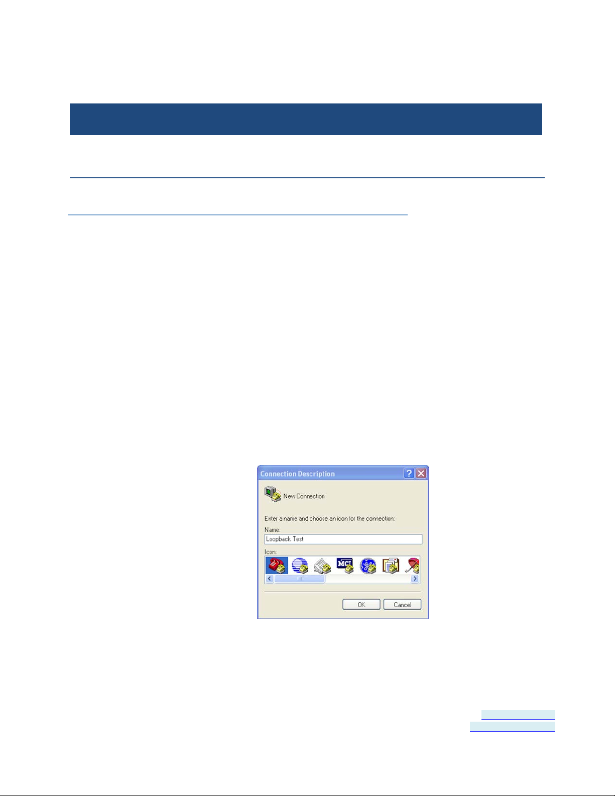
2. On the PC open HyperTerminal (found in the Program files under
Accessories / Communi ca tions).
Figure 23: Hyperterminal Connection Name
Page 39 of 45 Document Number: USR60x-0812m
www.bb-elec.com/
www.bb-europe.com/
Page 40

Section 8 - Appendix
3. Enter a connection name and click OK.
Figure 24: Selecting the COM Port
4. On the Connection using: dropdown list, select the port on the
converter to be tested.
5. Click OK.
Figure 25: Setting the Port Settings
6. On the Properties / Po rt Settings dialog, ensure Flow control is set
to None.
7. Click OK.
Page 40 of 45 Document Number: USR60x-0812m
www.bb-elec.com/
www.bb-europe.com/
Page 41
Section 8 - Appendix
8. Set the serial port to RS-232 mode by switching both associated DIP
switches to Off.
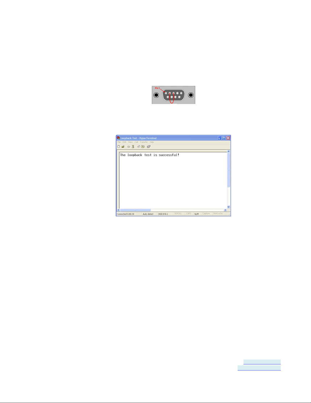
9. Plug a loopback plug into the DB9M connector associated with the
serial port to be tested.
10. Type some characters on the PC's keyboard.
The characters should appear on the HyperTerminal window.
Figure 26: Successful Hyperterminal Port Test
11. Remove the loopback plug and type more characters.
No additional characters should appear on the HyperTerminal
Page 41 of 45 Document Number: USR60x-0812m
www.bb-elec.com/
www.bb-europe.com/
window.
Page 42
Section 8 - Appendix
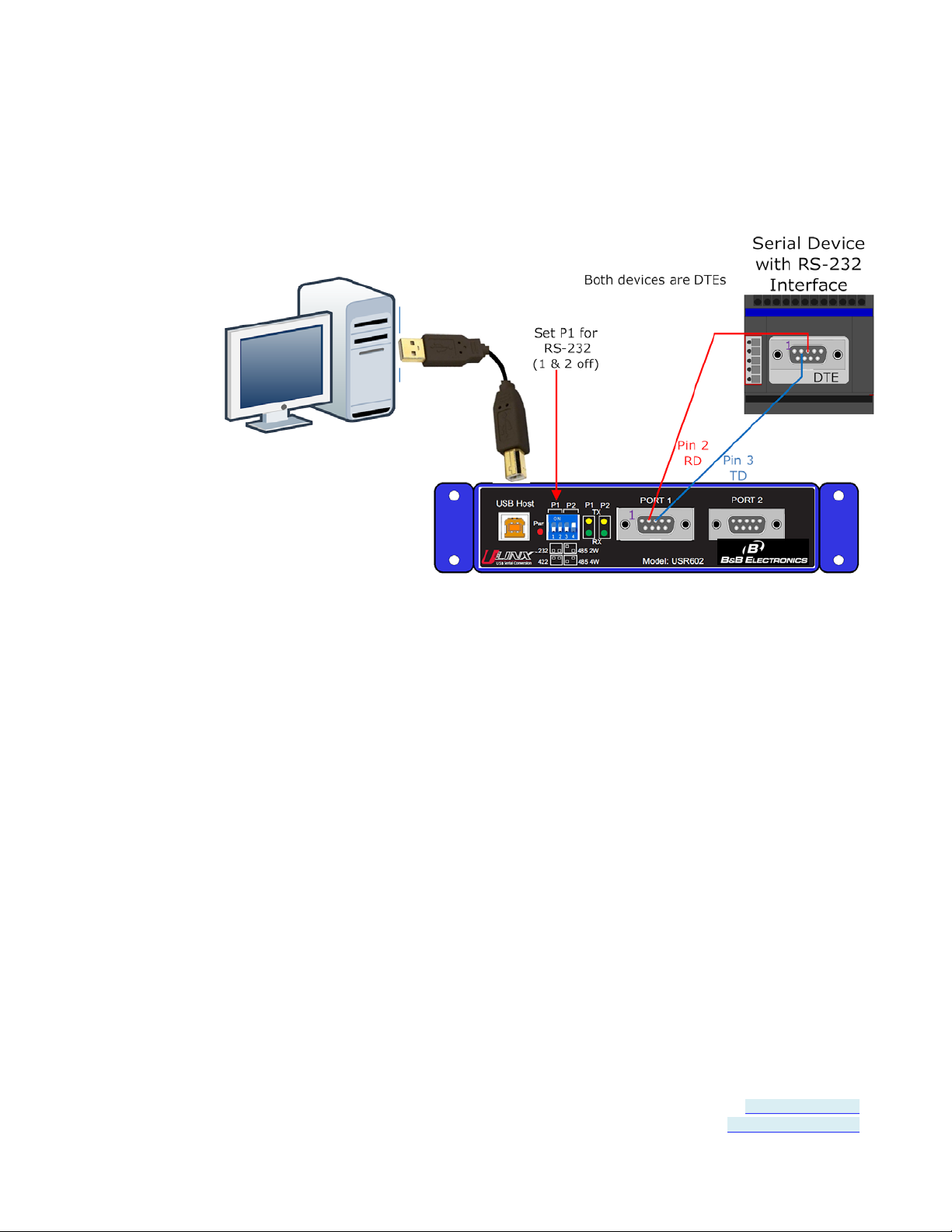
Serial Port Wiring
RS-232 Connections
Figure 27: USR602 RS-232 Connections
Page 42 of 45 Document Number: USR60x-0812m
www.bb-elec.com/
www.bb-europe.com/
Page 43
Section 8 - Appendix
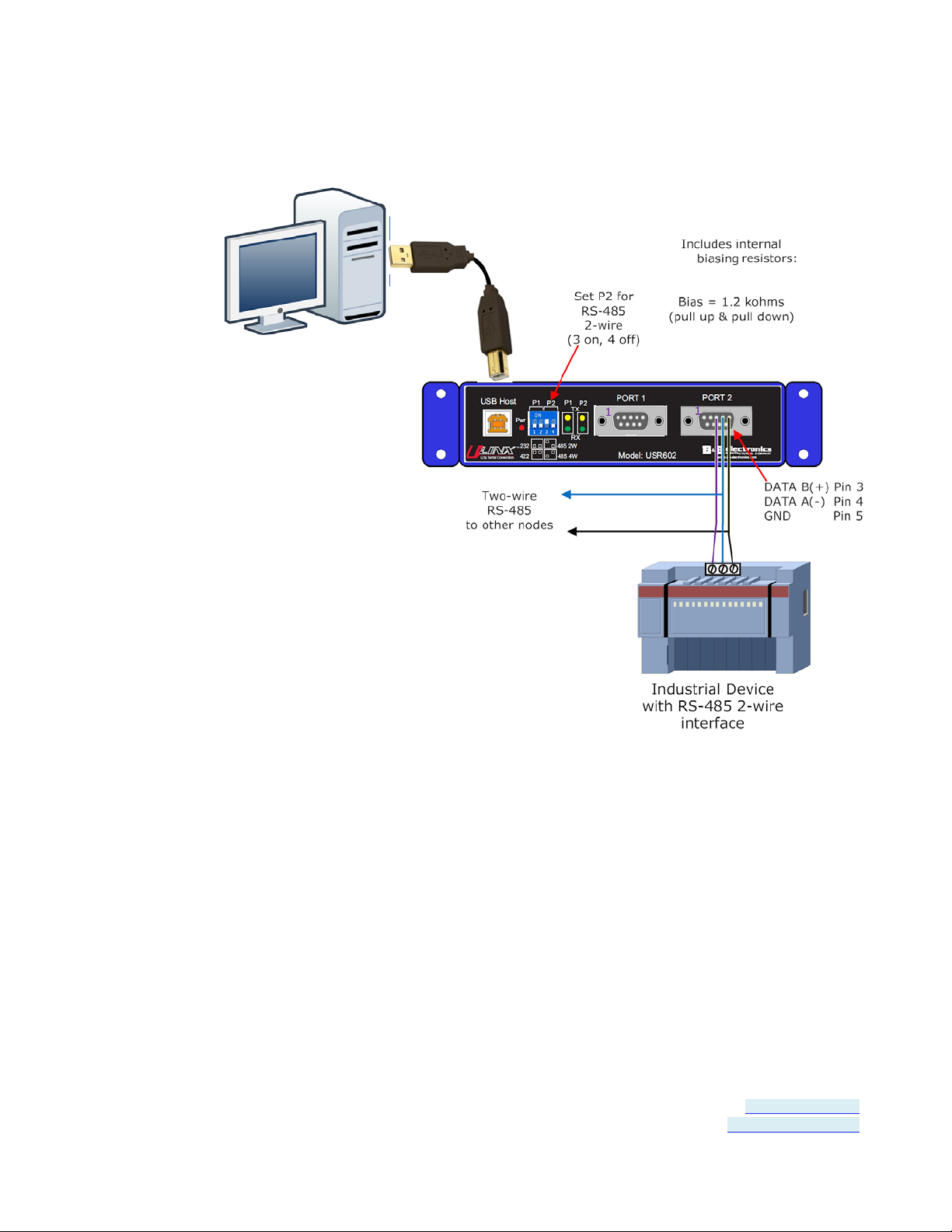
RS-485 Two-Wire Connections
Figure 28: USR602 RS-485 Two-Wire Connections
Page 43 of 45 Document Number: USR60x-0812m
www.bb-elec.com/
www.bb-europe.com/
Page 44

Section 8 - Appendix
RS-422 and RS-485 Four-Wire Connections
Figure 29: USR602 RS-422/485 Four-Wire Connections
Page 44 of 45 Document Number: USR60x-0812m
www.bb-elec.com/
www.bb-europe.com/
Page 45

Index
P
Package Contents • 5
A
About this Manual • 4
Advanced Settings in Device Manager • 8,
23
Advanced User Settings • 21
Appendix • 35
B
BM Options • 24
C
Certifications • 29
COM Port Number • 23
Connecting Power • 7, 14
Connecting to a PC • 15
Connecting to the Serial Ports • 8, 16
D
Panel Mount Dimensions • 33
Product Feature Summary • 4
Product Information • 5
Product Specifications • 27
Q
Quick Start Guide • 7
R
RS-232 Connections • 38
RS-422 and RS-485 Four-Wire
Connections • 8, 40
RS-485 Two-Wire Connections • 8, 39
S
Safety • 4
Serial Port Wiring • 38
Setting COM Port Operating Modes • 8, 18
Default Settings • 30
Hardware Installation • 13
Installing and Mounting the USR60x • 14
Installing the Driver • 7, 9
LED Indicators • 7, 20
Loopback Test • 8, 35
Miscellaneous Options • 24
Modbus Basics • 26
Overview • 3
Page 45 of 45
H
I
L
M
O
Setting Serial Port Properties • 22
Software Installation • 9, 35
Specifications • 27
T
Termination and Biasing • 17
Timeouts • 24
Typical Applications / Modes of Operation
• 6
U
Un-Installing the Driver • 11
USB Transfer Sizes • 23
USR602 Dimensions • 31
USR604 Dimensions • 32
USR60x Models • 5
 Loading...