

Page 1
Document Number 8940R003-USR60x-0812qsg
Quick Start Guide
4
Install the Driver Software
2
Mount the Converter
Connect Power
3
1
Check Included Items
1. Unpack the USB to serial converter from the shipping
container. Verify that all included items are present.
• 2 or 4 port industrial USB to serial converter
• Two meter USB cable
• Panel mount adapters
• DIN rail mount adapter
• Driver CD
• This quick start guide
Industrial 2 & 4 Port USB to Serial
Converters
Models USR602 & USR604
3. Mount the product using the included DIN clip or
included Panel Mount adapter kit.
10. Using the included USB cable, connect one end of
the cable to the Host PC. Plug the other end of the
cable into the USR60x device via the port marked
USB Host. If this is the first installation on this
computer, the COM ports will be assigned (Step
2.d.).
Panel Mounting
7. To install locate the included panel mount kit which
includes two bracket pieces and 4 installation
screws (2 screws per bracket).
Note: The Panel Mount Brackets can be mounted
to either side of the USR60x device and allows
mounting Up, Down, Forward and Back.
8. Using the 4 screws (2 per bracket) attach the
brackets to the device. The shorter side of the
bracket in which the holes are close together is the
side that will mount to the device. The bracket when
installed correctly will form an L shape with the side
of the enclosure.
9. Once the brackets are installed the product is ready
to be mounted.
DIN Rail Mounting
4. To install locate the included DIN rail
mount kit which includes the bracket and
3 installation screws.
Note: The DIN rail mounting bracket
can only be installed on the back side
of the converter.
5. Find the 3 mounting holes located on the
back side of the hub and install the
mounting bracket with the flat surface
facing the back of the hub with the
included mounting screws.
6. The product is now ready to be mounted
on a piece of DIN rail.
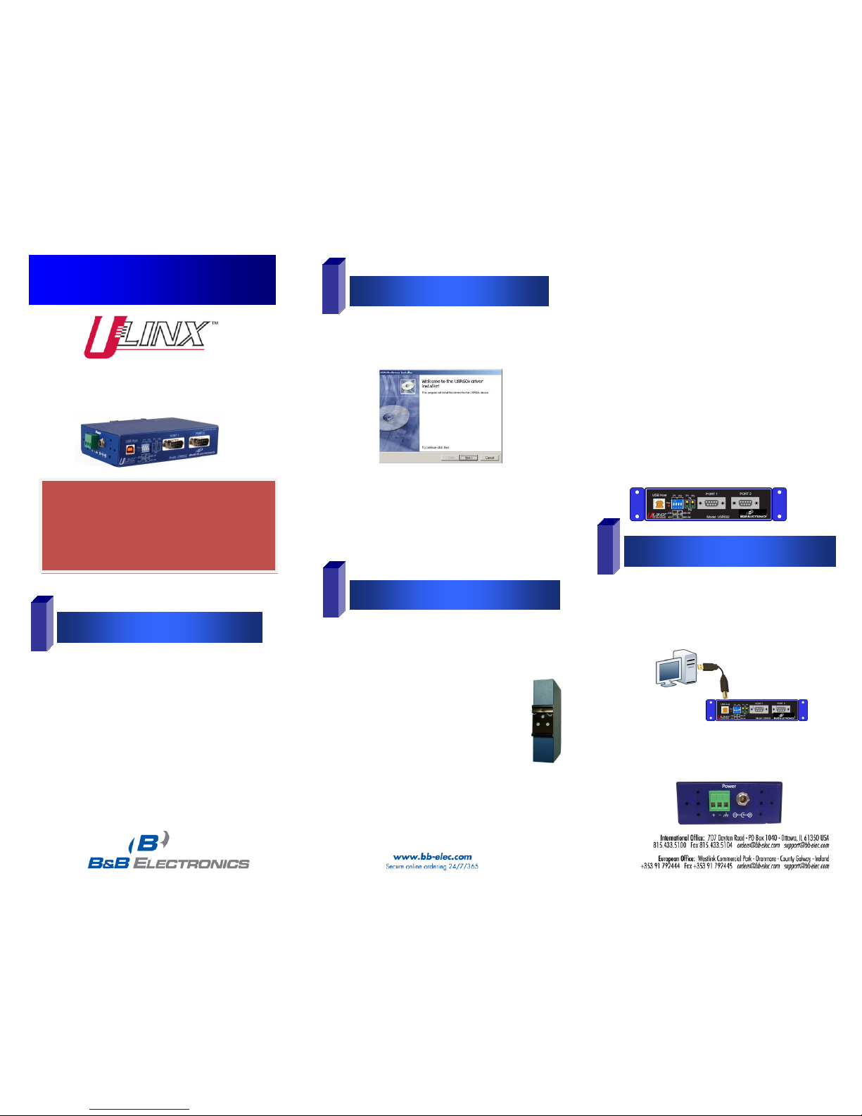
2. The driver software in contained on the CD that is
packaged with your converter.
a. Put the driver CD into the PC. The setup
program should automatically launch.
b. Click Next. Accept the license agreement
and click Next again.
c. The program will install the drivers and
screen will be displayed indicating
successful installation
d. When you connect the converter to your
PC for the first time, each COM port will
be configured. This could take up to 30
seconds for each COM port.
11. For the USR604, add 10 to 48 VDC power via the
terminal block or barrel jack. (For redundancy power
can be applied to both.)
DRIVER SOFTWARE SHOULD BE
INSTALLED BEFORE THE CONVERTER IS
CONNECTED TO YOUR USB PORT.
PLEASE READ THESE INSTRUCTIONS
BEFORE PROCEEDING.
Page 2
Document Number 8940R003-USR60x-0812qsg
Check LED Indicators
5
Set Up COM Port Modes
Connect Serial Ports
Configure Serial Ports
Model USR604
Model USR602
Perform a Loop back Test
LED Type
Indication when ON
Pwr
Product is receiving adequate voltage and
current from USB or local power source
Tx Serial interface is transmitting data
Rx Serial interface is receiving data
DIP
Switch
RS-232 RS-422
RS-485
4-wire
RS-485
2-wire
Port
1
1 Off On Off On
2 Off On On Off
Port
2
3 Off On Off On
4 Off On On Off
Port
3
5 Off On Off On
6 Off On On Off
Port
4
7 Off On Off On
8 Off On On Off
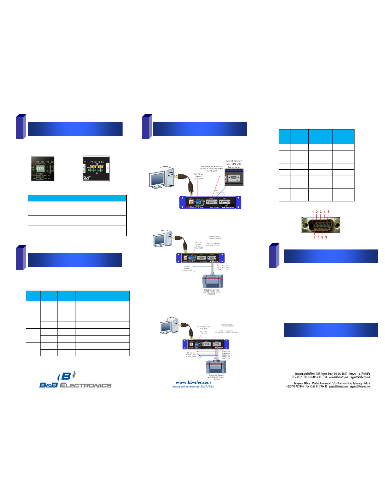
14. USR60x in RS-232 mode is a DTE. To connect to
another RS-232 DTE device, use a null (crossover)
cable.
15. Connect to an RS-485 2-wire network as shown
below:
16. Connect to an RS-422 device or an RS-485 4-wire
network as shown below:
18. On the PC screen, open the Control Panel.
19. Click System to open the Device Manager
20. Under Ports, double-click the port to be configured.
21. On the Serial Port Properties window, set the
required communications parameters of system
with which you are communicating.
22. If necessary, click Advanced and set up the
Advanced Properties (refer to manual for
information)
6
7
8
12. Verify that the PWR LED indicates the presence of
power.
13. For each serial port, configure the DIP switches for
the desired serial interface:
17. Perform a loopback test to verify that the converter
is working (refer to the User Manual for details on
loopback testing).
Pins RS-232
(DTE)
RS-422/485
(4-wire)
RS-485
(2-wire)
1 DCD RDA(-) --2 RD RDB(+) --3 TD TDB(+) DATA B(+)
4 DTR TDA(-) DATA A(-)
5 GND GND GND
6 DSR --- --7 RTS --- --8 CTS --- --9 --- --- ---
 Loading...