

Page 1
P#8505R002_ULINX 2&4 PORT_0712qsg
Quick Start Guide
Ulinx USB to Serial Converters
2 Port and 4 Port Devices
1
Items Included
2
General
3
Installation
4
Verifying Installation
1. One USB port is required for each installed device.
The USB port can be native to the PC or it can be a
USB port from an installed USB hub to the PC.
2. Sleep & Hibernate: Windows 7 disables USB
transmit wile in Sleep & Hibernate.
Note: The device works with USB 1.1 or 2.0 ports but
has a maximum USB data rate of 12Mbps.
1. To verify the installation went correctly open the Windows
Device Manager
Scroll down to Ports,
Expand the ports by clicking on the plus sign (+), this
shows if the ports now exist on the PC.
If there are no exclamation points or other indicators of
a problem the ports should be installed correctly and
ready for use.
2. Verifying with a loopback test.
If the device is RS-232 loopback pins 2 and 3. If the
device is RS-422 or RS-485 (4-Wire) loopback the
TDA(-) to RDA(-) and TDB(+) to RDB(+), if desired use
the pin-out charts for the location of each pin or
terminal.
Using Hyper Terminal or similar program, connect to
the appropriate COM port. Set the desired baud rate.
Ensure Hyper Terminal local echo is OFF. (Note:
Hyper Terminal is not provided with Vista and 2003
Server)
Transmit data. If the same character string is returned,
the test is good.
USB to Serial Device
Two Meter USB Cable
CD ROM with Drivers
This Quick Start Guide
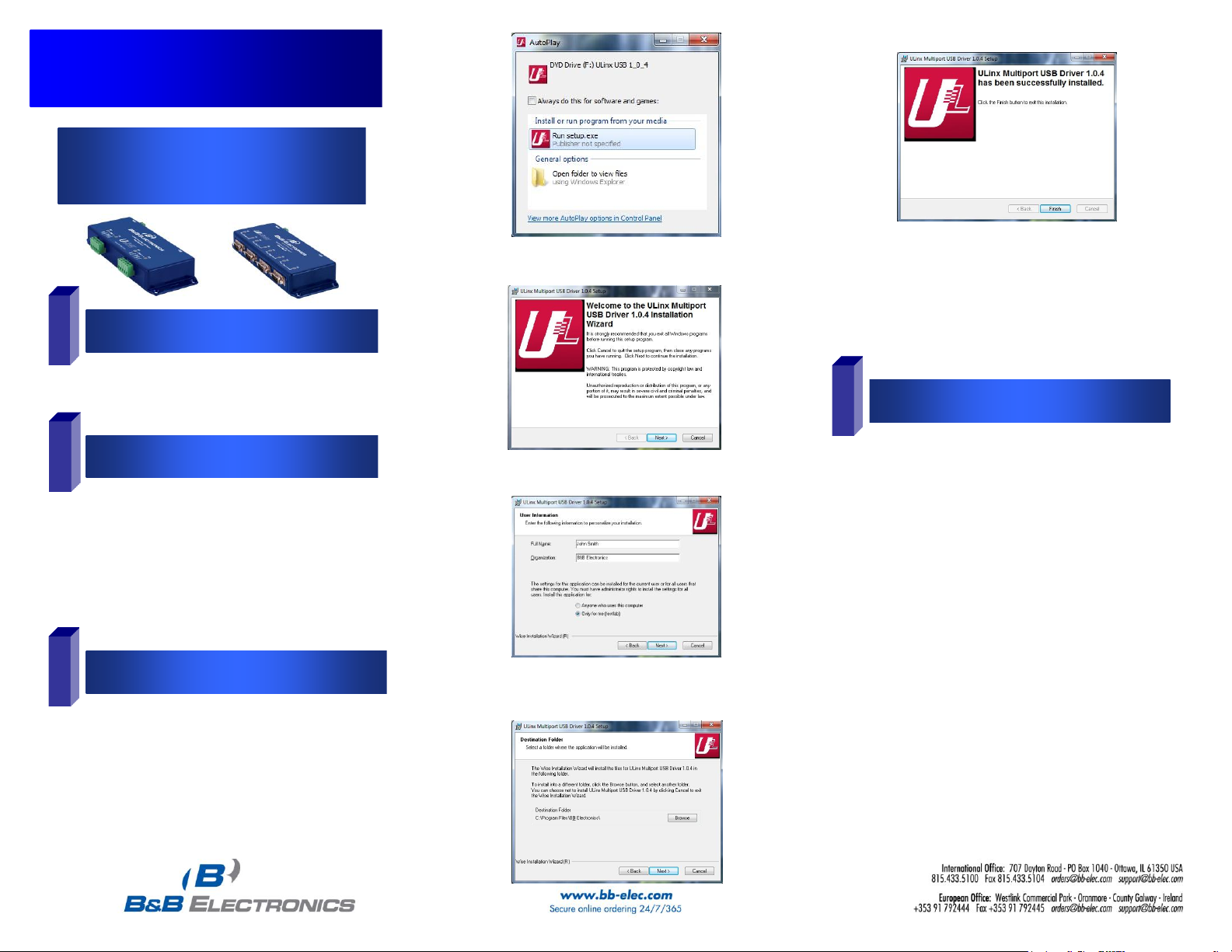
The CD contains a driver installation program. Install the
drivers using this program before connecting the USB
Converter to your computer.
The sample screen shots are from Windows 7.
Insert the included driver CD into the PC’s CD ROM bay
The Driver Install Program will start.
Select “Run setup.exe.”
Click “Next”
Fill in user information and click “Next.” Fill in destination drive
or use the default and click “Next.”
Installation is complete. Plug in your USB to Serial Converter. It
may take up to 30 seconds for each COM port to be assigned.
You can watch the progress in Device Manager.
Page 2
5
Dip Switch Setting
TDA(-)
TDB(-)
RDA(-)
RDB(-)
GND
USB
TO PC
RS-485
External Power Option:
USO9ML2-2P
10 to 30 VDC @ 3.0 W max.
USO9ML2-4P
10 to 30 VDC @ 5.0 W max.
USOPTL4-2P
10 to 30 VDC @ 3.0 W max.
USOPTL4-4P
10 to 30 VDC @ 5.0 W max.
Surrounding Air Ambient Temperature: 0 to 70° C
Dip Switch Settings
Switch Off (left) On (right)
1 RS-422 RS-485
2 ECHO ON ECHO OFF
3 4-Wire 2-Wire
4 4-WIre 2-Wire
6
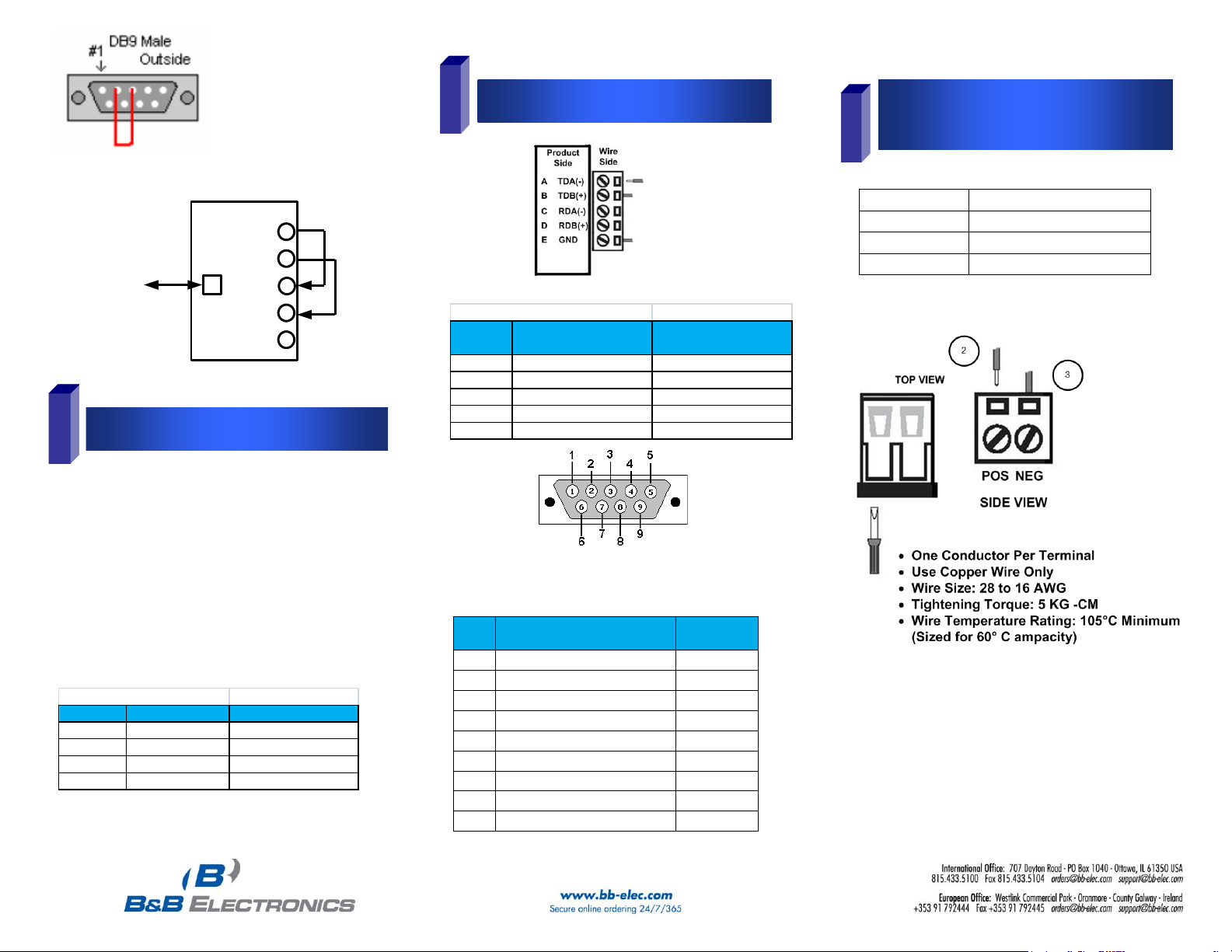
Pinouts
RS485 Pinout (Terminal Blocks)
Terminal
Position
RS-485, 4 Wire RS-485, 2 Wire
A Transmit TDA (-) Output Data A (-) Input / Output
B Transmit TDB (+) Output Data B (+) Input / Output
C Receive RDA (-) Input Data A (-) Input / Output
D Recieve RDB (+) Input Data B (+) Input / Output
E Ground Ground
Note: For models with selectable RS-422/485 configurations
Dip switches allow the module to be configured for two-wire or
four-wire, RS-422 or RS-485 modes. In two-wire mode the TDA (-)
and RDA (-) are tied together and so are TDB (+) and RDB (+),
making multi-dropping this converter into an existing network easy.
7
Optional External Power for
Optically Isolated Units
1. Loosen the screw to open the terminal block lead clamp.
2. Insert the power lead. TB will accept 28-16 AWG wire.
3. Tighten the screw to close the terminal block lead clamp. Ensure
the clamp holds the lead securely. However, do not over tighten.
NOTE: For Replacement Terminal Block, Order Part #7444.
NOTE: To remove drivers from a PC, there is an Uninstall
reference document on the CD ROM.
RS-232
RS-232 Pinout (DB9 Male DTE)
PIN
Signal Name
RS-232
Signals
1
DCD (Data Carrier Detect)
Input
2
RD (Receive Data)
Input
3
TD (Transmit Data)
Output
4
DTR (DTE Ready)
Output
5
SG (Signal Ground)
Ground
6
DSR (DCE Ready)
Input
7
RTS (Request to Send
Output
8
CTS (Clear to Send)
Input
9
RI (Ring Indicator)
Input
P#8505R002_ULINX 2&4 PORT_0712qsg
 Loading...