

Page 1

SPP-100
Enhanced Parallel Port
Type II PCMCIA Card
for PCMCIA Card Standard compatible machines
User's Manual
INTERFACE CARDS FOR IBM PC/AT AND PS/2
QUATECH, INC. TEL: (330) 655-9000
5675 Hudson Industrial Parkway FAX: (330) 655-9010
Hudson, Ohio 44236 http:\\www.quatech.com
Page 2

Page 3

Warranty Information
Quatech Inc. warrants the SPP-100 to be free of defects for one (1) year from
the date of purchase. Quatech Inc. will repair or replace any adapter that fails to
perform under normal operating conditions and in accordance with the procedures
outlined in this document during the warranty period. Any damage that results from
improper installation, operation, or general misuse voids all warranty rights.
The authors have taken due care in the preparation of this document and any
associated software program(s). In no event will Quatech Inc. be liable for damages of
any kind, incidental or consequential, in regard to or arising out of the performance or
form of the materials presented herein and in the program(s) accompanying this
document. No representation is made regarding the suitability of this product for any
particular purpose.
Quatech Inc. reserves the right to edit or append to this document or the
product(s) to which it refers at any time and without notice.
Please complete the following information and retain for your records. Have this
information available when requesting warranty service.
Date of purchase:
Model Number: SPP-100
Product Description: Type II PCMCIA Enhanced Parallel Port
Serial Number:
SPP-100 User's Manual i
Page 4

Declaration of Conformity
Manufacturer's Name: Quatech Inc.
Manufacturer's Address: 5675 Hudson Industrial Pkwy.
Hudson, OH 44236 (USA)
Application of Council Directive: 89/336/EEC
Standards to which
Conformity is Declared: * EN50081-1
(EN55022)
* EN50082-1
(IEC 801-2, IEC 801-3, & IEC 801-4)
Type of Equipment: Information Technology Equipment
Equipment Class: Commercial, Residential, & Light
Industrial
Product Name: PCMCIA Card
Model Number : SPP-100
ii Quatech Inc.
Page 5

Table of Contents
1 . Introduction
................................... .......
2 . DOS / Windows 3.x Installation
3 . Windows 95/98/ME Installation
4 . Windows NT Installation
...................... .......
5 . Windows 2000/XP Installation
6 . Windows CE Installation
....................... .......
................ .......
................ .......
.................. .......
1-1
2-1
2-22.1 SPP-100 Client Driver for DOS .................... .......
2-32.1.1 Client Driver Installation .................... .......
2-42.1.2 Command Line Options ..................... .......
2-72.1.3 Common Problems ......................... .......
2-82.2 SPP-100 Enabler for DOS ........................ .......
2-92.2.1 Command Line Options ..................... .......
2-122.2.2 Common Problems ......................... ......
3-1
3-13.1 Installing an SPP-100 in Windows 95/98/ME ....... .......
3-33.2 SPP-100 Resource Settings in Windows 95/98/ME ... .......
3-73.3 Common Problems ............................. .......
4-1
5-1
5-15.1 Installing an SPP-100 in Windows 2000/XP ......... .......
5-35.2 SPP-100 Resource Settings in Windows 2000/XP ..... .......
5-75.3 Common Problems ............................. .......
6-1
6-16.1 Installing an SPP-100 in Windows CE .............. .......
7 . OS/2 Installation
8 . Programming the SPP-100
9 . External Connections
............................... .......
...................... .......
.......................... .......
Appendix A: Parallel Port Terminology
........... ......
7-1
7-17.1 Installation of the OS/2 SPP-100 Client Driver ....... .......
7-27.2 Configurations ................................. .......
7-27.2.1 Configuration Notes ........................ .......
7-37.3 Interrupts for the SPP-100 Under OS/2 ............. .......
7-37.4 EPP Mode Under OS/2 .......................... .......
7-37.5 Monitoring The Status Of PCMCIA Cards .......... .......
8-1
8-18.1 Program Registers .............................. .......
8-28.2 Program Register description ..................... .......
8-28.2.1 Data Register ............................. .......
8-38.2.2 Device Status Register ...................... .......
8-48.2.3 Device Control Register ..................... .......
8-48.2.4 EPP Address Register ...................... .......
8-58.2.5 EPP Data Registers 0-3 ..................... .......
8-58.2.6 Extended Control Register .................. .......
9-1
A-1
SPP-100 User's Manual iii
Page 6

List of Figures
A-1A.1 Explanation of parallel port terminology ........... .......
1-1Figure 1. SPP-100 System Configuration. ..................... ..
2-1Figure 2. Client Driver versus Enabler for DOS/Windows 3.x. ... ..
3-1Figure 3. SPP-100 Driver Installation in Windows 95/98/ME .... ..
3-3Figure 4. Windows 95/98/ME Device Manager ................ ..
3-4Figure 5. SPP-100 Resource Allocations in Windows 95/98/ME .. ..
3-4Figure 6a. Windows 95/98/ME Basic Configurations Table (Rev. E) ..
3-5Figure 6b. Windows 95/98/ME Basic Configurations Table (Rev. E2) ..
3-6Figure 7. Windows 95/98/ME Edit Resources Window ......... ..
4-1Figure 8. Windows NT Explorer ............................ ..
4-2Figure 9. Windows NT Device Manager Icon on Desktop ........ ..
5-1Figure 10. SPP-100 Driver Installation in Windows 2000/XP ..... ..
5-3Figure 11. Windows 2000/XP Device Manager ................ ..
5-4Figure 12. SPP-100 Resource Allocations in Windows 2000/XP ... ..
5-4Figure 13a. Windows 2000 Basic Configurations Table (Rev. E) ..... ..
5-5Figure 13b. Windows 2000 Basic Configurations Table (Rev. E2) .... ..
5-5Figure 13c. Windows XP Basic Configurations Table (Rev. E2) ...... ..
5-6Figure 14. Windows 2000/XP Edit Resources Window .......... ..
8-1Figure 15. SPP-100 Program Registers Table ................... ..
8-2Figure 16. Data Register Table .............................. ..
8-3Figure 17. Device Status Register Table ....................... ..
8-4Figure 18. Data Control Register Table ....................... ..
8-5Figure 19. Extended Control Register Table ................... ..
8-5Figure 20. Parallel Port Modes Table ......................... ..
9-1Figure 15. Connector Signal Assignment ...................... ..
iv Quatech Inc.
Page 7
1. Introduction
The SPP-100 is an Enhanced Parallel Port (EPP) adapter for systems
equipped with PCMCIA Type II and/or Type III expansion sockets. The
SPP-100 is a PCMCIA Type II (5 mm) card and is PCMCIA PC Card
Standard Specification 2.1 compliant.
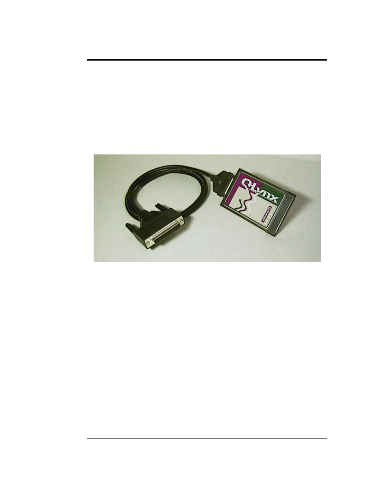
The figure below illustrates a complete SPP-100 system. The system
includes the CP-SPP cable assembly which converts the SPP-100’s 0.8mm
I/O connector into a standard D-25 female connector.
Figure 1. SPP-100 System Configuration.
Starting with the original PC, IBM defined the standard parallel printer
port. The original standard parallel printer port only supported data
output. The IBM PS/2 series added bi-directional support to the parallel
port. This was done by using one more bit in the control out register to
control tristating of the data out port. The next generation of parallel
ports is the EPP parallel port, which is defined by the IEEE P1284
standard. The IEEE standard defines a signaling method for
asynchronous, fully interlocked, bi-directional parallel communications
between hosts and printers or other peripheral devices.
The SPP-100 provides a single IEEE P1284 compliant EPP parallel port
which is also backward compatible with the standard PC-compatible
parallel port and the PS/2 type bi-directional parallel port.
SPP-100 User's Manual 1-1
Page 8

(This page intentionally left blank.)
1-2 Quatech Inc.
Page 9

2. DOS / Windows 3.x Installation
Two configuration software programs are provided with the SPP-100: a
Client Driver, SPP100CL.SYS, and a card Enabler, SPP100EN.EXE. Both
of these programs are executed from DOS (before entering Windows) and
allow operation of the SPP-100 in both the DOS and Windows 3.x
environments. For optimal operation, however, the Client Driver is the
preferred method of installation and configuration. The table below
highlights the differences between these programs.
Enabler (not recommended)Client Driver (recommended)
File name: SPP100EN.EXEFile name: SPP100CL.SYS
Interfaces to PCMCIA Card and
Socket Services software (PCMCIA
host adapter independent)
Allows automatic configuration of
SPP-100 adapters upon insertion
(Hot Swapping)
Requires PCMCIA Card and Socket
Services software
Interfaces directly to Intel 82365SL
and other PCIC compatible PCMCIA
host adapters
Does not support automatic
configuration of SPP-100 adapters
upon insertion (Hot Swapping)
Does not require PCMCIA Card and
Socket Services software
Figure 2. Client Driver versus Enabler for DOS/Windows 3.x.
Card and Socket Services software is commercially available from several
vendors for most desktop and laptop PCs. If you are unsure whether
Card and Socket Services software is currently installed on your system,
install the SPP-100 Client Driver as discussed in following section. When
loaded, the Client Driver will display an error message if Card and Socket
Services software is not detected.
SPP-100 User's Manual 2-1
Page 10

2.1 SPP-100 Client Driver for DOS
In order to use the SPP-100 Client Driver, the system must be configured
with Card and Socket Services software. Card and Socket Services
software is not provided with the SPP-100 but is available from Quatech.
IMPORTANT:
Some versions of Card and Socket Services dated before
1993 do not support general purpose I/O cards. If after
careful installation of the Client Driver the SPP-100 does
not configure or operate properly, an updated version of
Card and Socket Services may be required.
2-2 Quatech Inc.
Page 11

2.1.1 Client Driver Installation
The following procedure is used to install the SPP-100 Client Driver:
1. Copy the file SPP100CL.SYS from the SPP-100 distribution
diskette onto the system's hard drive.
2. Using an ASCII text editor, open the system's CONFIG.SYS file
located in the root directory of the boot drive.
3. Locate the line(s) in the CONFIG.SYS file where the Card and
Socket Services software is installed.
4. AFTER the line(s) installing the Card and Socket Services
software, add the following line to the CONFIG.SYS file:
DEVICE = drive:\path\SPP100CL.SYS options
where options are the SPP-100 Client Driver command line
options discussed on the following pages.
5. Save the CONFIG.SYS file and exit the text editor.
6. Insert the SPP-100 into one of the system's PCMCIA slots.
NOTE: Since the SPP-100 Client Driver supports "Hot Swapping",
it is not necessary to have the SPP-100 installed when booting the
system. By inserting the card before booting, however, the Client
Driver will report the adapter configuration during the boot
process thereby verifying the changes made to the CONFIG.SYS.
7. Reboot the system and note the message displayed when the
SPP-100 Client Driver is loaded. If the Client Driver reports an
"invalid command line option", correct the entry in the
CONFIG.SYS file and reboot the system again. If the Client
Driver reports "Card and Socket Services not found", a version
of Card and Socket Services must be installed on the system or
the SPP-100 Enabler program must be used to configure the
adapter. If the Client Driver reports the desired adapter
configuration, the installation process is complete and the
SPP-100 may be removed and / or inserted from the system as
desired. On each insertion into the PCMCIA socket, the
SPP-100 will be automatically reconfigured according to the
command line options.
SPP-100 User's Manual 2-3
Page 12

2.1.2 Command Line Options
The SPP-100 Client Driver accepts up to eight command line arguments
from the user to determine the configuration of the SPP-100. If any
arguments are provided, the Client Driver will attempt to configure any
SPP-100s with the options specified in the order they are entered on the
command line. Each argument must be enclosed in parenthesis and must
be separated from other arguments by a space on the command line.
Within each argument, any or all of the following parameters may be
specified using a comma (no spaces) to separate each parameter:
Baddress specifies the base I/O address of the SPP-100 in hexadecimal.
This address must reside on an even 8-byte boundary. If this
option is omitted, a base address will be assigned by Card and
Socket Services.
Iirq specifies the interrupt level (IRQ) of the SPP-100 in decimal.
irq must be one of the following values: 3, 4, 5, 7, 9, 10, 11, 12,
14, 15, or 0 if no IRQ is desired. If this option is omitted, an
interrupt level will be assigned by Card and Socket Services.
Ssocket specifies which PCMCIA socket the SPP-100 must be inserted
into for this configuration argument to be used. socket must be
in the range 0 - 15. If this option is omitted, the configuration
argument will apply to SPP-100s inserted into any socket.
Emode specifies EPP mode operation for the SPP-100 (This overrides
the mode selection bit in the Extended Control Register.). If
this option is omitted, the SPP-100 defaults to standard printer
port mode operation.
Llist specifies that the client driver update the BIOS equipment list
on card insertion and removal. If this option is omitted, the
BIOS equipment list is not updated.
2.1.2.1 Example 1
DEVICE = C:\SPP-100\SPP100CL.SYS
In example 1, no command line arguments are specified. The Client
Driver will configure an SPP-100 inserted into any socket with a base
address and IRQ assigned by Card and Socket Services. The SPP-100 will
2-4 Quatech Inc.
Page 13

operate as a standard printer port, and the BIOS equipment list will not be
updated.
2.1.2.2 Example 2
DEVICE = C:\SPP-100\SPP100CL.SYS (b278)
In example 2, a single command line argument is provided. The Client
Driver will attempt to configure an SPP-100 inserted into any socket at
base address 278H with an IRQ assigned by Card and Socket Services. If
address 278H is unavailable, the SPP-100 will not be configured. If
successfully configured, the SPP-100 will operate as a standard printer
port and the BIOS equipment list will not be updated.
2.1.2.3 Example 3
DEVICE = C:\SPP-100\SPP100CL.SYS (s0,b378,i7)
In example 3, a single command line argument is provided. The Client
Driver will attempt to configure an SPP-100 inserted into socket 0 with a
base address of 378H and IRQ 7. If address 378H or IRQ 7 is unavailable,
the SPP-100 will not be configured. In addition, if an SPP-100 is inserted
into any other socket, it will not be configured. If successfully configured,
the SPP-100 will operate as a standard printer port and the BIOS
equipment list will not be updated.
2.1.2.4 Example 4
DEVICE = C:\SPP-100\SPP100CL.SYS (i5,e,l,b220)
In example 4, a single command line argument is provided. Because the
parameter order is not significant, the Client Driver will attempt to
configure an SPP-100 inserted into any socket with a base address of 220H
and IRQ 5. If address 220H or IRQ 5 is unavailable, the SPP-100 will not
be configured. If successfully configured, the SPP-100 will operate in EPP
compatible printer port mode and the BIOS equipment list will be
updated by the client driver during card insertion and removal events.
2.1.2.5 Example 5
DEVICE = C:\SPP-100\SPP100CL.SYS (b3BC,i5) (i10) ( )
SPP-100 User's Manual 2-5
Page 14

In example 5, three command line arguments are provided. The Client
Driver will first attempt to configure an SPP-100 inserted into any socket
with a base address of 3BCH and IRQ 5. If address 3BCH or IRQ 5 is
unavailable, the Client Driver will proceed to the second command line
argument and attempt to configure the card with a base address assigned
by Card and Socket Services and IRQ 10. If IRQ 10 is also unavailable, the
Client Driver will proceed to the third command line argument and
configure the SPP-100 with a base address and an IRQ assigned by Card
and Socket Services. If successfully configured, the SPP-100 will operate
as a standard printer port and the BIOS equipment list will not be
updated.
2.1.2.6 Example 6
DEVICE = C:\SPP-100\SPP100CL.SYS (b3BC,i5) ( ) (i10)
In example 6, the three command line arguments of example 5 have been
rearranged. The Client Driver will first attempt to configure a SPP-100
inserted into any socket with a base address of 3BCH and IRQ 5. If
address 3BCH or IRQ 5 is unavailable, the Client Driver will proceed to
the second command line argument and attempt to configure the card
with a base address and IRQ assigned by Card and Socket Services. Since
the second command line argument includes all available address and all
available IRQ resources, the third command line argument will never be
reached by the Client Driver. It is the user's responsibility to place the
command line arguments in a logical order.
2.1.2.7 Example 7
DEVICE = C:\SPP-100\SPP100CL.SYS (s0,b378,i7) (s1,b278,i5)
The type of configuration shown in example 7 may be desirable in
systems where more than one SPP-100 is to be installed. In this example,
the Client Driver will attempt to configure an SPP-100 inserted into socket
0 with a base address of 378H and IRQ 7. If the SPP-100 is inserted into
socket 1, the Client Driver will attempt to configure it with base address
278H and IRQ 5. This allows the user to force the SPP-100's address and
IRQ settings to be socket specific which may simplify cable connections
and software development. As in the previous examples, however, if the
requested address or interrupt resources are not available, the SPP-100
will not be configured.
2-6 Quatech Inc.
Page 15

2.1.3 Common Problems
Generic Client Drivers:
Many Card and Socket Services packages include a generic client driver
(or SuperClient) which configures standard I/O devices. If one of these
generic client drivers is installed, it may configure the SPP-100 causing
the SPP-100 client driver to fail installation. In these cases, the user
should do one of the following:
1. modify the operation of the generic client driver to disable the
configuration of parallel port cards. Consult the Card and
Socket Services documentation for availability and details of
this feature.
2. place the SPP-100 client driver before the generic client driver
in the CONFIG.SYS.
Available Resources:
One function of the Card and Socket Services software is to track which
system resources (memory addresses, I/O addresses, IRQs, etc.) are
available for assignment to inserted PCMCIA cards. Sometimes,
however, the Card Services software assumes or incorrectly determines
that a particular resource is used when it is actually available. Most Card
and Socket Services generate a resource table in a file (typically in the
form of an .INI file) which the user can modify to adjust the available
system resources. Consult the Card and Socket Services documentation
for availability and details of this feature.
Multiple Configuration Attempts:
Some Card and Socket Services have a setting which aborts the
configuration process after a single configuration failure (such as a
request for an unavailable resource). The user should change this setting
to allow for multiple configuration attempts. Consult the Card and Socket
Services documentation for availability and details of this feature.
Older Versions of Card and Socket Services:
Some versions of Card and Socket Services dated before 1993 do not
support general purpose I/O cards. If after careful installation of the
Client Driver the SPP-100 does not configure or operate properly, an
updated version of Card and Socket Services may be required. Card and
Socket Services software is available from Quatech.
SPP-100 User's Manual 2-7
Page 16

2.2 SPP-100 Enabler for DOS
with the device(s) it controls.
exclude this memory region.
For systems that are not operating PCMCIA Card and Socket Services
software, the SPP-100 DOS Enabler may be used to enable and configure
the adapter. This Enabler, SPP100EN.EXE, will operate on any DOS
system using an Intel 82365SL or PCIC compatible PCMCIA host adapter
including the Cirrus Logic CL-PD6710 / 6720, the VLSI VL82C146, and
the Vadem VG-365 among others.
IMPORTANT:
In order to use the SPP-100 Enabler for DOS, the system
MUST NOT be configured with Card and Socket Services
software. If a Card and Socket Services software is installed,
the SPP-100 Enabler may interfere with its operation and
The SPP-100 Enabler does not support automatic configuration of
adapters upon insertion, more commonly referred to as "Hot Swapping".
This means the adapter must be installed in one of the system's PCMCIA
sockets before executing SPP100EN.EXE. If more than one adapter is
installed in a system, the Enabler must be executed separately for each
adapter. Furthermore, SPP100EN.EXE should be executed to release the
resources used by the adapter before it is removed from the PCMCIA
socket. Since PCMCIA adapters do not retain their configuration after
removal, any adapter that is removed from the system must be
reconfigured with the Enabler after re-inserting it into a PCMCIA socket.
IMPORTANT:
The Enabler requires a region of high DOS memory when
configuring a SPP-100. This region is 1000H bytes (4KB) long
and by default begins at address D0000H (the default address
may be changed using the "W" option). If a memory manager
such as EMM386, QEMM, or 386Max is installed on the system,
this region of DOS memory must be excluded from the memory
manager's control. Consult the documentation provided with
the memory manager software for instructions on how to
2-8 Quatech Inc.
Page 17

2.2.1 Command Line Options
To configure a SPP-100 in the system, the Enabler requires one command
line argument from the user to determine the configuration of the card.
This argument must be enclosed in parenthesis and within the argument,
any or all of the following parameters may be specified using a comma
(no spaces) to separate each parameter:
Ssocket specifies which PCMCIA socket the SPP-100 must be inserted
into for this configuration argument to be used. socket must be
in the range 0 - 15. This option is always required.
Baddress specifies the base I/O address of the SPP-100 in hexadecimal
and must reside on an even 8-byte boundary. This option is
required if the 'R' option is not used.
Iirq specifies the interrupt level (IRQ) of the SPP-100 in decimal.
irq must be one of the following values: 3, 4, 5, 7, 9, 10, 11, 12,
14, 15, or 0 if no IRQ is desired. This option is required if the
'R' option is not used.
Waddress specifies the base address of the memory window required to
configure the SPP-100. Set address = D0 for a memory window
at segment D000, address = D8 for a memory window at
segment D800, etc. Valid settings for address are C8, CC, D0,
D4, D8, and DC. If this option is omitted, a memory window
at segment D000 will be used.
Emode specifies EPP mode operation for the SPP-100 (This overrides
the mode selection bit in the Extended Control Register.). If
this option is omitted, the SPP-100 defaults to standard printer
port mode operation.
Llist specifies that the enabler update the BIOS equipment when the
enabler is executed. The enabler, however, can not remove the
SPP-100 from the BIOS equipment when the card is removed
or when the enabler is executed with the 'R' option. If this
option is omitted, the BIOS equipment list is not updated.
SPP-100 User's Manual 2-9
Page 18

Before removing an SPP-100 from its PCMCIA socket, the Enabler should
be executed to free the system resources allocated when the card was
installed. For this operation the Enabler provides on additional command
line option:
R instructs the enabler to release the resources previously
allocated to the SPP-100. When the 'R' option is used, any
settings specified by the 'B', 'I', 'E', and 'L' options are ignored.
2.2.1.1 Example 1
SPP100EN.EXE
In example 1, no command line argument is specified. The Enabler will
report an error and display the proper usage of the command.
2.2.1.2 Example 2
SPP100EN.EXE (s0,b378,i7)
In example 2, the Enabler will configure the SPP-100 in socket 0 with a
base address of 378H and IRQ 7 using a configuration memory window at
segment D000. The SPP-100 will operate as a standard printer port, and
the BIOS equipment list will not be updated.
2.2.1.3 Example 3
SPP100EN.EXE (i10,l,e,b340,s1)
In example 3, because the parameter order is not significant, the Enabler
will configure the SPP-100 in socket 1 with a base address of 340H and
IRQ 10 using a configuration memory window at segment D000. The
SPP-100 will operate in EPP compatible printer port mode and the BIOS
equipment list will be updated.
2-10 Quatech Inc.
Page 19

2.2.1.4 Example 4
SPP100EN.EXE (e,s0,b278,i5,wd8)
In example 4, the Enabler will configure the SPP-100 in socket 0 with a
base address of 278H and IRQ 5 using a configuration memory window at
segment D800. The SPP-100 will operate in EPP compatible printer port
mode and the BIOS equipment list will not be updated.
2.2.1.5 Example 5
SPP100EN.EXE (s0,b3BC,i5,r)
In example 5, the Enabler will release the configuration used by the
SPP-100 in socket 0 using a configuration memory window at segment
D000. The base address and IRQ parameters are ignored and may be
omitted.
2.2.1.6 Example 6
SPP100EN.EXE (s1,r,wcc)
In example 6, the Enabler will release the configuration used by the
SPP-100 in socket 1 using a configuration memory window at segment
CC00.
SPP-100 User's Manual 2-11
Page 20

2.2.2 Common Problems
Memory Range Exclusion:
The Enabler requires a region of high DOS memory when configuring a
SPP-100. This region is 1000H bytes (4KB) long and by default begins at
address D0000H (the default address may be changed using the "W"
option). If a memory manager such as EMM386, QEMM, or 386Max is
installed on the system, this region of DOS memory must be excluded
from the memory manager's control. Consult the documentation
provided with the memory manager software for instructions on how to
exclude this memory region.
Furthermore, some systems use the high memory area for BIOS
shadowing to improve overall system performance. In order for the
Enabler to operate, any BIOS shadowing must be disabled in the address
range specified for the configuration window. BIOS shadowing can
usually be disabled through the system's CMOS setup utility.
Socket Numbers:
The Enabler requires the SPP-100's socket number to be specified on the
command line and the SPP-100 must be inserted into the socket before the
Enabler is invoked. Some vendors number their sockets from 1 to N
while other vendors number their sockets from 0 to N-1. For the SPP-100
Enabler, the lowest socket number in the system is designated socket 0.
Card and Socket Services Software:
In order to use the SPP-100 Enabler for DOS, the system MUST NOT be
configured with Card and Socket Services software. If a Card and Socket
Services software is installed, the SPP-100 Enabler may interfere with its
operation and with the device(s) it controls. For systems configured with
Card and Socket Services, the SPP-100 Client Driver is the recommended
method of configuration.
2-12 Quatech Inc.
Page 21

3. Windows 95/98/ME Installation
To simplify the installation of the SPP-100 on Windows 95/98/ME based
systems, an configuration file is provided on the distribution disk. This
configuration file supports the SPP-100 in both standard printer port
mode and EPP mode.
3.1 Installing an SPP-100 in Windows 95/98/ME.
1. Insert the SPP-100 into any available PC Card socket.
2. The first time a new PC Card type is installed the New
Hardware Found window opens. After this first installation
Windows 95/98/ME will automatically detect and configure
the card. If the New Hardware Found window does not open,
then skip to the next section, "SPP-100 Resource Settings".
Figure 3. SPP-100 Driver Installation in Windows 95/98/ME
3. The New Hardware Found window provides several options to
configure the SPP-100 card. Click the Driver from Disk option
button. Click OK to continue.
4. An Install From Disk dialog box should open. Insert the
SPP-100 drivers diskette, select the correct drive letter, and click
the OK button. Windows 95/98/ME automatically browses the
root directory for an INF file that defines configurations for the
SPP-100 User's Manual 3-1
Page 22

new hardware type found. If no INF files are found, click the
Browse button and search the Win95 sub directory on the
installation diskette. The user is not required to select the file
name. When the directory containing the INF files is located,
Windows 95/98/ME will automatically select the correct file.
5. The SPP-100 parallel port requires two drivers supplied by
Microsoft on the Windows 95/98/ME CD or diskettes:
LPT.VXD and LPTENUM.VXD. If these files do not already
exist on the system, the user will be prompted to insert the
Windows 95/98/ME CD or installation diskettes. If prompted
to do so, insert the necessary CD or diskettes and click OK.
IMPORTANT NOTE:
If the user already has these files installed on the
computer, or if the installation disks are unavailable, it
may not be necessary to supply the computer with the
Windows 95 CD or installation diskettes. If prompted for
the disks, click OK. A dialog box with an option to skip
will appear. Click the Skip button and the files will not
be installed. If these files exist in the windows system
directory, those files will be used.
6. Windows 95/98/ME socket services should indicate the
SPP-100 PCMCIA card configuration by a low-high tone beep.
7. A System Settings Change dialog box should open up. To
assure that Windows 95/98/ME properly assigns the SPP-100 a
logical printer port number (LPT2, etc.), you must restart your
computer with the SPP-100 installed. Click the Yes button to
restart your computer now. Do not remove the SPP-100 from
the PCMCIA socket during the restart process
The SPP-100 PC Card should now be configured. Windows 95/98/ME
automatically enumerates the SPP-100 to the first available LPT port
number. For additional configuration information, consult the "SPP-100
Resource Settings" section of this document. In the future, Windows
95/98/ME will automatically recognize and configure the SPP-100 in this
default configuration.
3-2 Quatech Inc.
Page 23

3.2 SPP-100 Resource Settings in Windows 95/98/ME
To view and / or edit hardware devices in Windows 95/98/ME use the
system Device Manager. Consult Windows 95/98/ME on-line help for
details on the use of the Device Manager.
1. Open the Windows 95/98/ME System Properties window. To
access System Properties window double click the System icon
in the Windows 95/98/ME control panel, or click the My
Computer icon on the Windows 95/98/ME desktop with the
right mouse button and select Properties from the pull down
menu.
2. Click the Device Manager tab located along the top of the
System Properties box. This lists all hardware devices
connected to your computer. Configuration information is
available on any of these devices via the Properties command
button.
Figure 4. Windows 95/98/ME Device Manager
SPP-100 User's Manual 3-3
Page 24

3. Double click the device group Ports (Com and LPT). The
SPP-100 device name should appear in the list of adapters.
4. Click the SPP-100's device name and then click the Properties
button to open a Port Properties box for this hardware adapter.
5. Click the Resources tab located along the top of the properties
box.
Figure 5. SPP-100 Resource Allocations in Windows 95/98/ME
6. Several predefined Basic Configurations have been included
allowing easy selection of different configurations that match
standard printer port settings (see table below).
Basic
Configuration
I/O
Address
Port
Mode
Standard378H0
Standard278H1
StandardVariable2
EPPVariable3
Figure 6a. Windows 95/98/ME Basic Configurations Table
Revision E (Refer to back of PCMCIA Card)
3-4 Quatech Inc.
Page 25

Basic
Configuratio
n
I/O
Address
Port
Mode
IRQ
7EPP3780
5EPP2781
VariableEPP3782
VariableEPP2783
VariableEPPVariable4
NoneEPP3785
NoneEPP2786
NoneEPPVariable7
VariableStandardVariable8
NoneStandardVariable9
Figure 6b. Windows 95/98/ME Basic Configurations Table
Revision E2 and later (Refer to back of PCMCIA Card)
When selecting a basic configuration from the "Setting based on
list" pay attention to the Conflicting device list information. Try to
select a configuration that displays "No conflicts". If resource
conflicts can be resolved by switching to one of the predefined
basic configurations then skip down to the last step.
7. To modify any of the system resource showing a conflict click
the resource name and click the Change Setting button. An Edit
Resource window will open up. Note that the I/O address
resources for basic configurations 0 and 1 are not allowed to be
changed.
SPP-100 User's Manual 3-5
Page 26

Figure 7. Windows 95/98/ME Edit Resources Window
8. Inside the Edit Resource window click on the up/down arrows
to the right of the resource value. This scrolls you through all of
the allowable resources for the SPP-100. Pay attention to the
conflict information at the bottom of the window. Select a
resource value that reports "No devices are conflicting". Click
OK to save your changes, or Cancel to abort.
9. Repeat the above steps to resolve of resource conflicts. Once
satisfied with the settings make a note of the new settings and
click the OK button to accept. Clicking the Cancel button does
not save your changes.
10. Windows 95/98/ME enumerates the SPP-100 to the first
available LPT port number. Use this Logical LPT Port name to
access the SPP-100 parallel port through your software
applications. This name is required by a Windows 95/98/ME
application when accessing a particular port.
11. The Quatech SPP-100 will automatically be reconfigured to the
new resources specified. Any time a SPP-100 is inserted
Windows 95/98/ME will attempt to configure the card at these
resource settings. Click the Use Automatic Settings to reset the
SPP-100 for automatic configuration.
3-6 Quatech Inc.
Page 27

3.3 Common Problems
Windows 95/98/ME does not assign a LPT number to SPP-100:
Windows 95/98/ME handles enumerating PCMCIA COM ports (i.e.
PCMCIA modems) much better than the case of parallel ports. After
initial installation or any configuration changes of the SPP-100, Windows
95/98/ME may fail to assign a logical LPT number to the parallel port.
The solution to this problem is to shut down and restart Windows
95/98/ME with the SPP-100 installed.
How do I change the LPT port number assigned to the SPP-100?
Windows 95/98/ME enumerates the SPP-100 to the first available LPT
port number available at the time of initial installation. Changing the I/O
address or IRQ settings of the SPP-100 does not affect the LPT port
number. Also, changes in the configuration of other LPT ports on the
computer does not effect the LPT port number assigned to the SPP-100 by
Windows 95/98/ME. The solution to this problem is to use Windows
95/98/ME Device Manager and "Remove" the SPP-100 adapter from the
system. This action clears the registry of all entries and configurations for
the SPP-100. When the SPP-100 is installed again, the first available LPT
port number will be assigned.
SPP-100 User's Manual 3-7
Page 28

(This page intentionally left blank.)
3-8 Quatech Inc.
Page 29

4. Windows NT Installation
To allow easy configuration of the DSP-100 the Quatech Device Manager
for Windows NT has been written for the hardware. This configuration
utility supports the SPP-100 only in block addressing mode.
To begin the installation, open Windows Explorer and search for the
‘Setup.exe’ command to install the Quatech Device Manager. <See following Windows Explorer figure.> (D:\Serial Port
Adapters\Drivers\Windows NT 4.0 for PCI, PCMCIA,ISA). Once the
installation is complete an icon will be placed on the desktop.
Figure 8. Windows NT Explorer
SPP-100 User's Manual 4-1
Page 30

1. Locate and double click the Quatech Device Manager icon on
the desktop
Figure 9. Device Manager Icon on Desktop
4-2 Quatech Inc.
Page 31

2 Click the ‘Add’ button at the bottom of the Quatech Device
Manager Window.
3 Follow the steps for the ‘Add Quatech Hardware Wizard’.
SPP-100 User's Manual 4-3
Page 32

4 Complete the final steps of the installation, insert the PCMCIA
Card and reboot the computer.
v Additional help is available online
The PCMCIA PC Card should now be configured. In the future,
Windows NT will automatically recognize and configure the DSP-100.
Note: Windows NT does not support ‘Plug and Play’ for PCMCIA cards.
The PCMCIA Card must be inserted prior to starting Windows NT and
can not be removed and reinserted while Windows NT is running.
4-4 Quatech Inc.
Page 33

5. Windows 2000/XP Installation
To simplify the installation of the SPP-100 on Windows 2000/XP based
systems, an configuration file is provided on the distribution disk. This
configuration file supports the SPP-100 in both standard printer port
mode and EPP mode.
5.1 Installing an SPP-100 in Windows 2000/XP.
1. Insert the SPP-100 into any available PC Card socket.
2. The first time a new PC Card type is installed the New
Hardware Found window opens. After this first installation
Windows 2000/XP will automatically detect and configure the
card. If the New Hardware Found window does not open, then
skip to the next section, "SPP-100 Resource Settings".
Figure 10. SPP-100 Driver Installation in Windows 2000/XP
3. The New Hardware Found window provides several options to
configure the SPP-100 card. Click the Search for a suitable
driver option. Click Next to continue.
Quatech Inc. 5-1
Page 34

4. An Install From Disk dialog box should open. Insert the
SPP-100 drivers diskette, select the floppy drive letter A (or
appropriate letter), and click the Next button. Windows
2000/XP automatically browses the root directory for an INF
file that defines configurations for the new hardware type
found. If no INF files are found, click the Browse button and
search the Win2000 sub directory on the installation diskette.
The user is not required to select the file name. When the
directory containing the INF files is located, Windows 2000/XP
will automatically select the correct file.
IMPORTANT NOTE:
If the user already has these files installed on the
computer, or if the installation disks are unavailable, it
may not be necessary to supply the computer with the
Windows 2000/XP CD or installation diskettes. If
prompted for the disks, click Next. A dialog box with an
option to skip will appear. Click the Skip button and the
files will not be installed. If these files exist in the
windows system directory, those files will be used.
5. Windows 2000/XP socket services should indicate the SPP-100
PCMCIA card configuration by a low-high tone beep.
6. A System Settings Change dialog box should open up. To
assure that Windows 2000/XP properly assigns the SPP-100 a
logical printer port number (LPT2, etc.), you must restart your
computer with the SPP-100 installed. Click the Yes button to
restart your computer now. Do not remove the SPP-100 from
the PCMCIA socket during the restart process
The SPP-100 PC Card should now be configured. Windows 2000/XP
automatically enumerates the SPP-100 to the first available LPT port
number. For additional configuration information, consult the "SPP-100
Resource Settings" section of this document. In the future, Windows
5-2 Quatech Inc.
Page 35

2000/XP will automatically recognize and configure the SPP-100 in this
default configuration.
Quatech Inc. 5-3
Page 36

5.2 SPP-100 Resource Settings in Windows 2000/XP
To view and / or edit hardware devices in Windows 2000/XP use the
system Device Manager. Consult Windows 2000/XP on-line help for
details on the use of the Device Manager.
1. Open the Windows System Properties window. To access
System Properties window double click the System icon in the
Windows 2000/XP control panel, or click the My Computer icon
on the Windows 2000/XP desktop with the right mouse button
and select Properties from the pull down menu.
2. Click the Hardware tab located along the top of the System
Properties box. Click the Device Manager button. This lists all
hardware devices connected to your computer. Configuration
information is available on any of these devices via the
Properties command button.
Figure 11. Windows 2000/XP Device Manager
5-4 Quatech Inc.
Page 37

3. Double click the device group Ports (Com & LPT). The
SPP-100 device name should appear in the list of adapters.
4. Click the SPP-100's device name and then click the Properties
button to open a Port Properties box for this hardware adapter.
5. Click the Resources tab located along the top of the properties
box.
Figure 12. SPP-100 Resource Allocations in Windows 2000/XP
Quatech Inc. 5-5
Page 38

6. Several predefined Basic Configurations have been included
allowing easy selection of different configurations that match
standard printer port settings (see table below).
Basic
Configuration
I/O
Address
Port
Mode
Standard378H0
Standard278H1
StandardVariable2
EPPVariable3
Figure 13a. Windows 2000 Basic Configurations Table
Revision E (Refer to back of PCMCIA Card)
Basic
Configuratio
n
I/O
Address
Port
Mode
IRQ
7EPP3780
5EPP2781
VariableEPP3782
VariableEPP2783
VariableEPPVariable4
NoneEPP3785
NoneEPP2786
NoneEPPVariable7
VariableStandardVariable8
NoneStandardVariable9
Figure 13b. Windows 2000 Basic Configurations Table
Revision E2 and later (Refer to back of PCMCIA Card)
Basic
Configuratio
n
I/O
Address
Port
Mode
IRQ
VariableEPPVariable0
NoneEPPVariable1
VariableEPP2782
NoneEPP2783
VariableEPP3784
NoneEPP3785
Figure 13c. Windows XP Basic Configurations Table
Revision E2 and later (Refer to back of PCMCIA Card)
When selecting a basic configuration from the "Setting based on
list" pay attention to the Conflicting device list information. Try to
select a configuration that displays "No conflicts". If resource
5-6 Quatech Inc.
Page 39

conflicts can be resolved by switching to one of the predefined
basic configurations then skip down to the last step.
7. To modify any of the system resource showing a conflict click
the resource name and click the Change Setting button. An Edit
Resource window will open up. Note that the I/O address
resources for basic configurations 0 and 1 are not allowed to be
changed.
Figure 14. Windows 2000/XP Edit Resources Window
8. Inside the Edit Resource window click on the up/down arrows
to the right of the resource value. This scrolls you through all of
the allowable resources for the SPP-100. Pay attention to the
conflict information at the bottom of the window. Select a
resource value that reports "No devices are conflicting". Click
OK to save your changes, or Cancel to abort.
9. Repeat the above steps to resolve of resource conflicts. Once
satisfied with the settings make a note of the new settings and
click the OK button to accept. Clicking the Cancel button does
not save your changes.
10. Windows 2000/XP enumerates the SPP-100 to the first available
LPT port number. Use this Logical LPT Port name to access the
Quatech Inc. 5-7
Page 40

SPP-100 parallel port through your software applications. This
name is required by a Windows 2000/XP application when
accessing a particular port.
11. The Quatech SPP-100 will automatically be reconfigured to the
new resources specified. Any time a SPP-100 is inserted
Windows 2000/XP will attempt to configure the card at these
resource settings. Click the Use Automatic Settings to reset the
SPP-100 for automatic configuration.
5-8 Quatech Inc.
Page 41

5.3 Common Problems
Windows 2000/XP does not assign a LPT number to SPP-100:
Windows 2000/XP handles enumerating PCMCIA COM ports (i.e.
PCMCIA modems) much better than the case of parallel ports. After
initial installation or any configuration changes of the SPP-100, Windows
2000/XP may fail to assign a logical LPT number to the parallel port. The
solution to this problem is to shut down and restart Windows 2000/XP
with the SPP-100 installed.
How do I change the LPT port number assigned to the SPP-100?
Windows 2000/XP enumerates the SPP-100 to the first available LPT port
number available at the time of initial installation. Changing the I/O
address or IRQ settings of the SPP-100 does not affect the LPT port
number. Also, changes in the configuration of other LPT ports on the
computer does not effect the LPT port number assigned to the SPP-100 by
Windows 2000/XP. The solution to this problem is to use Windows
2000/XP Device Manager and "Remove" the SPP-100 adapter from the
system. This action clears the registry of all entries and configurations for
the SPP-100. When the SPP-100 is installed again, the first available LPT
port number will be assigned.
Quatech Inc. 5-9
Page 42

(This page intentionally left blank.)
5-10 Quatech Inc.
Page 43

6. Windows CE
The Quatech PCMCIA Windows CD installation copies a multiple
device-specific .cab files and the ini file to your desktop computer
and launches the Application Manger (which resides on the user's
desktop computer as a result of installing Active Sync) with the
Application Manager .ini file as a parameter. This in turn will
install the driver onto the Windows CE connected device or if not
connected will install it on the next device connection to the
desktop.
6.1 Installing an SPP-100 in Windows CE
1. Connect and establish communication to the device to the desk
to using Active Sync (refer to Active Sync factory
documentation).
2. Locate and run the setup.exe file located in the Windows CE for
PCMCIA folder on the Quatech COM CD.
Quatech Inc. 6-1
Page 44

3. The setup program will copy the files to predetermined
location, which can be changed by the user. Click next to
proceed.. Installation is now complete. In the event that
installation process took place with out having the Windows CE
device connected to the computer and the install program will
prompt the user that on the next on the next connection the
device will complete the installation.
Choose ‘Yes’ on the following window and you installation is now
complete
6-2 Quatech Inc.
Page 45

7. OS/2 Installation
In order to use the SPP-100 Client Driver for OS/2, the system must be
configured as follows:
1. The system must be running OS/2 version 2.1 or later.
2. The system must not be a MicroChannel System.
3. The system must be running with complete PCMCIA support.
OS/2 Warp 3.0 and above are supplied with complete PCMCIA
support. Earlier versions of OS/2 contain card services, but
require a separate add on installation of Socket Services.
7.1 Installation of the OS/2 SPP-100 Client Driver
After the system has been configured to the specifications described in the
previous paragraph., the SPP-100 Client Driver may be installed with the
procedure listed below. Be certain to follow these instructions carefully
or the system may fail to boot.
1. Users of OS/2 version 3.0 and above must copy the SPP100.SYS
client driver file from the distribution disk to \OS2\BOOT
directory on the boot drive partition. Users of OS/2 version 2.x
must copy the SPP100.SYS file from the distribution disk to the
\OS2 directory on the boot drive partition.
2. Open the CONFIG.SYS file by opening an OS/2 command
prompt window, an type "E CONFIG.SYS" from the command
prompt window.
3. Find the line in CONFIG.SYS that reads:
"BASEDEV=PRINT01.SYS"
4. Comment out this line by inserting "REM" in front of it. The
line should now read "REM BASEDEV=PRINT01.SYS"
5. Add the following line to the CONFIG.SYS file below the
commented-out line:
BASEDEV=SPP100.SYS
Do not include any path information for the SPP-100.SYS file.
Quatech Inc. 7-1
Page 46

BASEDEV device drivers must be located in the directory
specified in step 1.
6. Save the CONFIG.SYS file, exit the text editor, shutdown the
system, and reboot to activate the changes.
7.2 Configurations
The SPP-100 Client Driver supports a limited set of configurations. These
choices have been made to maintain maximum compatibility with the
standard OS/2 parallel port device driver.
Configuration 1 : LPT2 at base address 378H
Configuration 2 : LPT3 at base address 278H
The client driver tries configuration 1 first, then configuration 2. If neither
configuration is available, the SPP-100 is left unconfigured.
7.2.1 Configuration Notes
1. The client driver examines the BIOS equipment list during boot
to see how many non-PCMCIA parallel ports are already
installed.
2. A configuration will fail if the port (LPT2 or LPT3) already
exists in the system or if Card Services reports the address
range already in use.
3. The client driver will not attempt to configure an SPP-100 for
LPT1.
4. The addresses used for LPT2 (378H) and LPT3 (278H) cannot be
changed.
5. On a card removal , the client driver will unconfigure the
SPP-100 and make the resources it was using available for any
device.
6. The use of interrupts (IRQs) varies according to the version of
OS/2 being used. See the section labeled "Interrupts for the
SPP-100 Under OS/2" for more information.
7-2 Quatech Inc.
Page 47

7. If multiple SPP-100 cards are present in sockets when the
computer is booted, Card Services will normally try to
configure the card in the lowest numbered socket first and
progress to higher numbered sockets.
Quatech Inc. 7-3
Page 48

7.3 Interrupts for the SPP-100 Under OS/2
If using OS/2 Version 2.1, the client driver will not use interrupts for
parallel ports. All parallel ports operate in a polled mode. This is true for
both PCMCIA and non-PCMCIA ports. (Note that this is a change from
the standard parallel port device driver, which always requires IRQ7 for
LPT1 and LPT2 and IRQ5 for LPT3.
If using OS/2 Version 3.0 and above, the client driver will use interrupts
for parallel ports if the /IRQ switch is present on the driver's command
line. If the switch is not present, polled mode is used for all parallel ports.
To use IRQs, the driver's CONFIG.SYS line should read:
BASEDEV=SPP100.SYS /IRQ
The "/IRQ" switch changes the configurations to include IRQs.
Configuration 1: LPT2 at base address 378H, using IRQ7.
Configuration 2: LPT3 at base address 278H, using IRQ5.
7.4 EPP Mode Under OS/2
EPP operation is not supported by OS/2, and therefore no command
switch on the client driver exists to place the SPP-100 into EPP mode.
7.5 Monitoring The Status Of PCMCIA Cards
OS/2 Warp provides a utility called "Plug and Play for PCMCIA" that can
be used to monitor the status of each PCMCIA socket. In OS/2 version
2.1, this utility is called "Configuration Manager". When an SPP-100 is
inserted, the Card Type for the appropriate socket will display "Parallel".
If the card is successfully configured, the Card Status will display
"Ready". If the card cannot be configured, the Card Status will be "Not
Ready". You can view the resources claimed by a configured card by
double-clicking on that card's line in the window.
7-4 Quatech Inc.
Page 49

8. Programming the SPP-100
8.1 Program Registers
The program registers of the SPP-100 occupy eight contiguous bytes of
I/O address space. In addition, the Extended Control Register (ECR) is
located at an offset of 402h from the I/O space base address. By writing
this Extended Control Register, one of three parallel port modes may be
configured: standard (unidirectional) parallel port mode, bi-directional
parallel port mode, or EPP (Enhanced Parallel Port) mode. Setting the
EPP mode through the configuration software (the Enabler or the Client
Driver) overrides the value written to the Extended Control Register.
After the correct mode is configured, the program registers may be
programmed to control the operation of the SPP-100. The table below lists
the program registers along with their offsets relative to the I/O space
base address at which the SPP-100 is located:
RegisterRead/WriteOffset
0
(in standard mode, this register
is write only)
1
(in standard and bi-directional
modes, this register is read only)
Data RegisterR/W
Device Status Register (DSR)R/W
Device Control Register (DCR)R/W2
* EPP Address RegisterR/W3
* EPP Data Register 0R/W4
* EPP Data Register 1R/W5
* EPP Data Register 2R/W6
* EPP Data Register 3R/W7
+
Extended Control Register (ECR)R/W402h
Figure 15. SPP-100 Program Registers Table
* NOTE: These registers are present only if EPP mode is selected.
+ NOTE: Present only in Revision E and earlier PCMCIA Cards
Quatech Inc. 8-1
Page 50

8.2 Program Register description
The program register description information provided is a technical
description of the interface to parallel devices. This information is
intended for advance users intending to do custom programming with
the SPP-100.
8.2.1 Data Register (Base + 0)
The Data Register is used to write data into and read data from the
external data port (D0-D7). A write to the Data Register latches a byte of
data into this register. In the standard (unidirectional) mode, the contents
of the Data Register are always buffered and output onto the external data
port (D1-D8). In the bi-directional or EPP mode, the contents of the Data
Register are only output onto the external data port if Direction (bit 5 of
the Device Control Register) is set low; if Direction is set high, the external
data port may be accessed by reading the Data Register. In the standard
mode (or bi-directional or EPP mode with Direction set low) reading the
Data Register will access the last byte written to the Data Register.
DescriptionNameBit
Parallel Port Data 8D87
Parallel Port Data 7D76
Parallel Port Data 6D65
Parallel Port Data 5D54
Parallel Port Data 4D43
Parallel Port Data 3D32
Parallel Port Data 2D21
Parallel Port Data 1D10
Figure 16. Data Register Table
8-2 Quatech Inc.
Page 51

8.2.2 Device Status Register (Base + 1)
The Device Status Register reports the real-time status of the parallel port
control signals.
DescriptionNameBit
nBusy7
nAck6
PError5
Select4
nFault3
EPP Time-out0
Compliment of the level of the BUSY input signal.
'0' = Printer is busy and cannot accept a new
character.
'1' = Printer is ready to accept the new character.
Level of the ACK input signal.
'0' = Printer has accepted the previous character
and is ready to accept another character.
'1' = Printer is still processing the last character or
has not received the data.
Level of the PERROR input signal.
'1' = Paper end.
'0' = Indicates presence of paper.
Level of the SELECT input signal.
'1' = Printer is on line.
'0' = Printer is not selected.
Level of the NFAULT input signal.
'0' = Error has been detected.
'1' = No error has been detected.
Returns 0.-2
Returns 0.-1
Valid in EPP mode only and indicates that a 10
usec time out has occurred on the EPP bus.
Writing a '1' to this bit will reset the EPP Time-out
condition.
'1' = An EPP time-out has occurred
'0' = No EPP time-out
Figure 17. Device Status Register Table
Quatech Inc. 8-3
Page 52

8.2.3 Device Control Register (Base + 2)
The Device Control Register is written to control the parallel port control
signals, to enable the interrupt, and to set the data direction control bit.
DescriptionNameBit
Always reads a 0-7
Always reads a 0-6
Direction5
ackIntEn4
SelectIn*3
nInit*2
autofd*1
strobe*0
Controls the direction of the data port in bi-directional and EPP
modes. This bit is write only. This bit is ignored in the standard
(unidirectional) parallel port mode.
'1' = To read data port in EPP and bi-directional modes.
'0' = To configure the parallel port for output mode.
Interrupt Request Enable Bit.
'1' = A system interrupt is generated by a positive going ACK
input.
'0' = Interrupt is disabled.
This bit is inverted and output onto the SELECTIN output.
'1' = Selects the printer.
'0' = Printer is not selected.
This bit is output onto the INIT output.
This bit controls the initialize signal.
This bit is inverted and output onto the AUTOFEED output.
'1' = Printer will generate a line feed after each line is printed.
'0' = No automatic line feed will occur.
This bit is inverted an output onto the STROBE output.
This bit controls the strobe signal.
Figure 18. Data Control Register Table
* NOTE: The control lines represented by these bits have open collector
drivers in the standard mode. In the bi-directional and EPP modes, they
have active pull-ups (TTL compatible).
8.2.4 EPP Address Register (Base + 3)
This register is only available in the EPP mode. Writing this register
initiates an EPP Address Write Cycle. Reading this register initiates an
EPP Address Read Cycle.
8-4 Quatech Inc.
Page 53

8.2.5 EPP Data Registers 0-3 (Base + 4 through Base + 7)
These registers are only available in EPP mode. Writing any one of these
registers will initiate an EPP Data Write Cycle, and reading any one of
these registers will initiate an EPP Data Read Cycle. These four addresses
all access the same 8-bit register. This is useful in that it will allow the
CPU to do 8,16, or 32 bit data writes to the port.
8.2.6 Extended Control Register (Base + 402h)
The Extended Control Register (Present only in Revision E and earlier
PCMCIA Cards) is used to set the mode of the SPP-100 parallel port. The
upper three bits (7:5) are written to configure the appropriate parallel port
mode.
DescriptionBit
Sets the mode of the EPP port. (see the table below)7:5
These bits are not used.4:0
Figure 19. Extended Control Register Table
Three parallel port modes are available, as described below:
DescriptionModeBits[7:5]
'000'
'001'
Standard Parallel
Port Mode
Bi-directional
Mode
EPP Mode'100'
In this mode, the parallel data bits D0-D7 may be
used as output only; The Direction bit has no
effect. In this mode, the control lines are driven by
open collector drivers.
This mode is identical to the Standard Parallel Port
mode except that the Direction bit may be used to
set the parallel data lines D0-D7 for input. The
value of the parallel data lines D0-D7 may be
accessed by reading the Data Register. In this
mode, the control lines have active pull-ups.
In this mode, EPP cycles are initiated by writing
and reading the EPP Address Register and the
EPP Data Registers. In this mode, the control lines
have active pull-ups.
Figure 20. Parallel Port Modes Table
NOTE: If the EPP mode is selected, the bi-directional mode is also
available. When no EPP cycle is currently executing, the parallel port is
fully operational in the bi-directional mode.
Quatech Inc. 8-5
Page 54

8-6 Quatech Inc.
Page 55

(This page intentionally left blank.)
Quatech Inc. 8-7
Page 56

9. External Connections
An adapter cable is included with the SPP-100 to convert the 25-pin
output connector into a standard D-25 female connector as shown in the
figure below.
(nWrite) nStrobe
(AD1) Data1
(AD2) Data2
(AD3) Data3
(AD4) Data4
(AD5) Data5
(AD6) Data6
(AD7) Data7
(AD8) Data8
(Intr) nAck
(nWait) Busy
(User Defined 1) PError
(User Defined 3) nSelect
1
14
2
15
3
16
4
17
5
18
6
19
7
20
8
21
9
22
10
23
11
24
12
25
13
D-25 Female
nAutoFd (nDStrb)
nFault (User Defined 2)
nInit (nInit)
nSelectIn (nAStrb)
Signal Ground
Signal Ground
Signal Ground
Signal Ground
Signal Ground
Signal Ground
Signal Ground
Signal Ground
NOTES:
1. Signal names in parentheses represent EPP naming convention.
2. Signal names beginning with 'n' indicate low-active signals.
Figure 21. Connector Signal Assignment
9-1 Quatech Inc.
Page 57

(This page intentionally left blank.)
Quatech Inc. 9-2
Page 58

Appendix A: Parallel Port Terminology
A.1 Explanation of parallel port terminology
Starting with the original IBM PC, IBM defined the standard parallel
printer port. This port uses a female DB-25S connector on the computer,
and a special male DB-25P to Centronics male 36 pin "Printer cable" is
used to connect to standard Centronics parallel printers.
IBM defined three standard port base addresses (in 80x86 IO address
space). The printer adapter could use base address 0x378, or later 0x278,
while the monochrome display and printer adapter used base address
0x3BC. The SPP-100 and other EPP compatible parallel ports should not
use base address 0x3BC to avoid I/O conflicts.
A PC’s BIOS defines RAM space for 4 parallel printer port base addresses,
stored as 4 16 bit words starting at main memory address 0x408. During
bootup, the BIOS will check for parallel printer ports at base addresses
0x3BC, 0x378, and 0x278, in order, and store the base addresses of any
that are found in consecutive locations in this table.
DOS maps the BIOS table entries as LPTn devices. The first entry in the
BIOS table becomes LPT1, the second entry LPT2, and the third entry
LPT3 (if there are that many). Other operating systems and some DOS
based software support parallel ports located at non-standard addresses.
Nonstandard parallel ports may or may not be mapped as LPTn devices,
depending on the software or operating system.
The primary printer adapter (base 0x378) and the monochrome display
and printer adapter (base 0x3BC) are allocated hardware interrupt 7.
Secondary printer adapters (base 0x278) are supposed to use IRQ 5 for
their interrupt. These IRQs are commonly "stolen" for other usage since
most (nearly all) DOS software does not use the printer port IRQ for
driving printers. Other operating systems may use it for the printer port,
as may some parallel port transfer programs.
v If a parallel port device is configured at an LPT port, the I/O base
address assigned to the parallel port device is added to the BIOS
equipment list located at system memory location 0040:0008.
A-1 Quatech Inc.
Page 59

v A parallel port device may also be configured as a 'non-standard
device'; this means that the I/O base address assigned to the
parallel port device is not added to the BIOS equipment list.
v 'Standard' parallel port resources for the purposes of the SPP-100
are:
- I/O base address 278h and IRQ 5
- I/O base address 378h and IRQ 7
v 'Nonstandard' parallel port resources include any I/O base address
and IRQ level other than the 'standard' resources.
SPP-100 User's Manual A-2
 Loading...