

Page 1
Document Number – pn 9027 SCPx11-0712R002qsg
22.. IInnffoorrmmaattiioonn
–
–
CCoommpplliiaannccee
1. FCC Class B
2. Heavy Industrial
3. CE Declaration available for download
4. UL Installation Information
One Conductor Per Terminal
Use Copper Wire Only
Wire Size: 28 to 16 AWG
Tightening Torque: 5 KG-CM
Wire Temperature Rating: 105 C Minimum
(Sized for 60 C Ampacity)
80 C Maximum Surrounding Ambient Air
Temperature
11.. CChheecckk ffoorr RReeqquuiirreedd HHaarrddwwaarree
RS-232 to RS-422/485 Converter
o SCP211-DFTB3 (non-isolated, standard temp)
o SCP211T-DFTB3 (non-isolated, wide temp)
o SCP311T-DFTB3 (Isolated, wide temp)
SCP311 Provides 2 KV Isolation
This Quick Start Guide
Additional Items Required but not included
o A 10 to 30 VDC Power Supply (Converter
draws 2.5W Max)
o Optional DIN Rail Adapter DRAD35
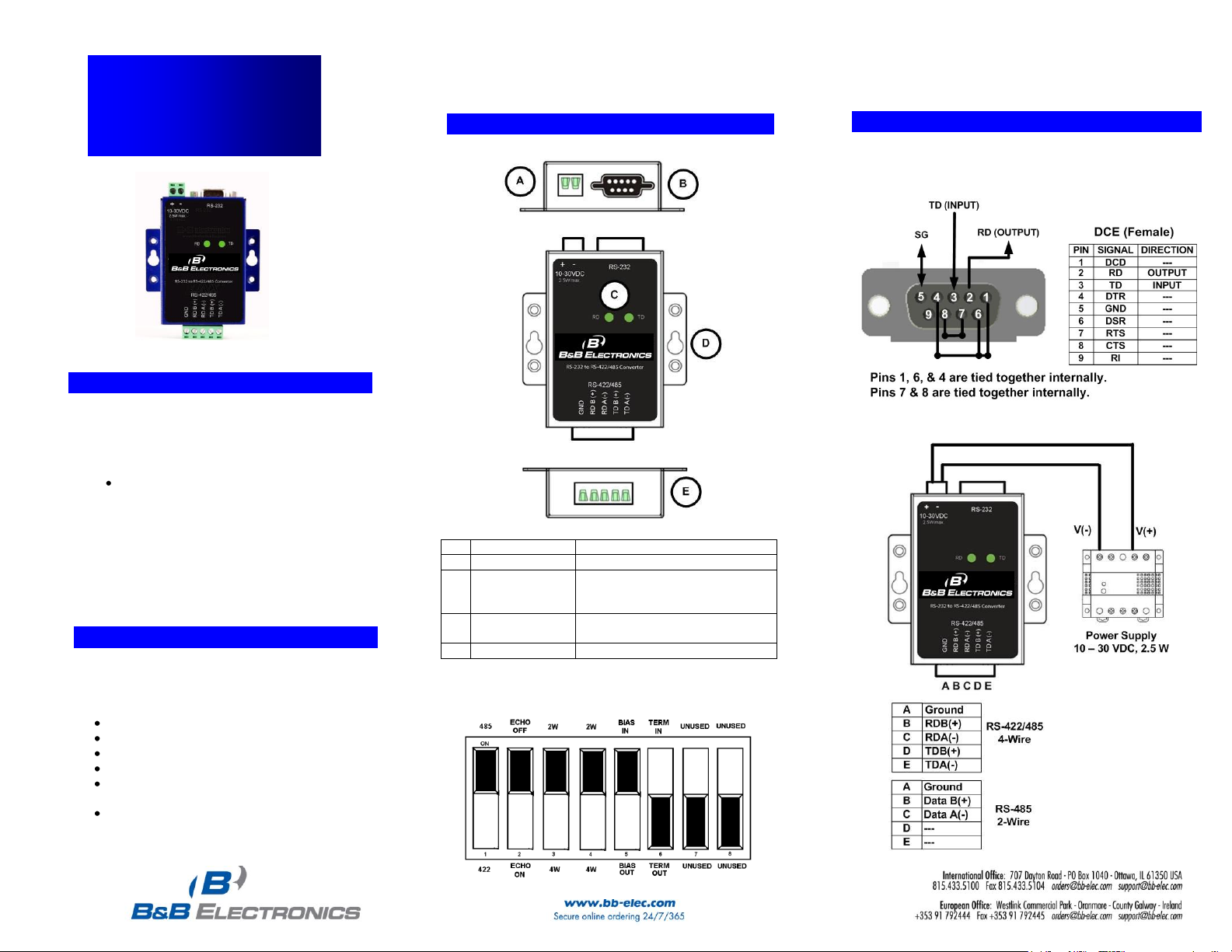
44.. PPiinnoouuttss && TTeerrmmiinnaall IIddeennttiiffiiccaattiioonn
DB9 Female Connector
Quick Start Guide
SCP211 & SCP311
RS-232 to RS-422/485
Converter
33.. CCoonnttrroollss && IInnddiiccaattoorrss
A
Power TB
Two Position, Removable
B
DB9 Female
RS-232 (Wired DCE)
C
Data LEDs
Green – ON when power is
applied. Blink to indicate data
flow
D
Mounting Ears
Used for Panel Mounting – Use
DRAD35 for DIN Rail Mounting
E
RS- 422/485 TB
5 Position, Removable
8 Position DIP Switch Located on Back
(Shown in default configuration)
©2011 B&B Electronics Manufacturing Company
Put
Page 2
Document Number – pn 9027 SCPx11-0712R002qsg
55.. PPoowweerr CCoonnnneeccttiioonn
1. Connect your external power supply to the two position
power terminal block (A). The polarity is indicated on the
front label. The converter will accept 10 to 30 VDC, 2.5W
Maximum.
2. The terminal block will accept 28 to 12 AWG Wire.
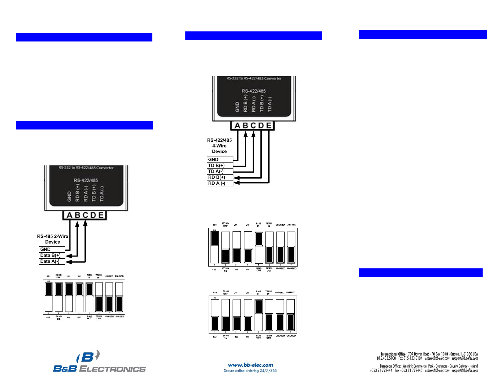
66.. WWiirriinngg EExxaammpplleess RRSS--448855 22--WWiirree
RS-485 2-Wire
1. In this example, the converter is set up to use internal
bias and no termination.
(NOTE: This is the default shipping configuration)
88.. BBiiaass && TTeerrmmiinnaattiioonn
1. The circuit can be biased using the built in 1 kΩ pull-
up and pull-down resistors. This is controlled with DIP
switch position 5. The default setting is ON (bias
resistors “in.”)
a. When an RS-485 network is in an idle state, all
nodes are in listen (receive) mode. Under this
condition there are no active drivers on the
network. All drivers are tri-stated. Without
anything driving the network, the state of the line
is unknown. If the voltage level at the receiver's A
and B inputs is less than ±200mV the logic level at
the output of the receivers will be the value of the
last bit received. In order to maintain the proper
idle voltage state, bias resistors must be applied
to force the data lines to the idle condition.
2. If Termination is necessary on the receive lines, a
built in 120 Ω resistor can be switched in using DIP
Switch Position 6. In most cases, termination is not
required. The default setting is OFF (termination
“out”.)
a. Termination is used to match impedance of a
node to the impedance of the transmission line
being used. Termination increases load on the
drivers, increases installation complexity, changes
biasing requirements and makes system
modification more difficult. Generally, termination
should only be used for long distances. “If in
doubt, leave it out.”
77.. WWiirriinngg EExxaammpplleess RRSS--442222//448855 44--WWiirree
RS-422/485 4-Wire
1. In this example, the converter is set up to use internal
bias and no termination.
RS-485 4-Wire DIP Switch
RS-422 4-Wire DIP Switch
99.. LLoooopp BBaacckk TTeesstt // TTrroouubblleesshhoooottiinngg
Configure for RS-485 Four wire
Jumper terminals B to D and C to E
Connect a PC to the RS-232 port
TD and RD LED’s are ON when power is applied.
Using hyper terminal or similar program, connect to
the appropriate COM port. Turn off hyper terminal
local echo
Transmit data. The same data should be returned.
When data is sent and looped back, the TD and
RD LED’s blink on and off indicating data flow
©2011 B&B Electronics Manufacturing Company
 Loading...