

Page 1

OP10
User Manual
A D C
Page 2

Contents
1 Summary ........................................................................................................................................1
1.1 Function ..............................................................................................................................1
1.2 General Specification..........................................................................................................1
1.3 Dimension...........................................................................................................................2
1.4 Installation...........................................................................................................................2
1.5 Components ........................................................................................................................2
1.5.1 LCD..........................................................................................................................2
1.5.2 Keys .........................................................................................................................2
1.5.3 Communication Ports...............................................................................................4
2 The Editing Software OP10-PCLINK............................................................................................6
2.1 General Introduction of OP10-PCLINK .............................................................................6
2.2 About the Project and Screen..............................................................................................6
2.3 Contents of the Screen ........................................................................................................6
2.4 Flowchart of Using..............................................................................................................6
2.5 Editing the User’s Screen....................................................................................................7
2.5.1 Create a New Project................................................................................................7
2.5.2 Making Basic Screen................................................................................................9
2.5.3 Configuration of OP10...........................................................................................10
2.5.4 Properties of OP10................................................................................................. 11
2.5.5 Text.........................................................................................................................12
2.5.6 Dynamic Text.........................................................................................................13
2.5.7 Function Keys ........................................................................................................15
2.5.8 Data Display...........................................................................................................18
2.5.9 Data Setting............................................................................................................21
2.5.10 LED......................................................................................................................24
2.5.11 Function Keys (for controlling the status switches).............................................25
2.5.12 Bar Graph.............................................................................................................26
2.5.13 Trend Line ............................................................................................................28
2.5.14 Alarm List ............................................................................................................29
2.5.15 Chief button..........................................................................................................31
2.5.16 Copy the value of registers form one device to other...........................................32
2.5.17 Preset dynamic text ..............................................................................................34
2.5.18 Preset register.......................................................................................................36
2.6 Save Project.......................................................................................................................38
2.7 Download Window ...........................................................................................................38
2.8 Importing .OPf Project......................................................................................................40
3 Manipulation................................................................................................................................44
3.1 Communication.................................................................................................................44
3.2 Changing the screens ........................................................................................................44
3.3 System Password...............................................................................................................44
4 Create new device ........................................................................................................................48
5 Communication............................................................................................................................57
1
Page 3

5.1. Communication port ........................................................................................................57
5.2 Communication connect....................................................................................................58
5.2.1 OP10 downloading cable ( write configuration screens ) ......................................58
5.2.2 Connect with TP03 (include SR type) PG port through RS-422............................58
5.2.3 Connect with TP03 through 485 port.....................................................................59
5.2.4 Connect with SG2 through 232 port (suitable for all types of SG2)......................60
5.2.5 Connect with SG2-V type with 485 port................................................................60
5.2.6 Connect with EV300 through 485 port ..................................................................61
5.2.7 Connect with SV300 ..............................................................................................61
2
Page 4

1 Summary
1.1 Function
OP10 is a Human-Machine Interface that is used with many kinds of PLC (or the other
intelligent controllers with communication ports). With OP10, both the values of the PLC inner
registers and the relays status of PLC can be monitored or changed through texts or LEDs. So the
operation of the machines or the devices is more easy and convenient.
OP10 programmable text monitor has many features:
The screens are made with the editor OP10-PCLINK on PC. Text including Chinese
characters can be input and the PLC address can be set. The screens are downloaded with serial
port.
The PLC communication protocols are downloaded to the OP10 with the data of the
screens, so the engineer don’t need to program of communication.
Support modbus RTU protocol.
Users can set 6 passwords, which have 3 levels.
Alarm list function. The current alarm information is displayed one by one.
It has 24 keys, which can be defined as function keys. There is a keyboard for numeric
input. The manipulation is simple. Some of the mechanic buttons on the controlling cabinet can be
substituted with them.
Various communication modes can be selected. Any of RS232, RS422 and RS485 is OK.
OP10 supports different screens in one project communicating with other devices through
different ports.
1.2 General Specification
Item Specification Remark
Power
Dimension 179.5*101.5*33 mm
Operation
Temperature
Height Not higher than an altitudes of
Environment
Relative
Humidity
Pollute level Pollute level 2 IEC61131-3-3.45.2
Mechanical
Running Status
Transport &
Storage
Condition
Shake
Strike 3 vertical directions 15g,11ms
Temperature -40℃~70℃
Height Not higher than an altitudes of
Fall down
freely
DC24V -15%~+10%
0℃~55℃
2000m
10%~95%,no dew
5≤f < 9 Hz 1.75mm range
shaking
9≤f≤150Hz 0.5g shaking
3000m
With production packing 0.3m
With transport packing 1m
1
Page 5
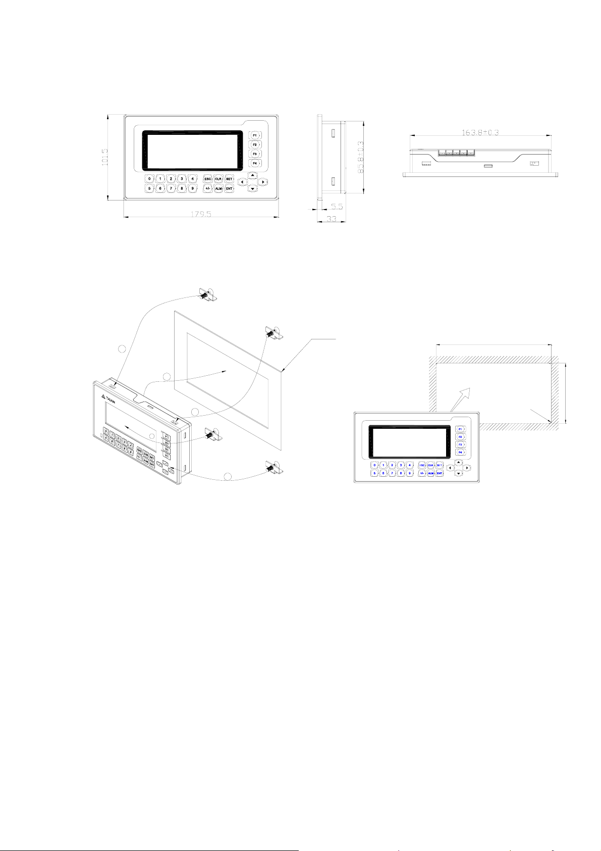
1.3 Dimension
1.4 Installation
TOP VIEW
Fix plate
2
1
2
2
2
1.5 Components
1.5.1 LCD
4.3” monochromic display, 192*64 pixels, olivine background.
165±0.25
R
87±0.25
2
±
0
.
5
1.5.2 Keys
On the front panel of OP10, there is a LCD display and 24 thin film switches. The keys have
a good touch feeling, and they are endurable and reliable. Besides being used for the basic
functions, all the 24 keys can be set for local functions or Chief functions.
2
Page 6

The basic functions of the function keys:
KEY Basic Function
[ESC]
[ALM]
[◄]
[►]
[▲]
[▼]
[SET]
[ENT]
When pressed, the OP10 will return to system initial screen. The user can
designate the system initial screen during the screen making procedure (default
value is screen no. 1, screen no.0 is prohibited). Usually the Main Menu screen
or the most-frequently-used screen is set to be the initial screen.
When pressed, the OP10 will shift to the predefined alarm list information
screen. It can also be defined as a specific function key.(If there is no alarm list
in the project, system function is ineffective.)
Left shift the digit being edited when changing the register data. When pressed,
the digit twinkling will be shifted to the left one.
Right shifting the digit being edited when changing the register data. When
pressed, the digit twinkling will be shifted to the right one.
Jump to the previous screen. The number of the previous screen is designated in
the Screen Attribute option (default value is the result of subtracting 1 from the
current screen number).
In the data setting mode, pressing it can add 1 to the digit being edited. The
value will increase from 0 to 9, then return to 0…… (DEC); increase from 0 to
F, then return to 0……(HEX)
Jump to the next screen. The number of the next screen is designated in the
Screen Attribute option (default value is the result of adding 1 to the current
screen number)
In the data setting mode, pressing it will subtract 1 from the digit being edited.
The value will decrease from 9 to 0, then return to 9……(DEC); increase from
0 to F, then return to 0……(HEX)
Press it to enter the mode for editing the value of registers. The register being
operated is displayed in reverse color. The digit being edited is flickeringly
displayed. If the current screen contains no register setting components, no
operation will be executed. When [SET] is re-pressed before [ENT] is pressed,
the edition done to the current register will be canceled. The user can continue
to operate the next data register.
NOTE: The function of register setting for [SET] can NOT be disabled by
the user-defined function.
When password protection is enabled, pressing it will pop up a screen for
password setting.
In register setting mode, pressing it means the edition on the current register is
finished. The edited data will be saved. Then the edition will move to the next
register. After the edition on the last register on the current screen has been
finished, it will quit from the register setting mode.
When pressed in the process of data input, you can clear the current data.
[CLR]
[+/-]
When you input the numbers with symbol, pressing it can change the symbol.
3
Page 7

0-9
F1-F4
Keys , which are user-defined for local-button function
All of the 24 keys can be defined for specific functions by users, for example, setting the
status of the coils, screen jumping, setting the registers, increasing by degrees, descending, etc.
Local button can be set in the current screen. It is effective only when the current screen is
displayed.
Keys, which are user-defined for Chief-button function
All of the 24 keys can be defined for specific functions by users, for example, setting the
status of the coils, screen jumping, setting the registers, increasing by degrees, descending, etc.
Chief button can be set under the tool menu. It is effective whatever which screen is
displayed.
The priority of the functions
When a key is user-defined for a specific function, it has many functions. But only when the
function which has the highest priority can be executed. Other functions are ignored.
Except for the [SET], [ALM] keys, the priority from high to low is: local buttonÆChief
buttonÆbasic function.
[SET], [ALM] keys, the priority from high to low is: basic functionÆlocal buttonÆChief
button.
The basic function of register setting for [SET] has the highest priority. So if there is a
function of setting register in the current screen, please don’t define [SET] for other functions.
Pressing [SET], after entering the setting function, all of the user-defined keys’ functions are not
effective until setting function is ended.
[ALM] key has the highest priority when there is a alarm list. So if there is a function of
adding alarm list, please don’t define [ALM] for other functions. Pressing [ALM] key, after
entering the alarm list, the user-defined local buttons are ineffective. [▲], [▼], [ESC] keys return
to their basic functions. Others hold the Chief button functions which have been defined before.
OP10 display has LED background light itself. As long as there is a key manipulation, the
background light will be on. Consumers also can set the background light always on.
1. They can be used as button controller, setting status of the coils, screen
jumping or editing the values of the registers
2. When users in the mode of editing the value of registers, the keys can input
values directly.
Chief control keys. Their basic function is switching screens, changing the
status of the coils and IO, editing the values of the registers, etc. The high-level
function is controlling the destination machine to be powered on or off, etc.
1.5.3 Communication Ports
OP10 has two communication ports: COM1 and RS485. COM1 is used for downloading user
programs, and offers RS422/RS232 port. RS485 offers RS485 port.
4
Page 8
COM1:
RS485:
Pin Definition Explanation
1 TX+ 422 send positive signal
2 RX 232 receive signal
3 TX 232 send signal
4 NC Interior used, can not be
connected with GND
5 GND 0 level
6 TX- 422 send negative signal
7 VCC 5V high level
8 RX- 422 receive negative signal
9 RX+ 422 receive positive signal
5
Page 9
2 The Editing Software OP10-PCLINK
2.1 General Introduction of OP10-PCLINK
OP10-PCLINK is the specific configuration software for the programmable text monitor
OP10. It can run on the SCREENS 98/2000/XP/vista platforms. It is easy to study and convenient
to use. The user can input English/Chinese characters directly.
2.2 About the Project and Screen
The basic element of a project is the screen. All the screens for one certain project are saved
in a single project file. Every screen is made to execute some certain functions. By arranging the
screens, the user can jump from one screen to another. The application project file is composed of
all the screens.
2.3 Contents of the Screen
After opening a project, users can create (“new”) or open (“open”) a screen. The user can put
some elements such as characters (English or Chinese), LEDs, switches, data inputting boxes and
jump keys on every screen. Jumping between different screens is allowed. The operator can carry
on the operations such as data monitoring, parameter setting, switch controlling, alarm list
monitoring and data transferring between registers of PLCs.
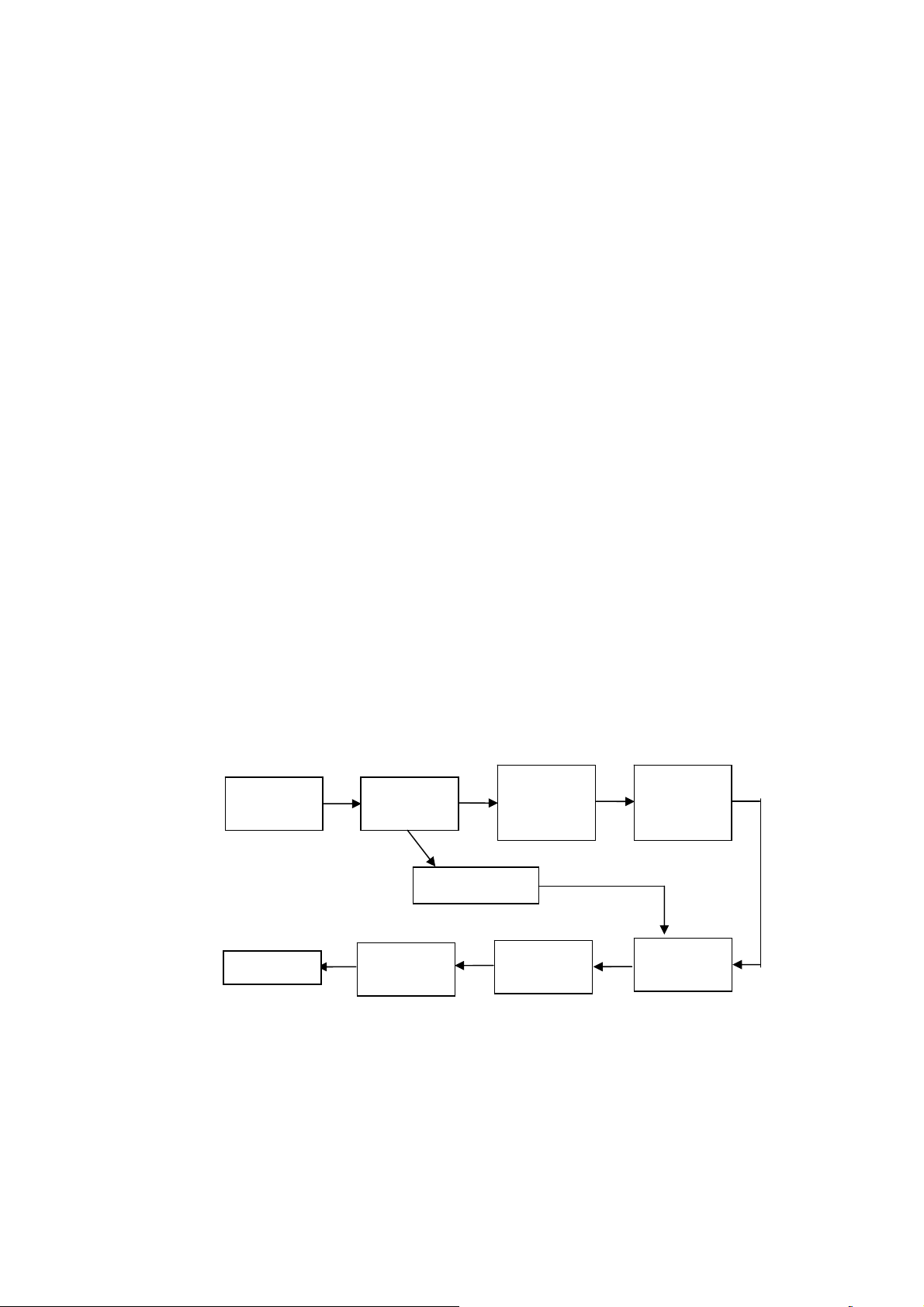
2.4 Flowchart of Using
The basic flowchart of using is shown in the following figure:
Software
installation
Run
Run the
software
Read OP10
Download
the screens
Create or
Open a
project
Save the
project
Create or
Open a
screen
Edit the
screen
6
Page 10
2.5 Editing the User’s Screen
2.5.1 Create a New Project
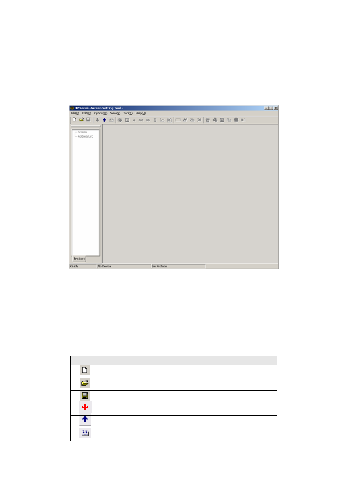
Run the software OP10-PCLINK and create a project, after which a screen editor will be
showed on the screen.
The screen-editing region is on the center of the editor. There is a grid of white dots in the
display region. The distance between every two rows and two columns is 16 points. The whole
region is a matrix of 192*64 points. The user can refer to the dots nearby to align the components
when laying or moving them. When necessary, change X and Y positions of the components to
locate them in arbitrary positions.
The table below is the description of all the buttons in the toolbar:
Button Function
Create a new project
Open project
Save project
Download the configuration project to OP10.
Upload the project inside OP10
Translate and edit the project, show the information of the project.
7
Page 11
New screen, pressing the key “New” in the screen indicator will also
new a screen.
Edit the attribute of the screen
Change a screen with the copy of another one
Delete the current screen
Designate the initial screen. When the display is running, the system
will return to the initial screen directly if [ESC] is pressed. Usually
the main menu or the screen most-frequently used is set to be the
initial screen; set the system password; set the definition number of
the interactive controlling register.
Login the Alarm List information. Every piece of information
represents a status of the select variable.
Set Chief button
Change the data of the registers with the copy of another device.
Preset dynamic text
Preset register
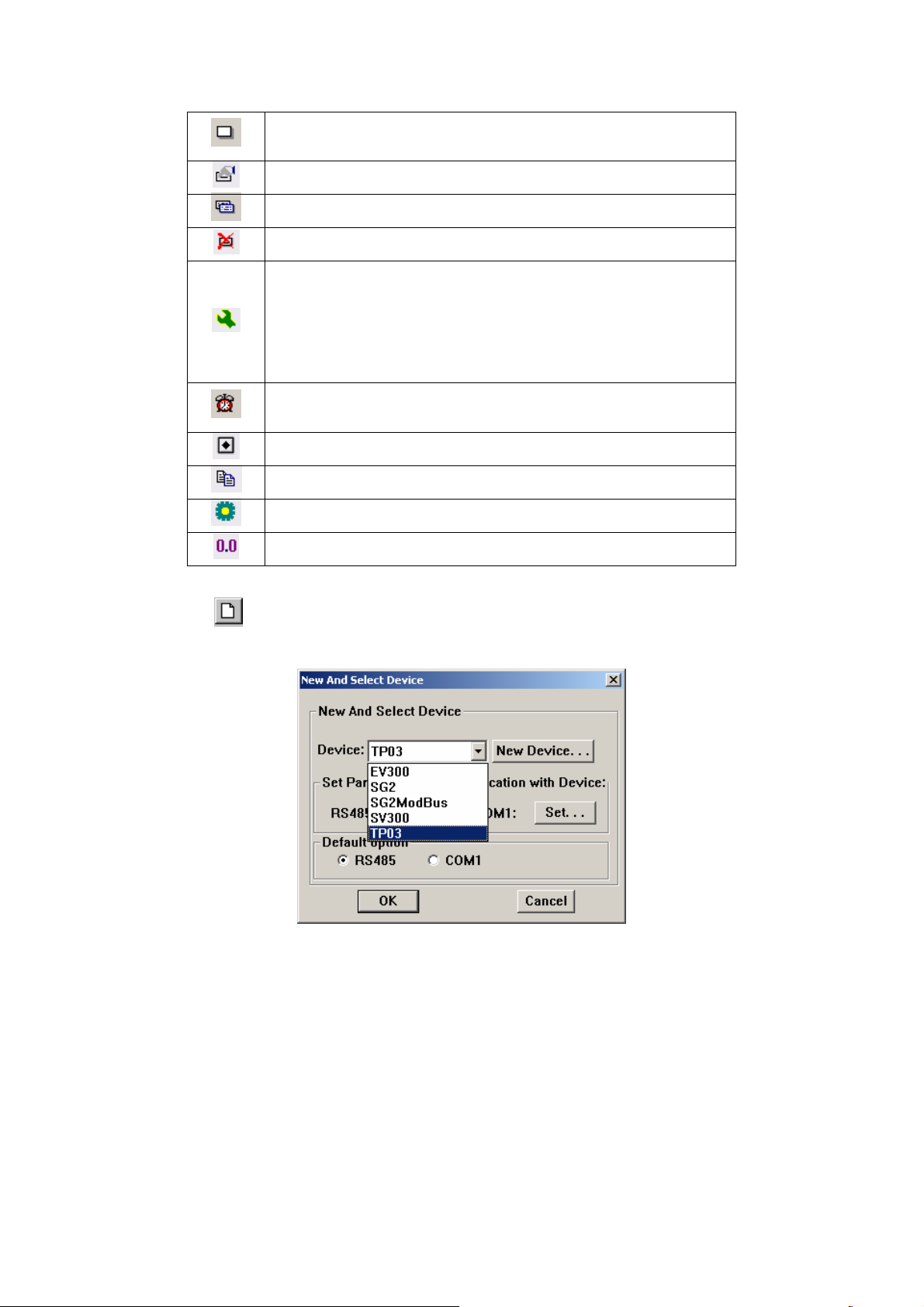
Press
selection:
Select the proper PLC type. Then click “Set” button down beside the port name to set
communication parameter.
or activate [File]→[New] command in the menu to pop up a dialog box for PLC
8
Page 12

Select the proper baud rate, data bits, stop bits, parity and communication port in the dialog
box. OP10 supports the function that two communication ports can connect with different PLCs
and transducers using different communication formats.
Selecting the proper PLC type which bases on the destination controller. When
OP10-PCLINK downloads (writes) the screens, it sends the appointed PLC communication
protocol and the data of the screens to OP10 all together. When the display is running, it
communicates with PLC through the protocol.
2.5.2 Making Basic Screen
In the example given below, the PLC type is TP03. The example will give you a general
description of screen making.
Firstly, enter the system initial screen (default value is screen no.1) editing mode. The
properties of the current screen (screen no.1) are shown at the right and bottom edge of the
interface. Every screen has its own properties, which include 4 items:
Screen Description:
Descript the use of the screen. It helps the designer to note the use of all the screens.
(can be omitted),for example:“ main menu”
When Up Arrow key ([▲]) pressed, jump to screen:
The number of the screen that it will jump to when Up Arrow key pressed.
When Down Arrow key ([▼]) pressed, jump to screen:
The number of the screen that it will jump to when Down Arrow key pressed.
Choose communication port:
OP10 supports every individual screen choosing its own communication ports.
The most convenient way for screen jumping is to press [ESC], [▲] and [▼] when the OP10
is running. The user can also jump from one screen to another by pressing the user-defined
function keys.
Note:
If the [▲] and [▼] key in the current screen are defined for other functions, the screen
jumping parameters of the screen properties are invalid.
If the screen designated by the [▲] key doesn’t exist, the system will search up until the
existing screen is found and jump to it. It will stop at screen 1 if no screen is found. The
situation of the [▼] key is similar, that means the system will search down for the
screen if the designated one doesn’t exist..
9
Page 13
If there are some data setting components in the screen, [▲] and [▼] key will execute
the function of value increase and decrease in the data setting mode. After quitting the
data setting mode, the [▲] and [▼] key will execute the basic function for screen
jumping.
Choose the communication port of the screen. Users can choose COM1/485 port as the
communication port of the current screen. Users also can set the COM1/485
communication port of OP10 to demand the data of different destination host at the
same time.
For example: Screen 1 can be set as communicating through 232; Screen 2 can be set as
communicating through 485.They are separate.
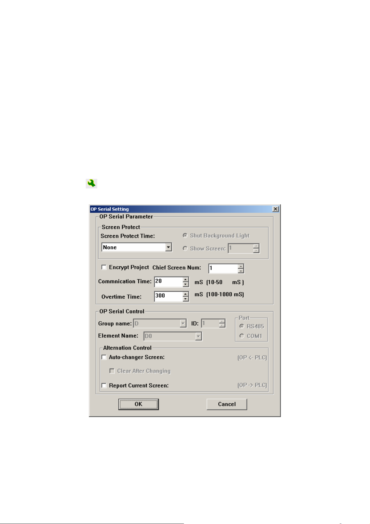
2.5.3 Configuration of OP10
Press
or activate [Tools]→[OP10 serial Set] command to pop up a dialog box for
configuring the system parameters of OP10:
Initial Screen
The first screen will be displayed after power on. Usually this screen is set to be the
main menu screen or the most-frequently-used screen. Press [ESC] when the OP10 is running,
the system will jump to this screen directly.
Screen Saver
Under default conditions, the backlight is set to be “never”. The time can be set by the
10
Page 14
user. If it is set to be “never”, the backlight will keep on. Also, the screen can be set to jump
to a screensaver screen when no key is pressed in configurable time.
Note: If the screen has jumped to a screen saver screen, the pressing of any key will not carry
out any function. Any operation will awake the screen saver to return to the original screen.
OP10 serial Status Control
Usually the screen changing is executed by pressing the keys. Besides, the PLC can
change screen by changing the data in register. If this property is selected, the number ‘n’ will
be written into the D300 (for example) controlling register at the beginning of running, then
OP10 will jump to screen No.n. OP10 write the current screen no. into D301, so PLC can
know the status of the status of OP10. (Users can choose the function to clear the register in
the screen. After jumping to that screen, the data in controlling register will be cleared.)
Note: The user can define the address of the interactive controlling register.
Encrypt the project
Users can upload the project from OP10 to Pc and edit it. If the users hope the
configuration screens in the production can’t be uploaded illegally, they can choose this
option. After choosing the option, although someone has the highest level password in the
project, he can’t upload the data.
Communication time
Communication time is the interval between OP10 sends two communication commands.
Its value can be set between 10ms-100ms. If the corresponding controller answers fast, the
communication time can be reduced. On the contrary, increase the time. Under the default
condition, OP10 sends communication data every 20ms.
Overtime
The time decides when OP10 demanding data overflows. Some controllers read data fast,
but take a long time to write data. At this condition, users can set the longest write time as
overtime to avoid data setting errors when increase data of register by degrees.
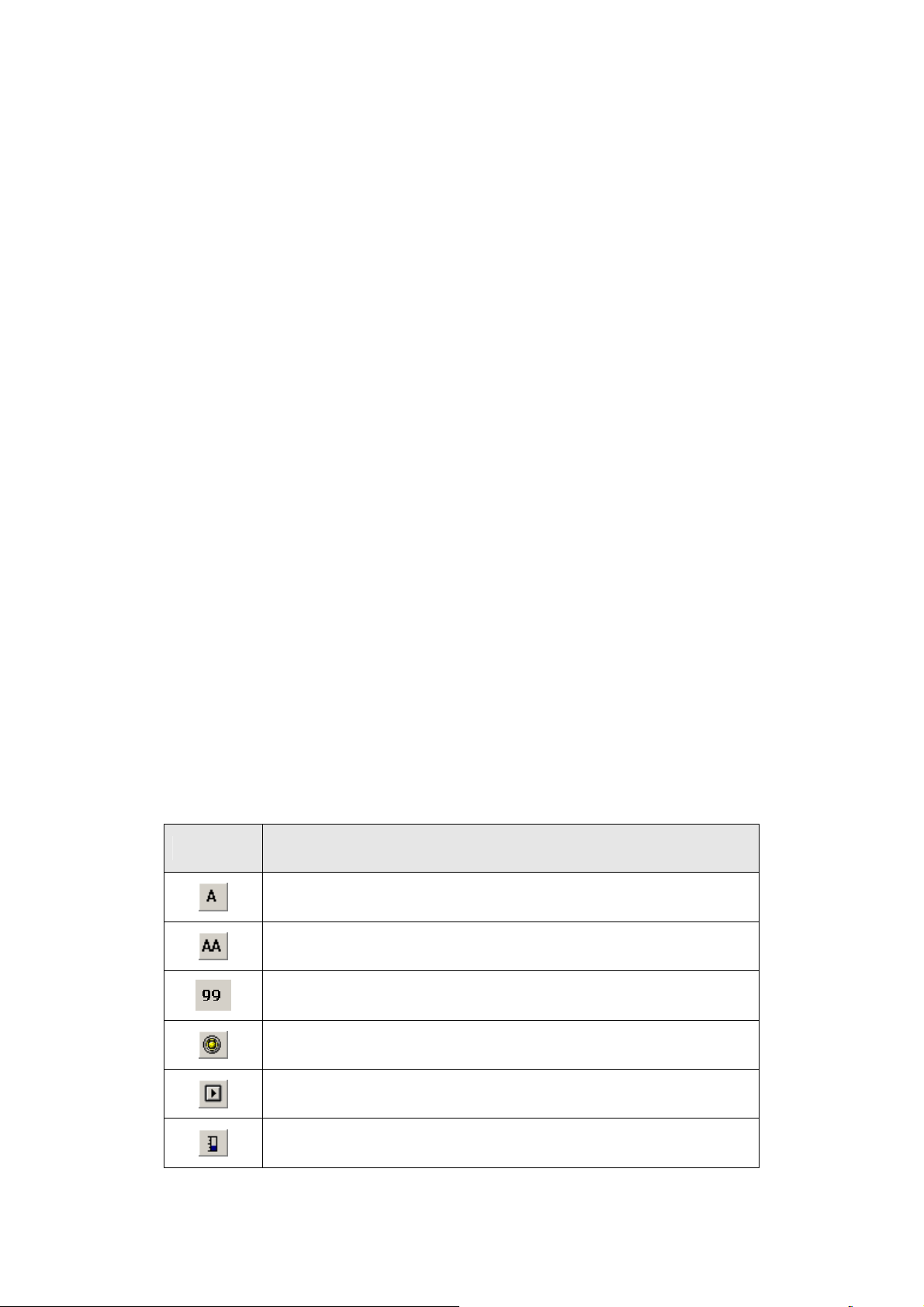
2.5.4 Properties of OP10
Component Function
Input text, including Chinese characters and English letters.
Dynamic text list. The content of the text can be changed under the
control of PLC register.
Register components. The user can dispose some data setting/monitoring
components with it. (the relate address are the PLC registers)
LED indicator. Indicate the on/off status of the inner delays in PLC.
Function key. All of 24 keys can be defined to be function keys. They
can execute the functions such as screen jumping and switch control.
Bar graph. Monitor the data change in PLC in the form of bar graphs.
11
Page 15
Trend line. Monitor the data change in PLC in the form of trend lines.
Paste pictures. Paste a monochrome BMP picture (Max. 192×64 pixels)
onto the screen.
Alarm list. Users can set 8 groups of alarm lists corresponding to 8
different hosts at most. There are at most 32 pieces of alarm information
in each group.
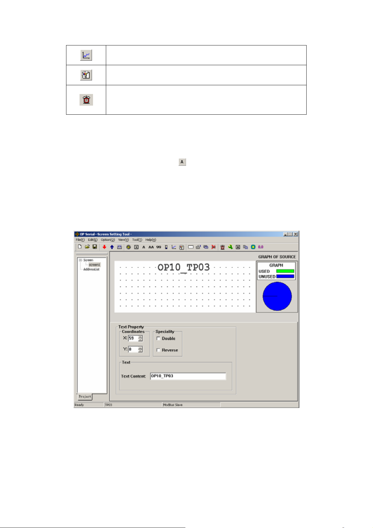
2.5.5 Text
The example below shows how to design a main menu screen as the screen no.1.
Firstly, lay the text “Main Menu”. Press
and click the left button on the editing region to
affirm the operation (right click will cancel it). After left click, the default text “TEXT” will be
displayed in the editing region. The properties of the text are displayed below the editing region.
The text string will move as the user moves the cursor. To locate the text in an arbitrary position,
edit the X and Y coordinates. Changing the content of the text to “OP10_TP03”, the
corresponding text string will be displayed in the editing region.
Coordinates
X value represents the horizontal position of the text string.
Y value represents the vertical position of the text string.
The origin of the position is the up-left corner of the screen.
Speciality
Double: The text will be displayed in double size, both horizontally and vertically.
Reverse: The text and the background will be displayed in reversed color.
12
Page 16
Tex t
The content that will be actually displayed is input here. The user can input English
letters or Chinese characters with various kinds of Chinese input methods in this textbox. The
content in it can be copied or pasted.
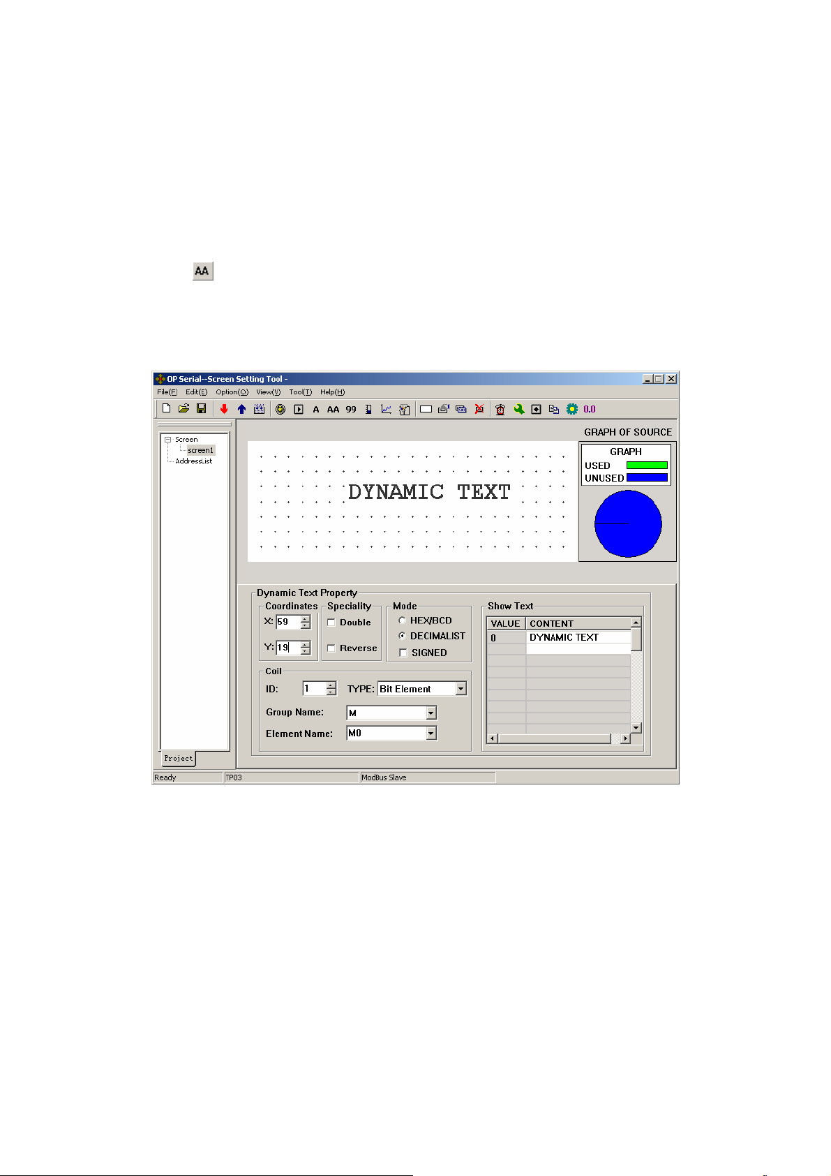
2.5.6 Dynamic Text
Press
and click the left button on the editing region to affirm the operation (right click
will cancel it). After left click, the default text “DYNAMIC TEXT” will be displayed on the
editing region. The properties of the dynamic text are displayed below the editing region. The text
string will move as the user moves the cursor. To locate the dynamic text in an arbitrary position,
edit the X and Y coordinates.
Coordinates
X value represents the horizontal position of the text.
Y value represents the vertical position of the text.
The origin of the position is at the up-left corner of the screen.
Speciality
Double: The text will be displayed in double size, both horizontally and vertically.
Reverse: The text and the background will be displayed in reversed color.
Coil
The PLC data register for controlling the status change of the dynamic text.
Mode
Determine the data form of the data register. The form will affect the display form of the
numeric items in the dynamic text.
Type
13
Page 17
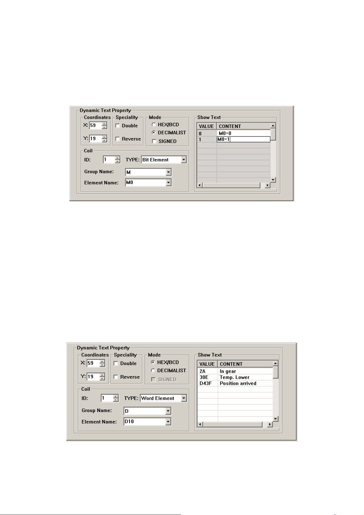
Users can choose “Bit element” or “word element”.
When users choose bit element, dynamic text relates with the status of the select
variable inside the PLC. The corresponding text can be set to 0 or 1, two kinds of status .
The picture below shows bit text:
When M0 is 0, the dynamic text shows “M0=0”. By contraries, it shows “M0=1”.
If the dynamic text corresponding to word element, it can keep the texts corresponding
to as many as 32 different statuses.
Display Text
Log the different text content corresponding to different values of the data register. It
can keep the texts corresponding to as many as 32 different statuses. The value of the text can
be inconsecutive. Consumers can input the value themselves.
Example: Display the dynamic text controlled by register D10. The dynamic text to be
displayed has three statuses: “In gear”, “Temp. Lower” and “Position arrived”. The three
texts correspond to the D10 register value 2a, 30e and d43f (HEX form) respectively. Input
“2a” in the “Value” space of the first row and “In gear” in the “Context” space on the right.
Input the other two statuses in the same way. If the value of register D10 is 2a, the dynamic
text be displayed is “In gear”. If it is 30e, “Temp Lower” will be displayed. Other conditions
can be inferred from the two examples above. The example is shown in the figure below:
14
Page 18
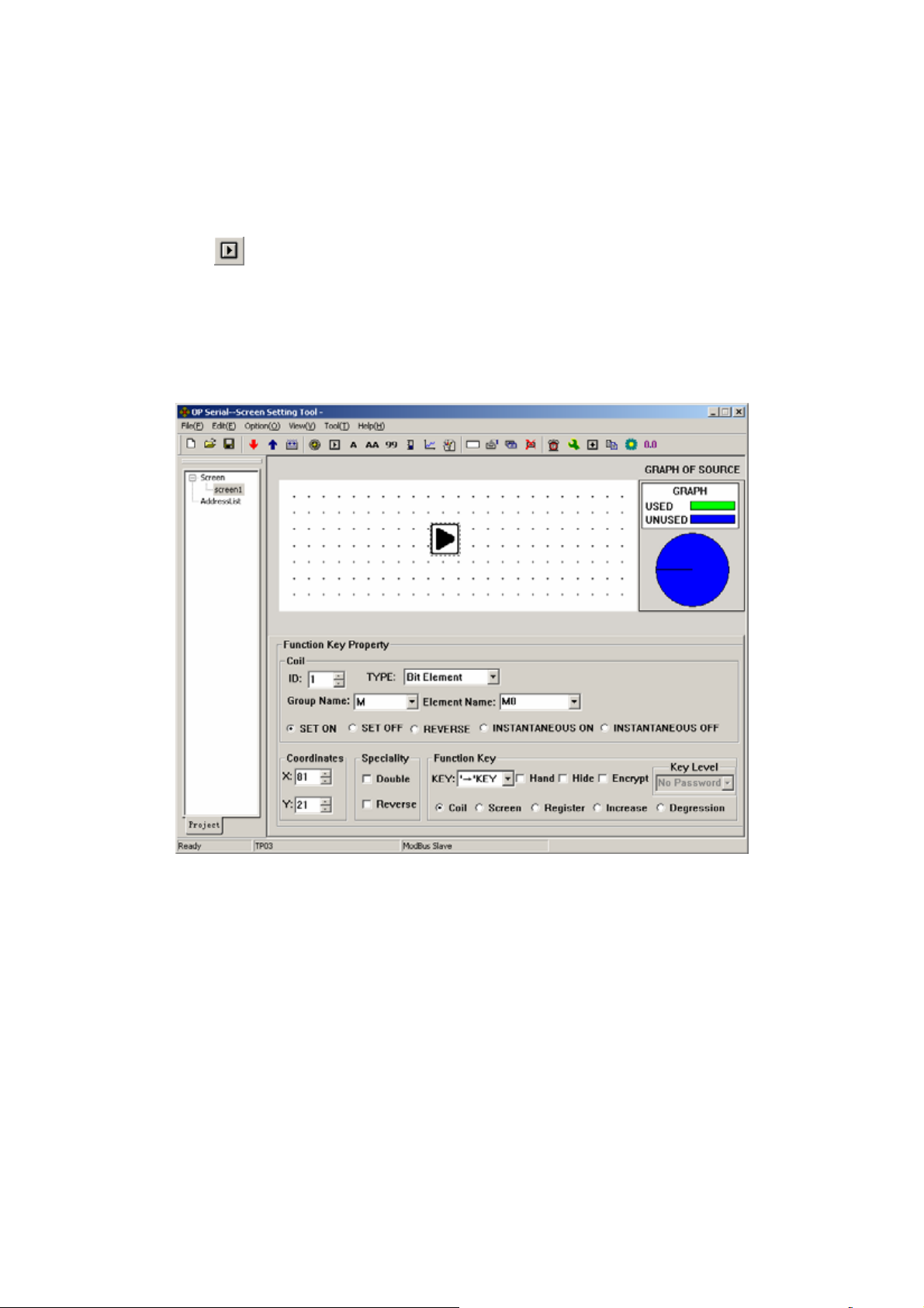
2.5.7 Function Keys
Next, configure the function keys in the main menu screen to execute the function of screen
jumping (for example, press [◄] to jump to the parameter setting screen; press [►] to jump to the
mode setting screen). The procedure of defining the function keys is:
Press
to activate a dotted rectangular box. The box moves as the cursor moves. Click
the left button to determine the position of the function key. A hand shape and the function key to
be defined (default key is [►]) are displayed in the editing region. The properties of the function
key are displayed below the editing region. The meanings of position and style are the same as
those in the text property. They indicate the position,the size and the color of the graph.
The function key setting screen is shown in the figure below:
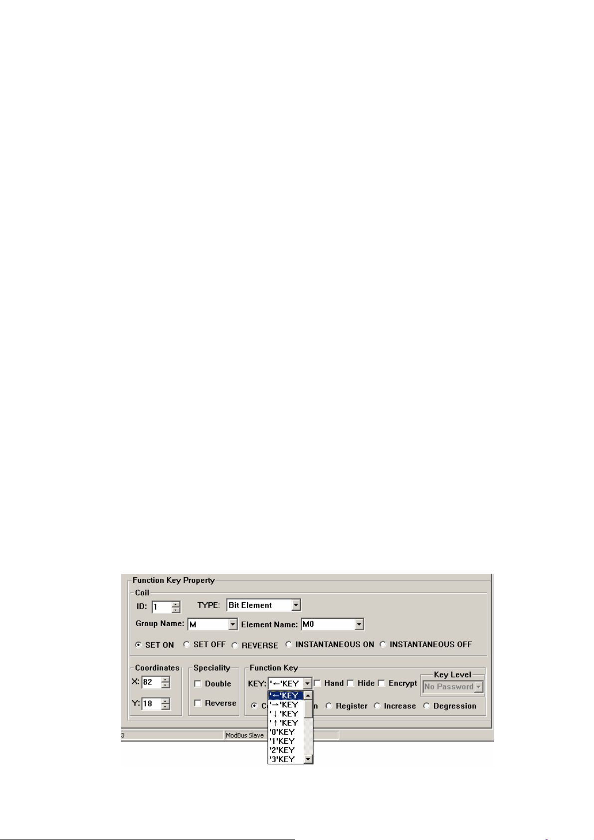
Key
Select a proper key from the 24 keys. Do not conflict with system keys.
Hand
For the convenience of use, add a hand shape symbol before the key symbol. The hand
indicates that pressing the key will carry out an operation. The user can remove the hand
shape to save the space.
Hide
The user can make the symbols of some keys invisible in the screen. But the functions
of those keys are still valid.
Encrypt
Only when the system password is entered correctly, the function key can execute its
function.
Coil
The function key is defined to set a switch.
15
Page 19
Screen
The key is defined to execute the screen jumping function.
Register
The key is defined to set the register parameters.
Increase
The value of the destination register will increase an appointed constant in the range of
user-defined.
Degression
The value of the destination register will decrease an appointed constant in the range of
user-defined.
ID
The station number of PLC
Type
When the key is defined to set a switch, the definition number of the PLC relay
corresponding to the switch is determined by the type here.
Group name & Element name
Set the address of the relay.
Set ON
Set the designated relay on.
Set OFF
Set the designated relay off.
Reverse
Set the designated relay to be of negative logic.
Instantaneous on
The designated relay will be set on when the key is pressed down. When the key is
released, the relay will be set off.
Instantaneous off
The designated relay will be set off when the key is pressed down. When the key is
released, the relay will be set on.
Click the down arrow on the right of the list to show the names of the 24 keys. Select the
proper key to be defined.
16
Page 20
To make the screen simple, the hand shape can be removed by not selecting the checkbox
“Hand”. So only the keys are shown on the screen. Select the option button “Jump to” to define
the key as a screen jumping function key. Designate the target screen number below the key. If the
number is 10, it means screen no.10 is the parameter setting screen.
To hide the parameter setting screen, select the checkbox “Password” to enable the password
property. Thus the system will jump to screen no.10 only when the password entered has the same
or higher priority and it is correct.
After setting the function key, put the text “set parameter” beside the key symbol to inform
the operator that it will jump to the screen for parameter setting when [►] is pressed.
Note: To leave some margin for inserting new screens, the number of different kinds of screens
should be non-continuous.
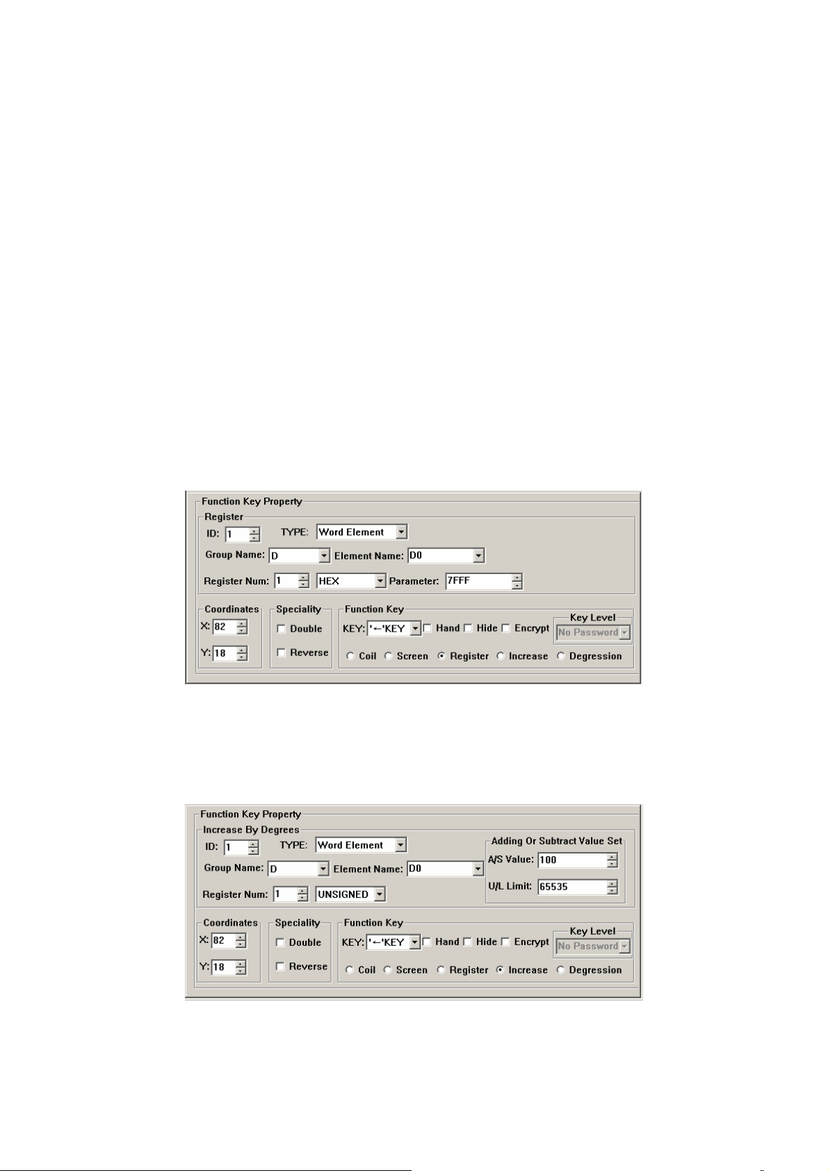
Setting register parameter with a single function key:
To write a parameter (or constant) to a designated register, select a function key from the key
list and select the option button “Register”. The constant parameter will be written to the
designated register when that key is pressed during running. Setting as the following figure will
write the hexadecimal number 7FFF to the D register at address 0.
Increasing the constant of the register with a single function key:
To increase a parameter (or constant) to a designated register, select a function key from the
key list and select the option button “Increase”. The constant parameter will increase by degrees
until reach the upper limit value. The example below can let the register D0 add 100 every time
when the key pressed, the upper limit value is FFFF (Hex).
Degression is similar. Users should set the lower limit value. Under the default condition, the Min
limit value is 0.
17
Page 21

2.5.8 Data Display
This section will introduce how to make a Set parameter screen. The methods of setting the
components such as parameter display, parameter setting and password setting are discussed in
detail.
The procedure of making the screen:
Click [Tool]→[New Screen] or click the screen description to pop up a dialog box for setting
the screen number and the screen description.
Screen Num:
The serial number of the new screen.
Screen Description
Descript the character of the new screen.
Click the blank of the screen editing region or click the screen description in the left of the
dialogue box to pop “Screen Property” dialogue box of the current screen.
“Up”/“Down” Key To Screen:
Choose the screen which to jump to when the [▼]/[▲] key pressed.
Option
Choose the communication port of the current screen. OP10 supports different screens
in one project communicating with other devices through different ports.
Put the data display boxes. Press
to show a rectangular dotted box moving with the
cursor. Click the left button in the proper position. The number “12345” in the dotted box
indicates that this component is a five-digits register displaying/setting box.
18
Page 22

The properties in the dialog box are:
ID
The definition number of the PLC register corresponding to the display component.
Register num
It is the amount of the registers being displayed or set. The minimum number is 1, and
the maximum is 2.
Encrypt
If selected, the data can be changed only when the correct system password is entered.
The command for setting the password is in the menu “Tools(T
)”.
Show
Input Digit
The maximum number of digits of the data being displayed or set
Point Digit
The length of the significant digits behind the decimal point
Indent Manner
Right Indent. When users only want to show the high bit, right Indent can be chosen.
Left Indent. When users only want to show the high bit, left Indent can be chosen.
Example: The presettable value of T register of SG2 is from 0 to 99999. Users can
choose 4 bits to show, left indent, ignore high bits. Now, the value is from 0 to 9999.
Decimalist.
The data in the register will be displayed in decimal form.
Signed
Only valid when the “Dec.” mode is selected. If the highest digit of the register is 1, the
data will be displayed as a negative number. For example, the hexadecimal number FFFEH
represents –2.
HEX/BCD
The data is displayed in hexadecimal form.
Set
The component can be used for setting data if it is selected. So the component can be
used for both monitoring and setting the data. The register set box has some special
properties: maximum, minimum and password.
Project data
Project data shows proportional data.
Example 1:
Set A output as below:
Group name= D; Element name= D0; Register Num= 1; Input Digit= 5; Point Digit= 0;
Decimalist; not show the negative.
19
Page 23

Use the same method to set the current screen, which shows the output of B. The register
address is D1. Other properties are the same as A.
After downloading the configuration screens from PC to OP10, OP10 will demand the value
of D0 and D1. Then the value will be displayed on the screen in time. Users only need to put the
output of A in D0, B in D1. They do not need to care the communication between TP03 and OP10.
Example 2: Project Data
If the input voltage of TP03 AD module voltage is 0-10V, the value of the corresponding
register is 0-1023 and that users only want to show the current voltage, users can set project data.
Suppose the corresponding register with AD is D0.
20
Page 24

The Converted Data= (original register data – Min Input) * (Eng. Max – Eng.Min) / (Max
Input – Min Input)
2.5.9 Data Setting
Continue the configuration of the parameter-setting window. Press
to show a dotted
box moving with the cursor. Move the cursor until the proper position is reached, then click the
left button to confirm the position. Select the “Set” checkbox. So the component has the function
of monitoring and setting the data.
If the “Set” checkbox is selected, two additional options, “Encrypt” and “Upper/Lower
Limited”, are enabled.
Encrypt
To enhance the security of the device, the operation of parameter setting can be
protected by password.
To set or change the password, activate the command “Tool(T)”→ “Encryption lever
set” to pop up a dialog for password setting:
21
Page 25

Enter a new password, change the original password or set the priorities of the passwords.
For example, enter “5678” , choose the priority “Mid-Level” and click “Ok”. Then the password is
affirmed.
There are at most 6 passwords which can be set in OP10. Those passwords are classified into
3 ranks. “High-level” has the highest priority with “Low-Level” having the lowest. For example,
if one specific key need a “Mid-Level” password to react, now inputting “Low-Level” password is
useless. You can input “Mid-Level” or “High-Level” password to run this function.
When the operator press the key [ENT], the OP10 will pop up a password enter window.
Appointed data can be changed only when the priority of the entered password the same as or
higher than the one of the registers, users can modify appointed data.
The password is effective only once. Users need to input the password again, when they want
to modify the data for a second time.
Limit Set
The designer can set limits to the data to make the data out of limits invalid. Thus the
possible damage done by inputting data too great or tiny is avoided. For example, let the
maximum input be 9000 and the minimum be 0. The setting value will be written into the
register only when it is between 0 and 9000, or the system will halt until a correct value is
entered.
Original and Project data
After selecting the “Limit Set” checkbox, the designer can select the original data or the
project data from the list.
Original data
The original data option means that the data in the register will be displayed without any
operation. The position of the decimal point is determined by the value of the “Decimal”
22
Page 26

property. For example, if “Decimal”=2 and the register value is 14561, it will be displayed as
14561
Project data
This option means that the data read from the register will be converted to project data
before being displayed. The conversion is done following the formula below:
The Converted Data= (original register data – Min Input) * (Eng. Max – Eng. Min) /
(Max Input – Min Input)
Users can use project data in such conditions, for example:
AD real input is 0-1023. But users want to show the data as 0-10V.
Calculate the new data which according to the input of project data.Then modify the
value of corresponding register inside the PLC to the new data. Etc.
Example: Users should set 0-10V to correspond with the AD inputting register D0(0-1023).
Set as below:
When user set 10, the value of D0 is 1023.
When user set 0, the value of D0 is 0.
The value of D0 (original register data – Min Input) * (Eng. Max – Eng. Min) / (Max Input –
Min Input)
23
Page 27

2.5.10 LED
Create a new screen like this:
Press
to put a LED. There is a dotted box moving with the cursor in the editing region.
Click the left button in the proper position to locate the LED.
Coil
The definition of the PLC intermediate relay that is corresponding to the LED
Shape
The shape of the LED, round and square.
Positive Logic
The LED is filled when the corresponding intermediate relay is ON. Unfilled when the
corresponding intermediate relay is OFF.
Negative Logic
The LED is unfilled when the corresponding relay is ON. Filled when is OFF.
24
Page 28

2.5.11 Function Keys (for controlling the status switches)
Press
to activate a dotted rectangular box. The box moves as the cursor moves. Click
the left button to determine the position of the function key.
Select button
. Set the attribute as below:
It means the status of coil M0 is reverse when
is pressed
25
Page 29

2.5.12 Bar Graph
The bar graph can give a direct view of some analog parameters such as flow rate, pressure
and level. The user can set the height, width and the direction of it arbitrarily.
Press
to show a dotted box that moves with the cursor. Move the cursor to the proper
position and click the left button to locate the bar graph there.
Register
The address of the register corresponding to the bar graph
Full Value
The register value corresponding to the full bar graph
Zero Value
The register value corresponding to the empty bar graph
Direction
The direction of the bar graph, including four options: up, down, left and right.
Size
The height and width of the bar graph
The next example shows how to use bar graph to show the pressure.
26
Page 30

The bar graph demands the data in D0.When the bar is full, it means the data is 1000 in
D0.When the bar shows the scale of 500, it means the data is 500 in D0.
Bar graph shows data directly. And it is real-time updating. It’s fit for showing pressure,
voltage or other signals like these.
27
Page 31

2.5.13 Trend Line
Some parameters in industrial control applications vary at a slow rate. Often, the operators
want to know the variations of these parameters in a certain of time. Trend line should be the best
choice.
Press
to show a dotted box that moves with the cursor. Move the cursor to the proper
position and click the left button to locate the trend line there.
Register
The address of the register corresponding to the trend line
Full Value
The register value when the trend line reaches the 100% of the scale
Zero Value
The register value when the trend line reaches the 0% of the scale
Data Collection (number of dots)
The total of the sample points in the whole trend line. The more sample dots does the
trend line has, the more detail it can provide. Certainly more sample dots make the time
period longer. The largest number of the dots is the width of the trend Line minus 2.
Timing Interval
The interval between two sample points . Max: 65535 seconds, Min: 1 second
Size
The length and width of the trend line. Max: 192*64 point, Min: 16*16point
Note:
1. A trend line component can display only one line.
2. There is no limit to the amount of the trend lines on the screen. But the amount of data
collection can’t be more than 384 on one screen.
3. The newest data is appeared on the right side of the trend line. When a new data comes,
other former data move to the next left grid.
28
Page 32

2.5.14 Alarm List
In industrial auto-control applications, alarming is a very important function. It can be used in
many cases. Alarm list is the most direct and simple method.
Every project of OP10 can have a cluster of alarm list information. Every piece of
information corresponds to a relay. The addresses of all the relays are continuous. The user can
designate the initial address of the relays. When any of the relays jumps from OFF to ON, the
corresponding alarm information is activated. OP10 will pop up the alarm window, where the
alarm information is displayed in the first row. If another relay jumps to ON, the new information
will be displayed in the second row. When some alarm relay jumps to OFF, the corresponding
alarm information will disappear automatically.
To log the alarm information, press
to pop up the alarm list dialog box:
The list is blank for no information has been logged. Move the cursor to the “Alarm
description” column and enter the information “Temp. too high”. Press “Enter” to show the screen
as the following figure:
29
Page 33

Input other information in the same way.
After entering all the information, set the coil type and address to M0 (for example) to
indicate that the relays M0-M2 correspond to three pieces of alarm information.
When OP10 is in gear, if M0 and M1 are set ON, it will pop up an alarm window and display
as the figure below shows:
Seeing this alarm window, the operator can take some measures to solute the breakdowns. To
return to the monitoring window, press [ESC]. When OP10 is displayed a common screen, users
can press [ALM], if they need to inquire about the status of the alarm information of current
destination controller. Then system will jump to the alarm screen.
30
Page 34

2.5.15 Chief button
Click
in the toolbar to pop a Chief Button dialogue box.
Click [New] to add “Å” button. Set the function as “set M0 on”.
The button of OP10 can be set for chief function. The priority order from high to low is:
basic function > local button > Chief button. So if there is a [Å] on the screen, OP10 will execute
the function which on the current screen when the button is pressed.
31
Page 35

2.5.16 Copy the value of registers form one device to other.
Click
in the toolbar to pop a Copy Register dialogue box.
Users can set 3 groups of relationships about registers transferring. Every communication
scanning cycle, OP10 will check the synchronization between source PLC and those of destination
PLC once. If source PLC has communication errors, OP10 won’t update the registers of
destination PLC. Every corresponding relationship contains one group of source addresses, 5
groups of destination addresses and can transfer 16 seriate word registers (not support double
words register transfer) at most.
Click “New” Button. An “Add Register” dialogue box will be popped.
Set the attribute of the register:
Example: Copy the content from D0-D10 of ID1 to D20-D30 of ID2.
32
Page 36

It doesn’t matter that source PLC and destination PLC are not on the same bus. OP10 can use
download port to communicate with source PLC, then send the data of registers to the destination
PLC through 485 bus. Users only need to choose the communication port in the dialogue box
simply.
33
Page 37

2.5.17 Preset dynamic text
In the example given below, the PLC type is TP03. Establish a new project, choose SV300 as
the device.
Click
in the toolbar to pop a dialogue box like this:
Set the relationship between the status of CMD component (Operation) and the dynamic text:
Choose the type “bit element”. Element name is “Operation”. When users use dynamic text
in the project, the relationship which is preset will be loaded automatically.
34
Page 38

Presetting dynamic text can correspond Chinese characters with the function of the registers.
It can help the users to be familiar with the registers inside the PLC quickly.
35
Page 39

2.5.18 Preset register
Example: SV300
Click
in the toolbar to pop Preset Register dialogue box.
Some register value has its own prescriptive format, such as the “Set Frequency” register of
SV300. If we set the value of the register as 50Hz, the real value of the register is 5000. Using the
presetting, we can set the actually frequency to be the same with the value which we set. Both of
them
are 50.
Set “Set frequency” register as the following picture.
Now if users put “Register components” in the editing region. Choose “Set Frequency”
register. The picture below will be shown on the screen:
36
Page 40

It is convenient for users to use Register components to control registers with prescriptive
format.
37
Page 41

2.6 Save Project
Press or ckick [File]→[Save] to show the save dialog box:
Select the proper path and filename to save the file. The system defines “opf” as the default
external filename.
Enter the filename and select the proper path, then click “Save”.
2.7 Download Window
Connect the 9-pin RS232 serial port of PC and that of OP10 with the communication cable.
Make sure that OP10 is connected with a 24V DC power supply.
Click “File(F)”→“Port” to set communication attribute:
38
Page 42

Pop such a dialogue box:
This dialogue box is used to setting the communication port of downloading configuration
screen. Users should set the attribute of serial port carefully.
Choose “Option(O)”→“write” or press
to begin the download process.
Each screen has a certain character room to describe its own function. Users can choose
whether these characters download to the memory of OP10. Next time, these characters can be
displayed when the project is uploading.
If choose “No (
N)”, OP10 won’t these characters.
A dialog box will be displayed to indicate the progress of downloading:
If OP10 successfully downloads all the screens:
If OP10 fails to download the screens:
When you see the communication error, please check the power supply, whether the
download cable connected in the right way and whether users have chosen the proper COM port.
39
Page 43

2.8 Importing .OPf Project
Users can read the data of project in OP10. The precondition is that the project isn’t
encrypted (the “Encrypt Project” option has not been chosen , ss pre
dialogue box).
you can see the
Encrypt: When this option has been chosen, the data is protected. Users can’t use
OP10-PCLINK to read the project.
The flow of reading project is as follows:
Press “File”→ “Port”:
Choose the proper PC serial port.
40
Page 44

Click in the toolbar or choose “Option”→“Read”.
Reading:
41
Page 45

Reading successful:
Just as the picture show, after successful reading the project, users can go on to edit it.
The condition we just talk about is that users didn’t set password (level) yet.
If users already set password (level) like this:
42
Page 46

Click in the toolbar or choose “Option”→“read”. The dialogue box will be displayed on
the Pc screen.
Input the highest-level password of the project ---“6666” to go to the next step. If there are
more than one high-level password, inputting anyone of them is suitable.
43
Page 47

3 Manipulation
3.1 Communication
Connect OP10 and PLC with a communication cable. (Pay attention to 3 ways of connection:
232/422/485.)
Turn on the power supply for both OP10 and PLC. If communication is in gear, OP10 can
carry on the operations such as data monitoring. If there are communication-parameter errors or
connection-cable errors, the communication will be failed. The type of error will be winked in the
center of the display. It shows the condition of communication.
3.2 Changing the screens
Consult other examples.
3.3 System Password
( Read the data of the project by using password: If there are passwords in the project, and there
are no options to encrypt the system, users can upload the project to pc and use the software to edit
it again.User must input the high-level password to read the data, when there is a dialogue box,
which inquired inputting password, popped during reading.)
44
Page 48

Example 1:Encrypt the key when the key controls registers.
Put
button in the editing region. Set the function as: Change the value of D0 into 1234.
Users must set password (level) first to use the “Encrypt” function. So now if you choose
“Encrypt” box, a warning dialogue will be popped. Because the system has not been set password
yet.
45
Page 49

Choose “Tool” Æ“Encryption level set” to pop dialogue. Set 6 passwords.
Return to the screen to set the key level. Choose “Mid-Level”.
After configuring the function well, users need to input password when press
46
button.
Page 50

Because we set the Key Level as “Mid-Level”, when users input low-level password can not
carry out the function to set the register. Only to input Mid-Levei or High-Level password can set
the value of D0 1234.
Example 2: Encrypt when set the value of registers.
Users correspond the widget with D0, choose “Set” and “Encrypt” option. Set “Key-Level”
as “High-Level”.
Users need to input the password, when they press [SET] button. Users won’t have the right
to modify the data, unless the password they have just input having the high level. Any of the
high-level password is ok. Then the passoword is effective for one time. The next time when you
need to input password, you should input the password again.
Remind of setting password: OP10 has different levels of passwords. And the password is
effective for just once. So if in one screen there are more than one widgets used for inputting and
all of these widgets are needed passwords to work, users can let the screen hidden. Set a certain
button (Pressing the button the display will jump to the hidden screen. )with high-level password.
Make sure that only system controller can interview this screen.
47
Page 51

4 Create new device
OP10 supports that users can add new devices based on the existent communicaiton protocol,
such as adding a new PLC device which sustains MODBUS RTU protrocol.
Click
will be popped.
in the toolbar to create a new project. A “New and Select Device” dialogue box
48
Page 52

Click “New Device”:
Protocol Select: There is a ModBus Slave protocol inside OP10. Based on the
proto ,
col users can define address lists of communication buffer (of destination controller).
The size of Communication buffer: the maximal limit of communication buffer.
Display Format of 32Bit-Register: In the communi
cont r
rolle whether displays the low word in the front or nor.
Device Name: Set the name of new devic
es. The names will appear in the device
cation command, the destination
list. Users can choose the new device expediently.
Set communication protocol, the size of the buffer, display form
at of 32bit-register and the
device name. Users can edit the address list after Clicking “OK”.
49
Page 53

Choose “Edit”→“New Element Group”:
calle
elem
com
themselves.
Element Group Name
: the name of new group. For example, there are registers
d X,Y,M,TD,etc. in TP03.
Element Property: T
here are 3 types of elements can be chosen. Bit element, word
ent and dword element.
Whether have communication command of read
munication command of read and write coil.
Th
e Interval of 32 Bit-Register: Users can define the interval of 32bit-register
and write coil:: Whether have
50
Page 54

Set the Element group name as “M”. default other attribute default Click “OK”.
Choose “Edit” now, some options are changed.
New Element Group: Repeat former works
Delete Element Group: Delete the group which has been selected
New Element: Create a new element in the selected group.
Delete El
51
ement: Delete a new element in the selected group.
Page 55

Create a new element
Click “New Element”:
Element Group Set: Select the group of new elements
New Manner: Add a single element or create elements as a batch
Element Set:
1. Element: add the name of the element
2. (start) Address: the primal ad
3. Position: the primal address
Add a single element:
dress of creating elements as a batch
52
Page 56

Clicking “Ok”, then there will be a new coil called M0 in the group M. Its address is 0.
Creating elements as a batch:
Choose “Batch new”, you will see:
53
Page 57

Element Number Type: Set the type of element number as oct, dec or hex. For
example: The X,Y elements of TP03 are octal, but the D,T,C elements are decimal.
Address Interval ( Increase ):可 Set interval of two closer elements discretionarily.
New Element Amount: The amount of new elements.
Start Element Name Number: Set Start Element Name Number.
Set M1 as the primal element. The amount of new elements is 9. Its address is 1. Other
attributes are default. Clicking “OK”, The elements in the M group are shown in the picture as
below.
According to the picture, the result of creating elements as a batch is the same as creating a
single element. If there is a certain rule of those elements, we suggest that users can create
elements as a batch.
54
Page 58

Delete elements:
Select M9 in the address list:
Choose “Edit”→“Delete Element”:
Select “Delete element” to pop a confirmation dialogue box:
55
Page 59

Click “Yes (
Y)”. Address list has changed:
M9 has already been cancelled.
56
Page 60

5 Communication
5.1. Communication port
OP10 has two communication ports:COM1 and RS485.COM1 is using for downloading
(writing) users’ program, and affords RS422 port. RS485 affords RS485 port.
1. 9-pin D-shape male plug (COM1)
Pin1
Pin9
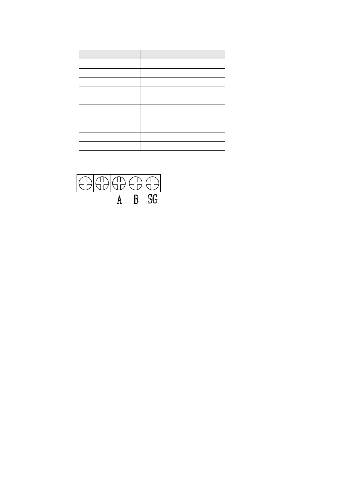
2. RS485:
Num Name Description
1 TX+ 422 send positive signal
2 RX 232 receive signal
3 TX 232 send signal
4 NC (This pin connect to the CPU pin inside OP10. Low
level: The 232 communication port of OP10 is ready
to receive configuration data. High level: no use )
5 GND GND
6 TX- 422 send negative signal
7 RTS (VCC, give power supply to SG2 program cable)
8 RX- 422 receive negative signal
9 RX+ 422 receive positive signal
Num Name Description
1 A 485 positive signal
2 B 485 negative signal
3 SG 485 GND
57
Page 61

5.2 Communication connect
d
(OP10-PCLINK)
5.2.1 OP10 downloading cable ( write configuration screens )
PC side 2 RX 3TX OP10 side
3 TX 2 RX (9-pin D-shape
female plug)
Black 4 Gray
5 GND 5GND
ownload cable
9PIN(
4KA97X033W01
female)
shielded
PC side(black)
shielded
OP10 side(gray)
(9-pin D-shape
female plug)
9PIN(male)
1
6
2
7
3
8
4
9
5
Black
(PC with serial port)
Gray
(If there are no serial ports on PC, we need a USB serial port: 4KA97X017W01)
5
9
4
8
3
7
2
6
1
5.2.2 Connect with TP03 (include SR type) PG port through RS-422
1 TX+ 2RX+
OP10 side 6 TX- 1RX- PLC side
8 RX- 4TX- (9-pin D-shape
female plug)
5GND 3GND
58
9 RX+ 7TX+
(8-pin round male
plug)
Page 62

Idiographic connection: (TP03-102MC cable)
COM
COM
0
1234
5
6
RUN
+24V
STOP
output
0V
IN
1
324657
013
SG
OUT
01 324657
B
A
COM0
COM1
0
123
710 1211
PWR
20SR-A
5
9
4
8
3
7
2
6
1
RUN
1110
12
13
6547
shielded
9PIN(female)
SR-A系列
TP03系列
(TP03-102MC)
TP03-102MC
8PIN(male)
7 8
6
45
3
21
5.2.3 Connect with TP03 through 485 port
0P10
RS-485
A A 1
B
TP03:
TP03 485 port
B 2
59
Page 63

TP03SR:
COM
COM
0
123
+24V
output
0V
IN
SG
OUT
B
A
COM0
5.2.4 Connect with SG2 through 232 port (suitable for all types of SG2)
A2
A1I4 I6I5+-I1 I2 I3
DC 24V Input 8 x DC(A1,A2 0~10V)
5
710 1211
4
6
RUN
PWR
STOP
1
324657
01
01 324657
20SR-A
COM1
123
0
13
RUN
12
1110
3
547
6
Run
SG2-12KR-D
Q1 Q2
SG2-Client
5.2.5 Connect with SG2-V type with 485 port
60
Page 64

5.2.6 Connect with EV300 through 485 port
JNSIF-485
SIF-485
5.2.7 Connect with SV300
black
red
red
black
SIF-485
61
Page 65

62
 Loading...