

Page 1
Product Overview
Power
10 - 48 VDC
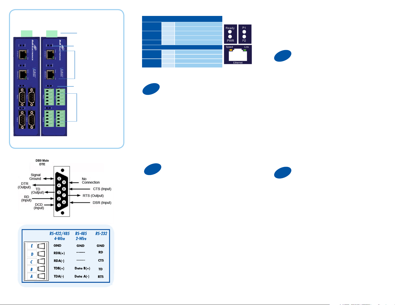
LEDs
Fiber/Ethernet
Ports
LEDs
LEDs
Power
Ready
P (1 - 4)
RJ45 Ethernet Port LEDs
Speed
Link
1
Off Power is not connected
On Power is connected
Off System is in Console Mode
Blink System is in Normal Mode
Blink Data present on serial port
Off 10BaseT connection
On 100BaseTX connection
On Ethernet connected
Blink Data present on Ethernet port
Set Up Hardware
5. Click “Login”. Password is blank from factory.
No password is necessary to operate the MESR
unit. The Configuration/General page appears.
3
“I want DHCP” is preselected to set up the network
using dynamic IP addressing. The Gateway is set
up at the factory to receive an IP assignment from a
DHCP Server.
Set Up Network
Male DB9 Ports or
Terminal Block Ports
1. Power the device.
2. Connect the top RJ45 or optical connector
to a network drop using a standard network
cable. (The RJ45 ports on the model shown are
interchangeable. One may used for pass-through
Ethernet.)
3. Connect the Serial Device(s).
RS-232 with DB9: straight-through for DCE
device. Null modem for DTE device.
RS-422/485 with terminal blocks.
2
1. Use included CD to install Vlinx Modbus Gateway
Manager. If Autorun does not start, go to “My
Computer” and select the CD drive. You will see
a Vlinx MESR icon. Double-click it to launch the
installation.
2. To open Vlinx Modbus Gateway Manager: click
Start\Programs\B&B Electronics\Vlinx\Vlinx Modbus
Gateway Manager.
If the device does not connect, cycle (unplug-replug)
the power, then try again.
3. To configure via the network, select “Network”.
4. If you know the IP address, select “The device is
at this address,” and type in the IP address. If not,
select “I don’t know the IP address of the device.” Click
Connect.
(Alternative Method: Open a web browser and type
the IP address of the Gateway in the Address Bar.
When the Gateway is found the Login window will
appear.)
Install/Setup
1. If a DHCP Server is not available on your network,
it will default to 169.254.102.39.
2. If a DHCP server is not available and the default
address does not work on your PC, change your PC
network settings to IP Address: 169.254.102.1, Subnet
Mask: 255.255.0.0, Default Gateway: 169.254.1.1.
If you are not able to use these settings in your
installation, refer to the User’s Manual for directions to
change the Gateway’s TCP/IP settings.
4
Note: The Vlinx Modbus Gateway Manager
software contains default parameter values that
are common to most Modbus networks.
TCP Settings:
“Connect to port” identifies TCP port used in TCP
client mode. Valid range is 1 to 65535. Default is
502.
Response timeout is the maximum response time.
Valid range is from 1 to 65535. Default is 100ms.
TCP Server Settings:
“Listen on port” identifies TCP port in TCP server
mode. Valid range is from 1 to 65535. Default is
502.
“Limit the number of connections” controls the number
of simultaneous TCP clients that can be connected.
Connection Filter Mode options like “allow everyone,”
“allow specific IP address” and “allow a range of IP
addresses” control which TCP clients can connect.
If You Wish to Set Up TCP
Page 2
Troubleshooting
The primary check for correct operation is the
device LEDs.
For advanced information, see the Configuration
Manager menu, at the top of Vlinx Modbus
Gateway screen.
Select Diagnostic for a check of
communications status with attached MESR424
device, and then select the device for which the
communications check is desired. A report of
reply times and ping statistics is generated and
can be saved.
Select Monitor to review activity logs of
attached MESR424 devices, then select the
device for which logged information is needed.
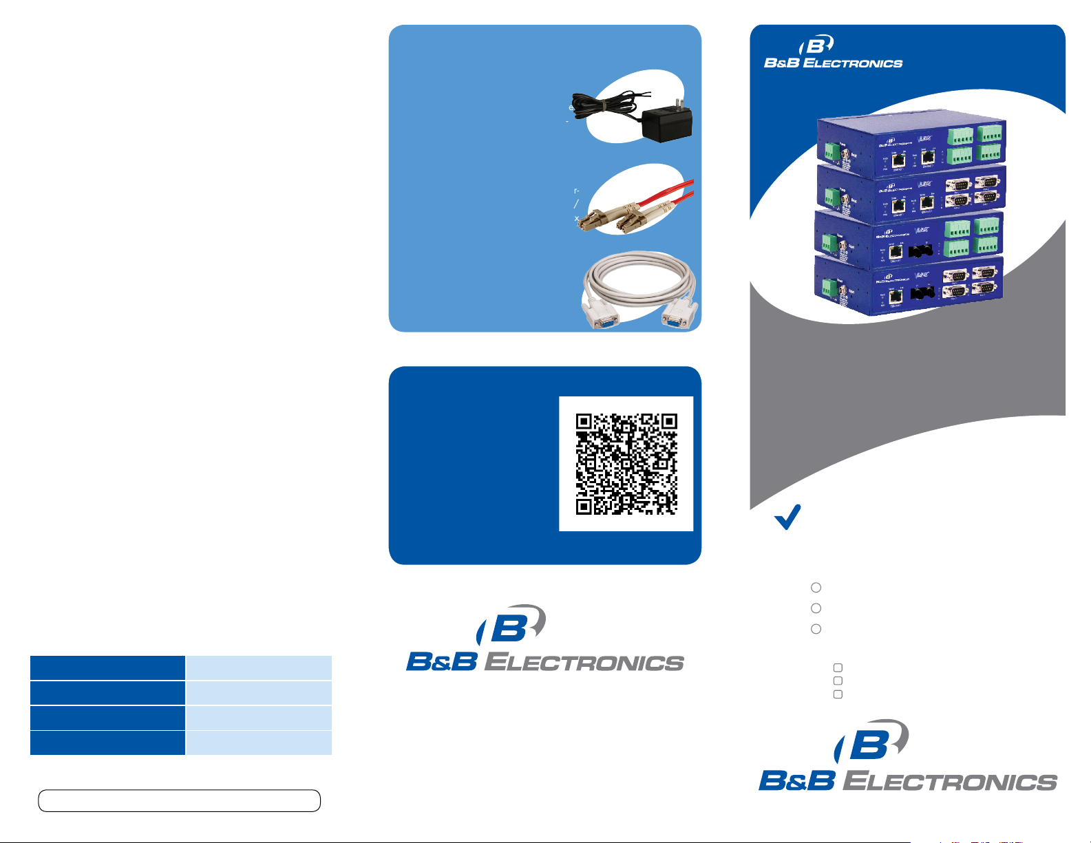
Recommended Accessories
PS12BVLB-INT-MED
Power Supply
http://www.bb-elec.com/Products/Power-
Supplies-Accessories/Wall-Transformer-
Power-Supplies/Power-Supplies.aspx
DFMM-LCLC
Fiber Cable
http://www.bb-elec.com/Products/Power-
Supplies-Accessories/Fiber-Optic-Cables/
Multi-mode-Fiber-Optic-Patch-Cables.aspx
232NM9
Null Modem Crossover Cable for DTE to
DTE connection
http://www.bb-elec.com/Products/PowerSupplies-Accessories/Serial-Cables/NullModem.aspx
MESR424
Q
S
G
uick
tart
uide
Logged information includes Time, Source &
Destination, Type of Event, Subscriber
ID, Data Collected, and Information the
Vlinx Modbus Gateway Manager program has
gathered since current login of the affected
device.
Mode Switch Result
Hold in for 0 - 2 seconds Initiates a Hardware Reset
Hold in for 2 - 10 seconds Enters Console Mode
Hold in for over 10 seconds Reset to factory defaults
Document number – pn9800_R000_MESR424_4312qsg
Fast Easy Answers
You can use your
smart phone to
access complete
documentation
on our website. Simply
scan the code to the
right.
1-888-948-2248 | Europe: +353 91 792444
www.bb-elec.com
707 Dayton Road | PO Box 1040 | Ottawa, IL 61350
Phone: 815-433-5100 | Fax: 815-433-5109
www.bb-elec.com | E-mail: info@bb-elec.com
© 2012 B&B Elect ronics Manufacturing Company
Industrial MODBUS
Ethernet to Serial Gateways
First Things First...
Before you begin, be sure you have
the following:
MESR424
CD with software and manuals
Mounting accessories kit
Additional items required but not included:
Ethernet cable(s)
Null modem cable(s)
Power Supply for terminal block
or barrel connector
Fast and easy on the web:
www.bb-elec.com
Page 3
5
Set Up Serial Port
4th box - auto fills based on ranges entered in the
Recommended Accessories
first three columns.
and Power Supplies
Set up additional ports the same way.
Q
S
G
uick
tart
uide
Note: The Vlinx Modbus Gateway Manager
software contains default parameter values
that are common to most Modbus networks.
1. Change the Description of the serial port if
needed.
2. Set the Mode to RS-232, RS-422 (4-wire),
RS-485 (2-wire) or RS-485 (4-wire).
3. Set the Baud Rate to control the speed of the port.
Valid rates range between 75 and 230.4k bits per
second.
5. Set the Data Bits to control the number of bits
in each character. Only 8 bits is valid when the
protocol of the device connected to the port is RTU.
4. Stop Bits controls the number of bits for end of
character.
5. Parity controls the error checking mode, with
options of No Parity, Odd, Even, Mark and Space.
6
Select the Attached as Master or Slave.
1. Select the Modbus protocol to be used, either RTU
or ASCII.
2. As needed, check option boxes for “Enable
Modbus broadcast, “Enable 0Bh Exception” and
“Enable serial message buffering.”
3. Select from 0 to 5 Modbus Serial Retries.
4. Enter Milliseconds Modbus Message Timeout, from
1 to 65535.
5. Enter Milliseconds TX Delay, from 1 to 65535.
6. Set up additional Modbus ports the same way.
7
Use this screen if Modbus Slave IDs are to be
remapped. On each line select a range of serial ports
to remap.
1st box - enter the first serial port of the range to
remap FROM. Valid port IDs range from 1 to 247.
2nd box - enter the last serial port of the range to
remap.
3rd box - enter starting ID of the range to remap
TO.
Set Up Modbus Port
Set Up Port ID Remap
8
Use this screen if Modbus Slave IDs are to be
rerouted.
On each line select the range of IDs to re-route.
1st box - enter the starting ID. Valid IDs range from
1 to 247.
2nd box – enter the last ID of the range to re-route.
3rd box - enter the IP Address or Port that has slave
devices attached.
4th box - shows the IP address of the slave device,
if an IP address is chosen in the third box.
9
Use this screen if Modbus Priority is to be set.
Enter up to five different priorities, based on
Originating IP Address, Modbus ID, Modbus Function
Code, or a combination of these.
Modbus ID has a valid range from 1 to 247.
Function Code has a valid range from 1 to 99.
10
Th
If you have completed the configuration, click Save to
save the configuration to the serial server. Allow 15
seconds for the Gateway to reboot.
Click “Connect.” You should see a list of all
devices on the network, including your new
device. If you do not see your new device,
please refer to the Troubleshooting tips.
You may now log out.
Information - FCC rules
This device complies with Part 15 of the FCC rules.
Operation is subject to the following two conditions:
(1) This device may not cause harmful interference.
(2) this device must accept any interference that may
cause undesired operation.
Setup Modbus ID Routing
Setup Modbus Priority
Finish and Log Out
MESR424
Industrial MODBUS
Ethernet to Serial Gateways
 Loading...