

Page 1
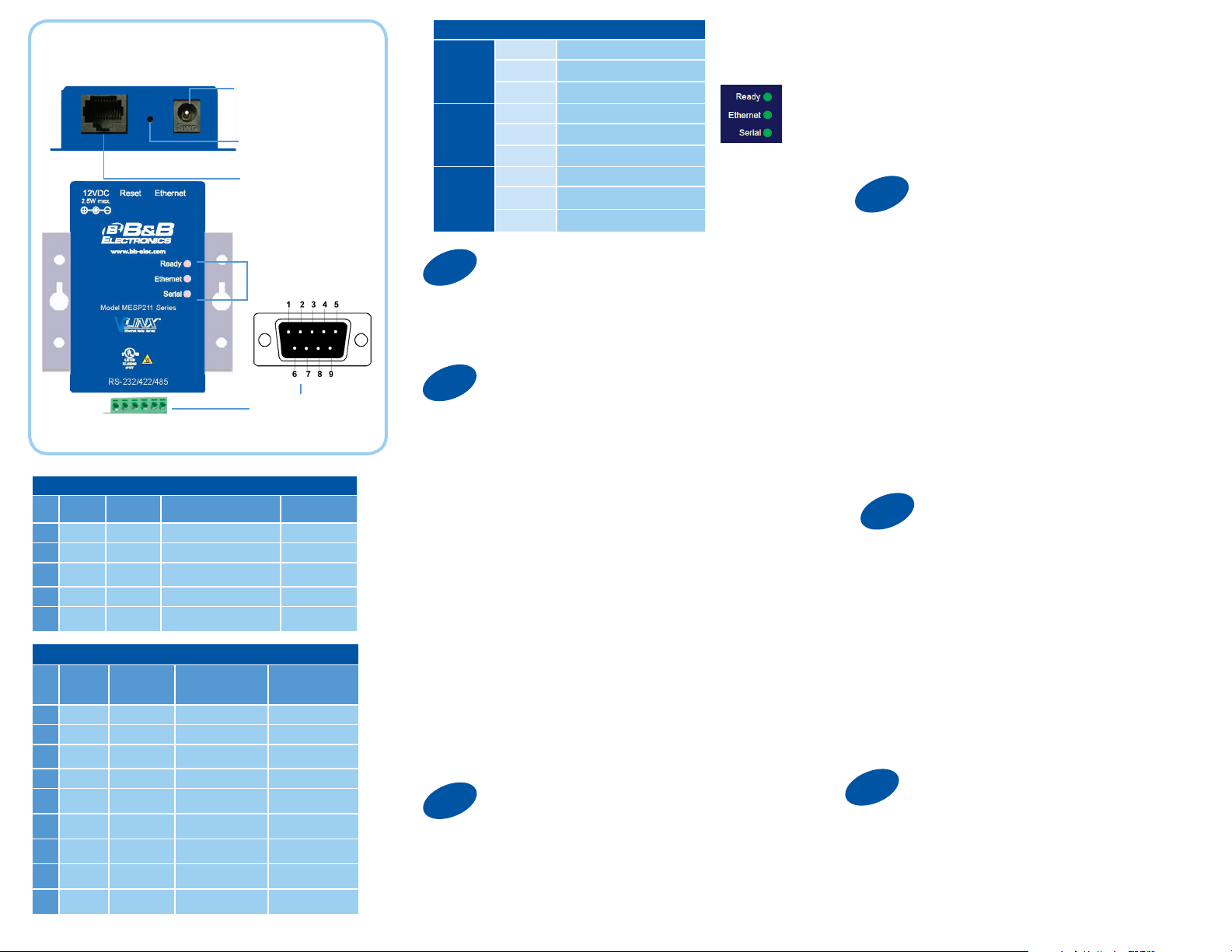
Product Overview
E D C B A
Terminal Block Pinout
Pin RS-232
A RTS
B TD
C CTS
D RD
E GND
DB9 Male Pinout
Pin
1
2
3
4
5
6
7
8
9 ****
Direction
(RS-232)
Output TDA (-) Data A (-)
Output TDB (+) Data B (+)
Input RDA (-) ****
Input RDB (+) ****
**** GND GND
RS-232
DCD
RXD
TXD
DTR
GND **** GND GND
DSR
RTS
CTS
Direction
(RS-232)
Input
Input
Output
Output
Input
Output
Input
**** **** ****
RS-422/RS-485 4W RS-485 2W
RS-422/485
4-Wire
RDA (-) ****
RDB (+) ****
TDB (+) Data B (+)
TDA (-) Data A (-)
**** ****
**** ****
**** ****
Power
10 - 30 VDC
Reset/Mode Switch
Ethernet Port
LEDs
DB9M or
Terminal Block
RS-485
2-Wire
LEDs
Ready
Ethernet
Serial
1
OFF
ON During normal boot up
BLINK
OFF No Network link
ON Network link
BLINK Network Activity
OFF No Serial Port Activity
ON Console Mode
BLINK
Set Up Hardware
Unit not Ready, or Unit is in
Console Mode
Slow Blink - Normal Operation
Fast Blink - Device is Rebooting
Data is being transmitted or
received
1. Connect RJ45 first. DHCP is enabled by default.
2. Power the device.
3. Connect the Serial Device.
2
Install/Setup
1. Use included CD to install Vlinx Modbus Gateway
Manager. If Autorun does not start, go to “My
Computer” and select the CD drive.
-- To start the installation on a 32-bit version of Windows double-click
on: CDROM:\Windows\32-Bit\MESR32.exe.
-- To start the installation on a 64-bit version of Windows doubleclick on: CDROM:\Windows\64-Bit\MESR64.exe.
2. To open Vlinx Modbus Gateway Manager: click Start/Programs/
B&B Electronics/Vlinx/Vlinx Modbus Gateway Manager/Modbus
Gateway Manager.
3. To configure via the network, select “Network”.
4. If you know the IP address, select “The device is
at this address,” and type in the IP address. If not,
select “I don’t know the IP address of the device.” Click
Connect. If the device does not connect, cycle (unplug-replug) the
power, then try again.
(Alternative Method: Open a web browser and type the IP address
of the Modbus Gateway in the Address Bar. When the Modbus
Gateway is found the Login window will appear.)
5. Click “Login”. Password is blank from factory.
No password is necessary.
3
Set Up Network
“I want DHCP” is preselected to set up the network using
dynamic IP addressing. The Gateway is set up at the factory to
receive an IP assignment from a DHCP Server.
1. If a DHCP Server is not available on your network, it will
de f aul t to 16 9. 254.102.39.
2. If a DHCP server is not available and the default address
does not work on your PC, change your PC network settings
to IP Address: 169.254.102.1, Subnet Mask: 255.255.0.0,
Default Gateway: 169.254.102.100.
If you are not able to use these settings in your installation,
refer to the User’s Manual for directions to change the
Gateway’s TCP/IP settings.
4
If You Wish to Set Up TCP
Note: The Vlinx Modbus Gateway Manager
software contains default parameter values that
are common to most Modbus networks.
1. TCP Settings:
“Connect to port” identifies TCP port used in TCP client
mode. Valid range is 1 to 65535. Default is 502. Response
timeout is the maximum response time.
Valid range is from 1 to 65535. Default is 100 ms.
2. TCP Server Settings:
“Listen on port” identifies TCP port in TCP server mode.
Valid range is from 1 to 65535. Default is 502. “Limit the
number of connections” controls the number of simultaneous
TCP clients that can be connected. Connection Filter Mode
options like “allow everyone,” “allow specific IP address”
and “allow a range of IP addresses” control which TCP
clients can connect.
5
Set Up Serial Port
Note: The Vlinx Modbus Gateway Manager
software contains default parameter values
that are common to most Modbus networks.
1. Change the Description of the serial port if
needed.
2. Set the Mode to RS-232, RS-422,
RS-485 (2 wire) or RS-485 (4 wire).
3. Set the Baud Rate to control the speed of the port. Valid
rates range between 75 and 230.4k bits per second.
4. Stop Bits controls the number of bits for end of
character.
5. Parity controls the error checking mode, with
options of No Parity, Odd, Even, Mark and Space.
6
Finish and Log Out
There are additional Modbus configuration pages that may
be accessed by selecting “Next” at the bottom of each
page, or by selecting the desired page from the
vertical list in the left-hand column.
Continued on the next page...
Page 2
Continuing Section 6
The Vlinx Modbus Gateway Manager defaults to options
like “Network” and “I don’t know the IP of the device.” If
the defaults meet your needs you don’t
need to set or change them.
If you have completed the configuration, click Save to
save the configuration to the serial server. Allow 15
seconds for the Gateway to reboot.
Click “Connect.” You should see a list of all devices on
the network, including your new device. If you do not
see your new device, please refer to the Troubleshooting
tips. You may now log out.
Troubleshooting
The primary check for correct operation is the
device LEDs.
For advanced information, see the Configuration Manager
menu, at the top of Vlinx Modbus Gateway screen.
Select Diagnostic for a check of communications
status with attached MESP211 device, and then
select the device for which the communications
check is desired. A report of reply times and ping statistics is
generated and can be saved.
Select Monitor to review activity logs of attached MESP211
devices, then select the device for which logged information
is needed.
Logged information includes Time, Source &
Destination, Type of Event, Subscriber ID, Data
Collected, and Information the Vlinx Modbus
Gateway Manager program has gathered
since current login of the affected device.
Mode Switch Result
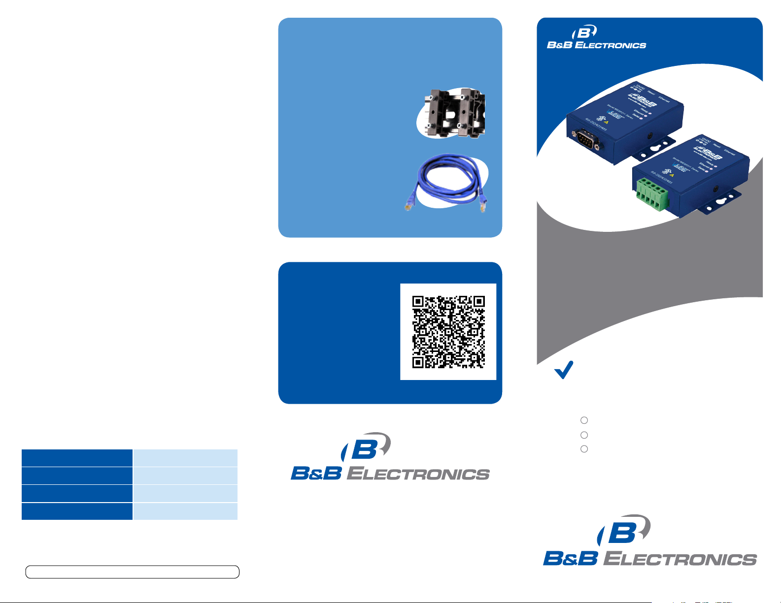
Recommended Accessories
and Power Supplies
DRAD35
DIN Rail Adapter
http://www.bb-elec.com/Products/
Power-Supplies-Accessories/SerialCables/Accessories.aspx
Ethernet Cables
http://www.bb-elec.com/
Products/Power-SuppliesAccessories/Ethernet-Cables.aspx
Fast Easy Answers
You can use your
smart phone to
access complete
documentation
on our website. Simply
scan the code to the
right.
Q
uick
S
tar t
G
uide
MESP211
Ultra Compact MODBUS
Ethernet to Serial Gateways
First Things First...
Before you begin, be sure you have
the following:
M ES P 211
CD with software and manuals
Power supply
Hold in for 0 - 2 seconds Initiates a Hardware Reset
Hold in for 2 - 10 seconds Enters Console Mode
Hold in for over 10 seconds Reset to factory defaults
Document number – pn710-08860-04_R1_MESP211_2713qsg
1-888-948-2248 | Europe: +353 91 792444
www.bb-elec.com
707 Dayton Road | PO Box 1040 | Ottawa, IL 61350
Phone: 815-433-5100 | Fax: 815-433-5109
www.bb-elec.com | E-mail: info@bb-elec.com
© 2012 B& B Electroni cs Manufa cturing Company
Fast and easy on the web:
www.bb-elec.com
 Loading...