


INSTRUCTION MANUAL
M3LDY
CURRENT LOOP SUPPLY
(linearizing; field- and PC-configurable)
BEFORE USE ....
Thank you for choosing M-System. Before use, check the
package you received as below.
If you have any problems or questions with the product,
please contact M-System’s Sales Office or representatives.
■ PACKAGE INCLUDES:
Signal conditioner .......................................................(1)
I/O range and tag name label sheet ........................... (1)
■ MODEL NO.
Check that the model No. described on the specification label
is exactly what you ordered.
■ INSTRUCTION MANUAL
This manual describes the necessary points of caution when
you use this product, including installation, connection and
basic maintenance procedures.
The M3LDY with Option /A is programmable using the PC
configurator software. For detailed information on the PC
configuration, refer to the M3CON instruction manual. The
M3CON PC Configurator Software is downloadable at MSystem’s web site: http://www.m-system.co.jp.
MODEL
■ WIRING
• Do not install cables (power supply, input and output) close
to noise sources (relay drive cable, high frequency line, etc.).
• Do not bind the unit's cables together with cables where
high noise levels are present. Do not install them in the same
duct.
■ AND ....
• The unit is designed to function as soon as power is
supplied, however, a warm up for 10 minutes is required for
satisfying complete performance described in the data sheet.
M3LDY
COMPONENT IDENTIFICATION
Body
Specification Label
(side)
SW Setting Label
POINTS OF CAUTION
■ CONFORMITY WITH UL
(UL is unavailable for certain model suffix options.)
• This equipment is suitable for use in a Pollution Degree 2
environment.
• This equipment is to be used with the maximum operating
voltage 30Vrms and 42.4Vpeak or 60V DC.
• The equipment must be mounted inside a suitable fire
enclosure.
• Operating temperature: -25 to +55°C (-13 to +131°F)
■ POWER INPUT RATING & OPERATIONAL RANGE
• Check the power rating for the unit on the specification
label.
Rating 24V DC: 24V ±10%, approx. 3W
• Power fuse: A power fuse of the rating as shown below is
incorporated for safety. However, DO NOT replace it by the
user.
T 0.25A 125V
■ SAFETY PRECAUTION
• Before you remove the unit or mount it, turn off the power
supply and input signal for safety.
■ ENVIRONMENT
• Indoor use
• When heavy dust or metal particles are present in the air,
install the unit inside proper housing with sufficient ventilation.
• Do not install the unit where it is subjected to continuous
vibration. Do not subject the unit to physical impact.
• Environmental temperature must be within -25 to +65°C
(-13 to +149°F) with relative humidity within 0 to 95% RH in
order to ensure adequate life span and operation.
■ HOW TO OPEN THE COVER WHEN SETTING DIP SW
Hold at the top and bottom of the unit as shown below and
slide the housing cover gently to open until it hits the latching
inside the unit.
Caution:
Handle the cover carefully to protect internal components from damage.
DO NOT pull beyond where the housing cover is latched. The plastic
housing may be damaged.
• Housing Cover Fully Opened
EM-2664 Rev.2P. 1 / 6
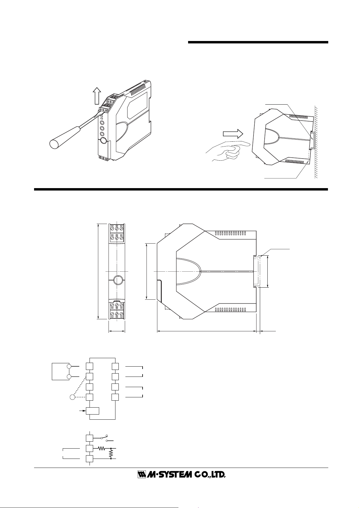
■ HOW TO SEPARATE THE TERMINAL BLOCKS
When you need to separate the terminal blocks from the
transmitter body for wiring, insert a minus driver between
the terminal block and the housing body, pull up the driver
and pull out the terminal block.
TERMINAL CONNECTIONS
Connect the unit by referring to the diagram below.
■ EXTERNAL DIMENSIONS mm (inch)
M3LDY
INSTALLATION
■ DIN RAIL MOUNTING
Set the unit so that its DIN rail adaptor is at the bottom.
Position the upper hook at the rear side of the unit on the DIN
rail and push in the lower. When removing the unit, push
down the DIN rail adaptor utilizing a minus screwdriver and
pull.
DIN Rail
35mm wide
Spring Loaded
DIN Rail Adaptor
■ CONNECTION DIAGRAM
2-WIRE
TRANSMITTER
+
+
–
MONITOR
(1 – 5VDC)
CONFIGURATOR
1
–
2
3
+
4
V
–
JACK
10 11 12
789
106 (4.17)
123
456
18 (.71) 110.5 (4.35)
+
7
–
8
+
11
–
12
62 (2.44)
¥When mounting, no extra space is needed between units.
OUTPUT
POWER
DIN RAIL
35mm wide
35.4 (1.39)
[3.3 (.13)]
■When Used as Isolator
No Connection
INPUT
1
+
2
–
3
250Ω
24.9Ω
EM-2664 Rev.2P. 2 / 6
EXTERNAL & INTERNAL VIEWS
■FRONT VIEW ■SIDE VIEW
10 11 12
789
123
456
LED1 (LD1)
LED2 (LD2)
LED3 (LD3)
MODE Button
UP Button
DOWN Button
Configurator Jack
Configuration DIP SW
4321
87654321
CONFIGURATION MODE & DIP SW SETTINGS
When you program the transmitter module, two configuration modes are available: Field Configuration using DIP SW
/ control buttons, and PC Software. (The Option B type is for
the field configuration only.)
The internal DIP switches are used to configure input and
output type. Once the module is configured, precise ranges
are set up with the front control buttons using a simulator
connected to the input terminals and a multimeter connected
to the output terminals as a reference.
The calibrated input and output ranges are stored in the
internal memory. The module reads the DIP-switch-calibrated configuration only once after the power supply is
turned on. Set the switches with the power supply removed.
Selectable I/O type and ranges are listed in Table 5 and 6.
■ DIP SW CONFIGURATION MODE
Turn the SW2-8 OFF to enable the DIP SW (Field Configuration) mode as shown in Table 1.
See Table 2 to configure the input and Table 3 for the output.
■ PC CONFIGURATION MODE
Turn the SW2-8 ON to enable the PC Configuration mode as
shown in Table 1. All programmable features can be set up
on a PC regardless of other DIP SW setting except that the
output type must be selected with the DIP SW1-1 through
SW1-4 (See Table 4).
For detailed information on the PC configuration, refer to the
M3CON instruction manual.
M3LDY
OFF
ON
OFF
ON
ONOFF
■CONFIGURATION MODE (SW2) Table 1
MODE SW2-8
DIP SW OFF
PC ON
■INPUT TYPE (SW2 & 3) Table 2
INPUT TYPE SW2-7 SW3
DC current
(isolator use)
2-wire loop
(
DC supply use
■OUTPUT TYPE (SW2 & 1) Table 3
OUTPUT SW2-4 SW2-3 SW1-4 SW1-3 SW1-2 SW1-1
0 – 20mA OFF OFF OFF ON OFF OFF
-2.5 – +2.5V OFF ON ON OFF OFF ON
-10 – +10V ON OFF ON OFF ON OFF
■OUTPUT TYPE / PC CONFIG (SW1) Table 4
OUTPUT SW1-4 SW1-3 SW1-2 SW1-1
0 – 20mA OFF ON OFF OFF
-2.5 – +2.5V ON OFF OFF ON
-10 – +10V ON OFF ON OFF
SW1
SW2
SW3
Configuration mode can be
confirmed with the front LED.
ON OFF
)
OFF ON
■ INPUT TYPE & RANGE Table 5
INPUT TYPE MINIMUM SPAN MAXIMUM RANGE
DC Current 2mA 0 to 20mA
■ OUTPUT TYPE & RANGE Table 6
OUTPUT TYPE MINIMUM SPAN MAXIMUM RANGE CONFORMANCE RANGE
DC Current 1mA 0 to 20mA 0 to 24mA
DC Voltage, Narrow Spans 250mV -2.5 to +2.5V -3 to +3V
DC Voltage, Wide Spans 1V -10 to +10V -11.5 to +11.5V
EM-2664 Rev.2P. 3 / 6
M3LDY
CHECKING
1) Terminal wiring: Check that all cables are correctly connected according to the connection diagram.
2) DIP SW setting: Check that the switches are set to appropriate positions.
3) Power input voltage: Check voltage across the terminal 11 – 12 with a multimeter.
4) Input: Check that the input signal is within 0 – 100% of full-scale.
5) Output: Check that the load resistance meets the described specifications.
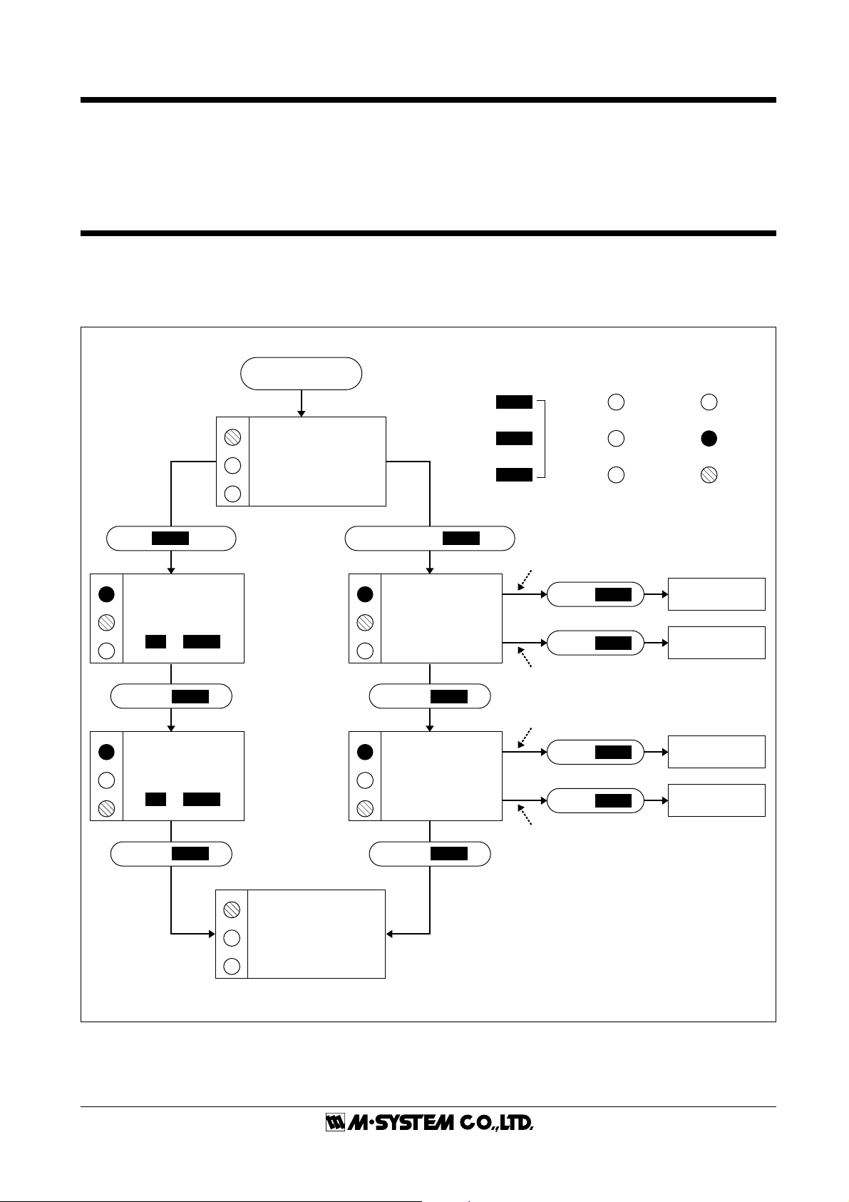
I/O RANGING & FINE ADJUSTMENTS
After the DIP SW setting is complete, set up the precise input and output range using the front control buttons.
The front LEDs’ colors and flashing patterns help you to easily identify the transmitter’s status and confirm the setup actions
in each step of Calibration Modes. Please read the following explanations referring to “Calibration Flow Chart” below.
■ CALIBRATION FLOW CHART
POWER ON
LD1
G
Fine Adjustments ? I/O Ranging ?
LD2
LD3
RUN MODE
G
MODE
PUSH
LD1
R
LD2
CALIBRATION MODE
G R
LD3
PUSH
LD1
R
LD2
CALIBRATION MODE
LD3
G
PUSH
1 – 2 s PRESS & HOLD
1
*
FINE ZERO
UP
or
DOWN
MODE
1
*
FINE SPAN
UP
or
DOWN
MODE
LD1
LD1
R
LD2
LD3
LD1
R
LD2
LD3
R
CALIBRATION
PUSH
CALIBRATION
PUSH
MODE
INPUT
MODE
MODE
OUTPUT
MODE
MODE
G
LD2
LD3
RUN MODE
MODE
Control
UP
Buttons
DOWN
> 5s
Apply simulated 0% input signal.
PUSH
PUSH
Apply simulated 100% input signal.
Adjust simulated input until the output meter
shows desired 0% output.
PUSH
PUSH
Adjust simulated input until the output meter
shows desired 100% output.
When you set 0% or 100% input/output ranges,
keep pressing UP or DOWN button until the
LD1 flashes for approx. 2 seconds and turns off,
which indicates the setup is complete.
When you release the button, the LD1 is returned
to ON.
If the LED does not change, the entered level may
be inappropriate, i.e. out of usable range.
A
G
R
DOWN
UP
DOWN
UP
Amber LED
Green LED
Red LED
OFF
ON
Blink
0% INPUT
CONFIGURED
100% INPUT
CONFIGURED
0% OUTPUT
CONFIGURED
100% OUTPUT
CONFIGURED
*1. Fine zero and calibrations are performed for 0% and 100% output regardless of the input value.
EM-2664 Rev.2P. 4 / 6
M3LDY
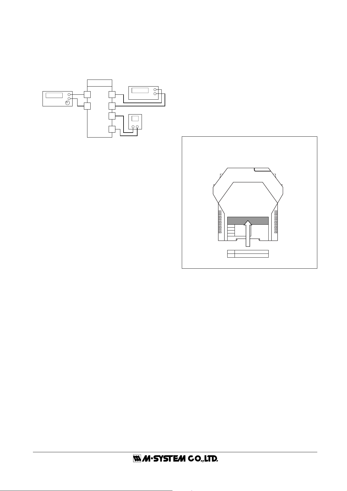
■ PREPARATION (e.g. M3LDY-R/A)
1) Mount the DIP-SW-configured M3LDY on to a DIN rail.
2) Connect the M3LDY to a simulator and a multimeter and
to a DC power source as shown to the right.
3) Turn the power supply on and wait for 10 minutes.
Simulator
M3LDY
+
–
2
3
7
8
11
12
Multimeter
+
–
DC Power Source
+–
■ INPUT & OUTPUT RANGING
[Example]
Setting input to 4 – 20mA DC and output to 1 – 5V DC
1) Run Mode: Confirm that the LD1 green light is blinking.
2) Input Configuration Mode: Press MODE button for longer
than 5 seconds until the LD1 red light is ON and the LD2
red light is blinking.
3) 0% Input Ranging: Apply the desired minimum input
level (e.g. 4mA) from the simulator and push DOWN
button until the LD1 flashes for approx. 2 sec. and then
turns OFF. When you release the button, the LD1 is
returned to ON.
The flashing LD1 means that the value is stored in the
memory. If the LED does not change, the entered level
may be inappropriate: too small a span, or out of usable
range (same for all steps).
4) 100% Input Ranging: Apply the desired maximum input
level (e.g. 20mA) from the simulator and push UP button
until the LD1 flashes for approx. 2 sec. and then turns
OFF. When you release the button, the LD1 is returned to
ON.
5) Output Configuration Mode: Push MODE button and
confirm that the LD3 red light instead of LD2 is blinking.
6) 0% Output Ranging: Increase or decrease the simulated
input until the meter shows the desired minimum output
level (e.g. 1V). Push DOWN button until the LD1 flashes
for approx. 2 sec. and then turns OFF. When you release
the button, the LD1 is returned to ON.
7) 100% Output Ranging: Increase or decrease the simulated
input until the meter shows the desired maximum output
level (e.g. 5V). Push UP button until the LD1 flashes for
approx. 2 sec. and then turns OFF. When you release the
button, the LD1 is returned to ON.
8) Run Mode: Programming complete, push MODE button
and confirm that only the LD1 green light is blinking.
4) Fine Span Calibration Mode: Push MODE button and
confirm that the LD3 green light instead of LD2 is blinking.
5) Use UP (increase) and DOWN (decrease) buttons to adjust
the output to 100%.
6) Run Mode: Push MODE button and confirm that only the
LD1 green light is blinking.
Note 1: Calibration steps can be skipped when not needed by
repeating pushing MODE buttons.
Note 2: There is no stated order of setting 0% and 100% levels
or no limitation of entering values for multiple times within
one step of Calibration Mode. Signal level is stored each time
the respective UP or DOWN button is pressed.
■ I/O RANGE LABEL
Blank I/O range labels are included in the product package. Write in the configured ranges and put the label on
the side above the specification label as shown below.
INPUT
OUTPUT
I/O Range Label (included in the product package)
■ ZERO & SPAN ADJUSTMENTS
After the transmitter is installed and operational, fine zero
and span tuning can be performed as explained below. Both
zero and span are adjustable within ±15%.
1) Run Mode: Confirm that the LD1 green light is blinking.
2) Fine Zero Calibration Mode: Press MODE button for 1 or
2 seconds until the LD1 red light is ON and the LD2 green
light is blinking.
3) Use UP (increase) and DOWN (decrease) buttons to adjust
the output to 0%.
EM-2664 Rev.2P. 5 / 6
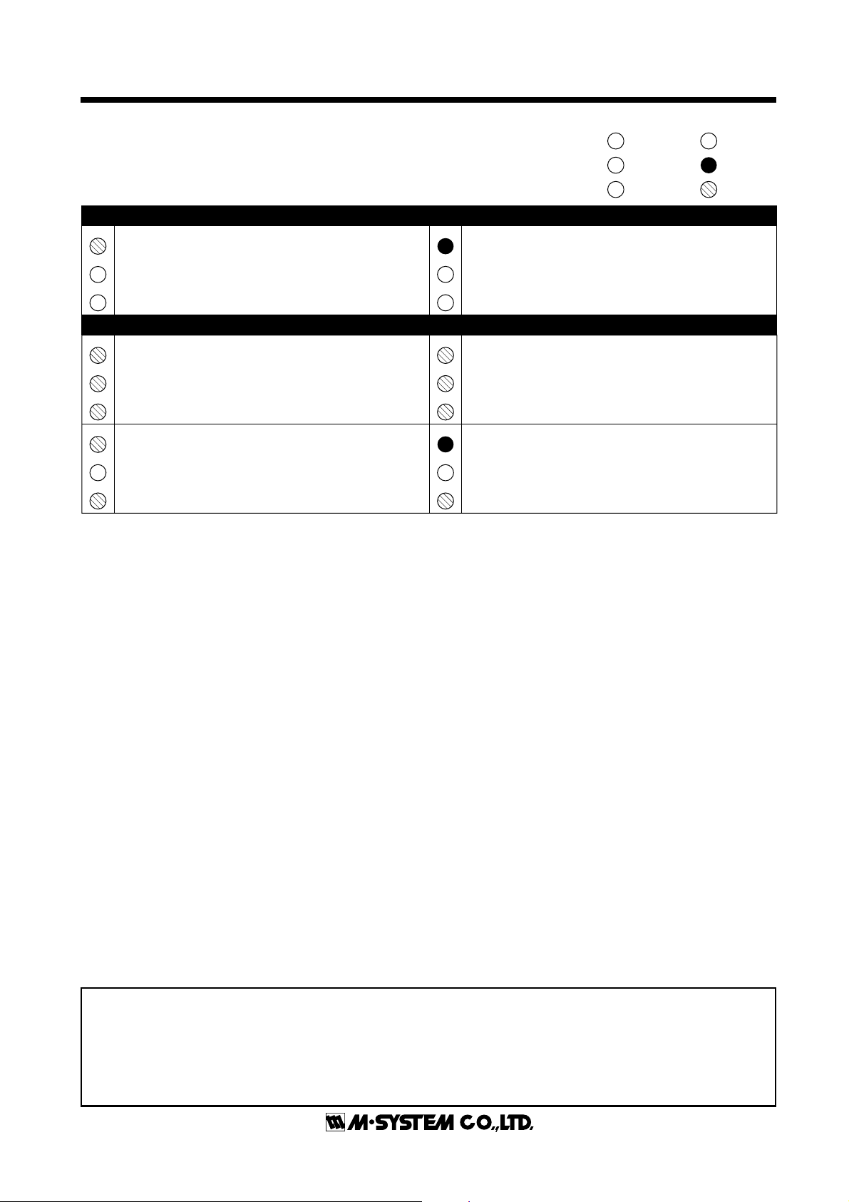
STATUS INDICATOR LED
Combinations of the three front LEDs (LD1, LD2, LD3)
indicate the transmitter’s operating status by different flashing patterns.
Examples are shown below.
NORMAL OPERATION (RUN) MODE
LD1
PC Configuration RUN Mode (Option A)
G
The transmitter is configured via PC and
LD2
is in normal operating conditions.
LD3
ERROR MODE
LD1
System Error
A
Indicates the CPU’s communication error.
LD2
A
LD3
A
LD1
Output Saturated in PC Configuration Mode
G
(Option A)
LD2
The output is saturated.
(approximately below -15% or above +115%)
LD3
A
Amber LED
A
Green LED
G
Red LED
R
LD1
DIP SW Configuration RUN Mode
G
The transmitter is configured via DIP SW and
LD2
is in normal operating conditions.
LD3
LD1
DIP SW Error
R
DIP SW configuration is inappropriate.
LD2
Check the DIP SW setting referring to Tables 2 – 11.
R
LD3
R
LD1
Output Saturated in DIP SW Configuration Mode
G
The output is saturated.
LD2
(approximately below -15% or above +115%)
LD3
A
M3LDY
OFF
ON
Blink
M-SYSTEM WARRANTY
M-System warrants such new M-System product which it manufactures to be free from defects in materials and workmanship during the 36-month period following the date that such
product was originally purchased if such product has been used under normal operating conditions and properly maintained, M-System's sole liability, and purchaser's exclusive remedies,
under this warranty are, at M-System's option, the repair, replacement or refund of the purchase price of any M-System product which is defective under the terms of this warranty. To
submit a claim under this warranty, the purchaser must return, at its expense, the defective M-System product to the below address together with a copy of its original sales invoice.
THIS IS THE ONLY WARRANTY APPLICABLE TO M-SYSTEM PRODUCT AND IS IN LIEU OF ALL OTHER WARRANTIES, EXPRESS OR IMPLIED, INCLUDING ANY IMPLIED
WARRANTIES OF MERCHANTABILITY OR FITNESS FOR A PARTICULAR PURPOSE. M-SYSTEM SHALL HAVE NO LIABILITY FOR CONSEQUENTIAL, INCIDENTAL OR
SPECIAL DAMAGES OF ANY KIND WHATSOEVER.
M-System Co., Ltd., 5-2-55, Minamitsumori, Nishinari-ku, Osaka 557-0063 JAPAN, Phone: (06) 6659-8201, Fax: (06) 6659-8510, E-mail: info@m-system.co.jp
EM-2664 Rev.2P. 6 / 6
 Loading...