

Page 1
Manual Documentation Number M3640D1598 Cover Page
B&B Electronics -- PO Box 1040 -- Ottawa, IL 61350
PH (815) 433-5100 -- FAX (815) 433-5104
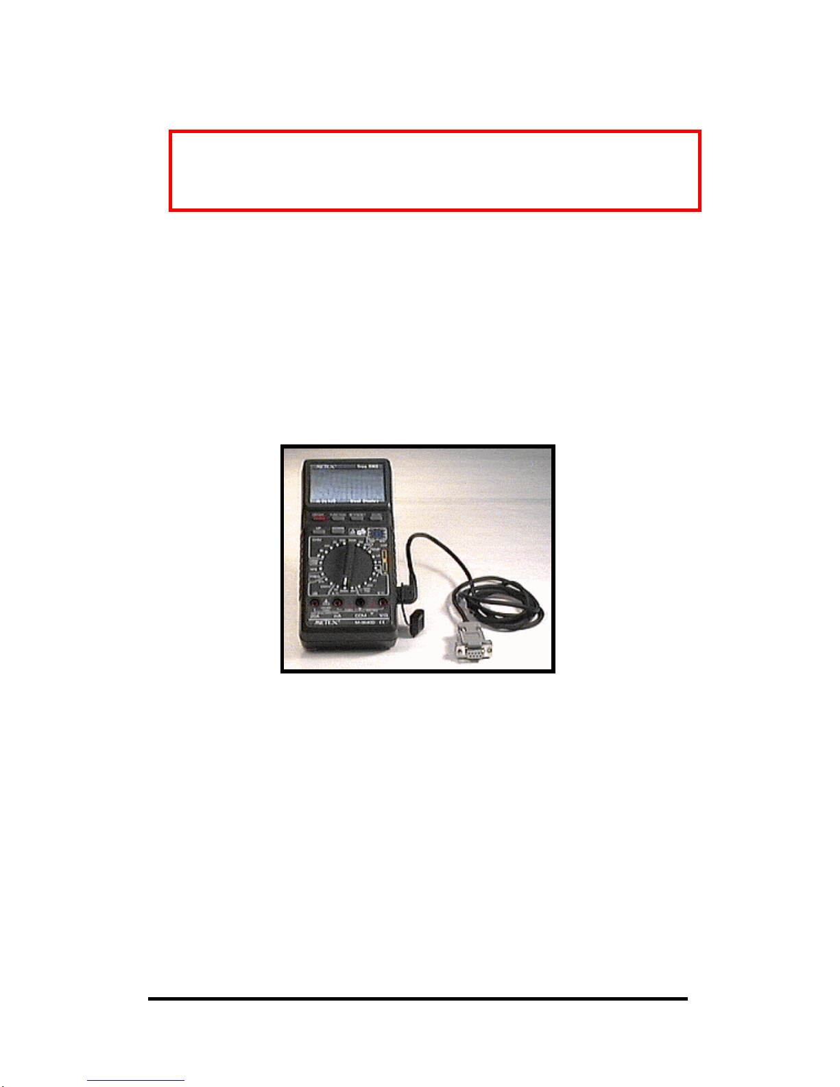
True RMS Handheld Multimeter
Model M-3640D
Documentation Number M3640D1598
B&B Electronics Mfg. Co. Inc.
707 Dayton Road -- P.O. Box 1040 -- Ottawa, IL 61350
PH (815) 433-5100 -- FAX (815) 433-5104
Internet:
http://www.bb-elec.com
sales@bb-elec.com
support@bb-elec.com
B&B Electronics -- May 1997
Not Recommended for New Installations.
Please contact Technical Support for more information.
Page 2

Addendum Manual Documentation Number M3640D1598
B&B Electronics -- PO Box 1040 -- Ottawa, IL 61350
PH (815) 433-5100 -- FAX (815) 433-5104
ATTENTION: METEX USERS
This addendum contains corrections and additions to the user's manual.
Paragraph 6-12-2, page 32, of the M-3640D Digital Multimeter manual
refers to two computer programs: METEX and Scopeview. These
programs are no longer available and have been replaced by METVIEW.
This program works with Windows 3.11, Windows 95, and Windows NT.
Please use the following Installation information and NOT the information
in the manual. The Hardware Interfacing information in paragraph 6-12-1
is correct.
Installing the Supplied Software
We have included a Windows 95/NT program, named METVIEW.EXE, to
log data collected with your meter. To install the software on your hard
drive:
1. Insert the disk in drive A.
2. Click the start button in the lower left corned of the screen and choose
"Settings I Control Panel I Add / Remove Programs".
3. Click the install button and follow the directions.
Using the Software
To run the software after it has been installed, click the start button in the
lower left corner of the screen and choose "Programs I Metex I Metex".
After starting the metex program, click the setup button. A dialog box
appears that allows you to select the serial communications port, sampling
interval, and logging file. Note that the logging file can only be changed
when the “Enabled Data Logging" check box is checked. The filename
may be typed in or you can click the browse button to select where the file
should be located. Once you have completed the setup, click the OK
button.
To start collecting data from the meter, click the button labeled "start".
Data is read from the meter at the sampling interval that was selected when
you setup the software. If data logging is enabled, the data is written to a
disk file. To stop collecting data, click the button labeled "stop". Note that
this is the same button as the start button.
Page 3

Manual Documentation Number M3640D1598 Addendum
B&B Electronics -- PO Box 1040 -- Ottawa, IL 61350
PH (815) 433-5100 -- FAX (815) 433-5104
Format of the Data File
The data is written to the logging file as fixed length records. The format
is:
HH:MM:SS XX######YYYY↵
where HH:MM:SS is the hour (24 hour format), minute and second when
the sample was taken, XX is the meter function, ###### is the value read
from the meter, and YYYY is the units. This file can be read by a program,
such as Microsoft Excel, to analyze the data or print out a chart.
Telephone........................................815-433-5100
8 am--4:30 pm Central Standard Time
Monday through Friday
24-hour FAX...................................815-433-5104
Intemet E-Mail
Sales..................................orders@bb-elec.com
Technical Support.............support@bb-elec.com
World-Wide Web Site .....http://www.bb-elec.com
Postal Mail .....................................B&B ELECTRONICS MFG CO INC
707 DAYTON ROAD
PO BOX 1040
OTTAWA IL 61350 USA
Page 4

Table of Contents Manual Documentation Number M3640D1598
B&B Electronics -- PO Box 1040 -- Ottawa, IL 61350
PH (815) 433-5100 -- FAX (815) 433-5104
Table of Contents
1. INTRODUCTION ..................................................................................1
2. SAFETY INFORMATION ....................................................................2
2-1. Safety Requirements........................................................................2
2-2. Safety Symbols................................................................................2
2-3. Safety Warnings ..............................................................................3
3. PREPARING FOR OPERATION..........................................................4
3-1. Installing the Battery .......................................................................4
3-2. Using the Test Probes......................................................................5
3-3. Using the Stand................................................................................5
4. PRE-OPERATION CHECK...................................................................6
5. HOW TO USE THE METER.................................................................7
5-1. Pushbuttons......................................................................................7
5-2. Items 7-8 describe the Sockets. .......................................................8
5-3. Input Terminals..............................................................................10
5-4. Digital and Bar Graph Displays.....................................................10
5-5. Annunciators..................................................................................14
6. HOW TO MAKE MEASUREMENTS................................................17
6-1 . Measuring DC /AC Voltage.........................................................17
6-2. Measuring Current.........................................................................18
6-3. Continuity Testing.........................................................................19
6-4. Measuring Resistance....................................................................20
6-5 Checking Diode..............................................................................21
6-6. Measuring Frequency....................................................................22
6-7. Measuring Capacitance..................................................................23
6-8. dB Measurement (M-3640D/3660D only)....................................23
6-9. Checking Transistors.....................................................................24
6-10. Measuring Temperature (M-3640D / 3660D only).....................25
6-11. Logic Test....................................................................................26
6-12. Using the Meter with a Computer ...............................................27
7. CARE AND MAINTENANCE............................................................30
7-1. Replacing the Fuse.........................................................................30
7-2. General Maintenance.....................................................................31
8. SPECIFICATIONS...............................................................................32
8-1. General Characteristics..................................................................32
8-2. Special Characteristics...................................................................36
Due to our policy to refine the products continuously, this manual may
contain minor differences in specifications, components, parts and circuit
design from the instrument actually delivered.
Page 5
Manual Documentation Number M3640D1598 1
B&B Electronics -- PO Box 1040 -- Ottawa, IL 61350
PH (815) 433-5100 -- FAX (815) 433-5104
1. INTRODUCTION
The new concept M-3600D Series Multimeters have Dual-Display and
Communication function with computer by RS-232C as basic. The meter is
a handheld 1999 count instrument with True Rms, dB range, temperature
measurement for some models (M-3640D, M-3660D), and frequency
measurement up to 20MHz (M-3650D, M-3660D)
Please read these operating instructions very carefully before commencing
your measurement.
Page 6
2 Manual Documentation Number M3640D1598
B&B Electronics -- PO Box 1040 -- Ottawa, IL 61350
PH (815) 433-5100 -- FAX (815) 433-5104
2. SAFETY INFORMATION
2-1. Safety Requirements
This meter has been manufactured and tested in accordance with IEC 348
and DIN57411/VDE0411 Part 1: Safety Requirement for Electronic
Measuring Apparatus, Safety Class II.
This manual contains information and warnings which must be observed to
assure safe operation and maintain the meter in safe condition.
NOT FOR HIGH ENERGY INDUSTRIAL USE.
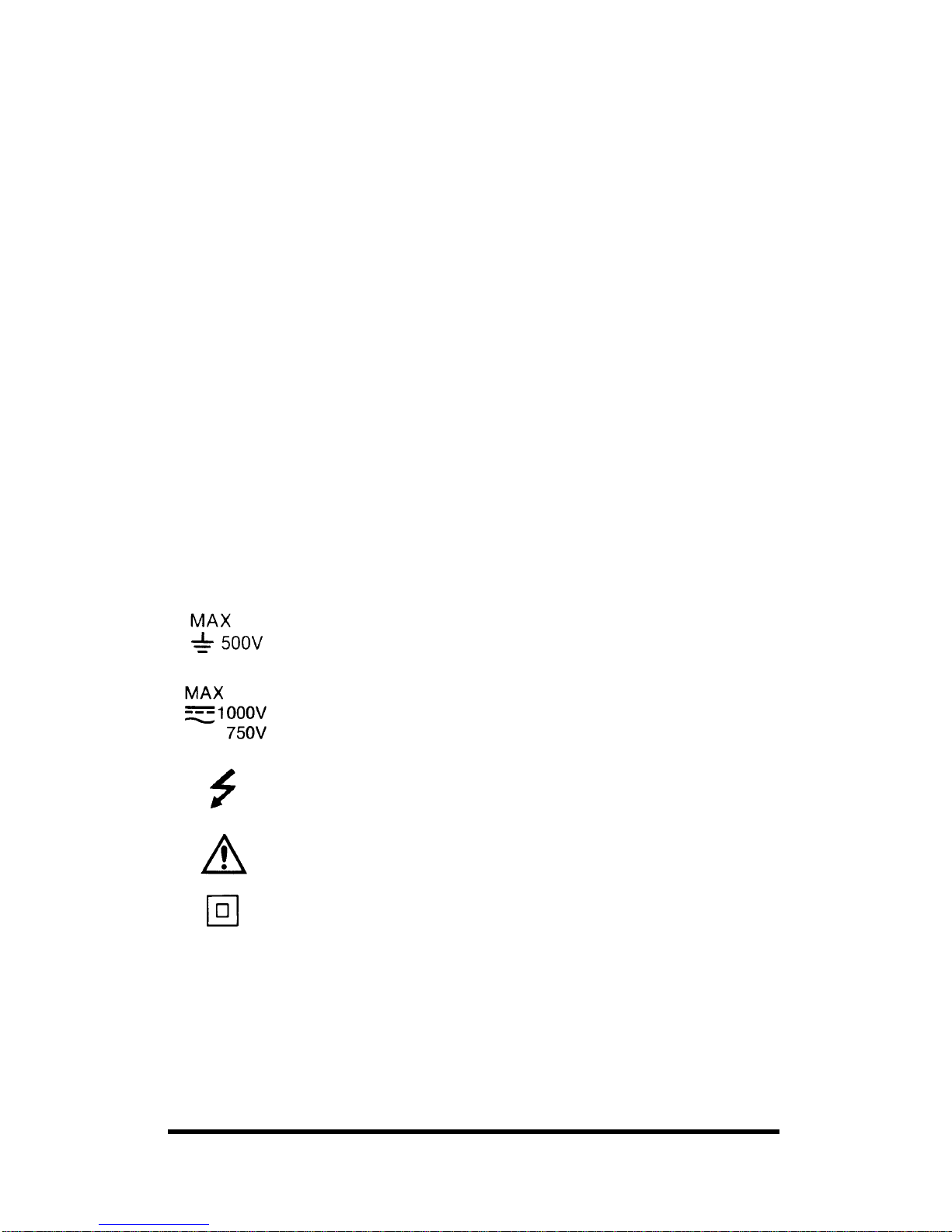
2-2. Safety Symbols
We have placed the following special markings on the panel to remind you
of the measurement limitations and safety.
20A The maximum current that you can measure at this
terminal is 20 amps DC/AC. This terminal is fuse
protected. For your safety during continuous
measurements, keep the duty cycle within 30 seconds in
use and more than 15 minutes in rest.
mA The maximum current that you can measure at this
terminal is 200mA DC/AC. This terminal is fuse
protected.
To avoid electrical shock or instrument damage, do not
connect the Common Input Terminal COM to any source
of more than 500 Volts with respect to earth/ground.
The maximum voltage this meter can measure is 1000V
DC or 750V AC.
Be extra careful when making high-voltage measurements.
DO NOT TOUCH THE TERMINALS OR PROBE
ENDS.
Refer to the complete operating instructions.
Indicates protection class II, double insulation.
Page 7
Manual Documentation Number M3640D1598 3
B&B Electronics -- PO Box 1040 -- Ottawa, IL 61350
PH (815) 433-5100 -- FAX (815) 433-5104
2-3. Safety Warnings
2-3-1. To prevent electric shock hazard and/or damage to the meter,
do not measure voltage exceeding 1000V DC or 750V AC.
2-3-2. To avoid damage to the meter and/or injury, observe the input
limits as stated in Table 1.
2-3-3. To avoid damage to the meter, disconnect test leads from test
points before changing the function/range.
2-3-4. To avoid electric shock, use caution when working above 60V
DC or 25V AC RMS. Such voltage pose a shock hazard.
2-3-5. The 20A range is protected by the fuse. To avoid damage or
injury, use the meter only in circuits limits by fuse or
circuit-breaker to 20A or 4000VA.
Do not apply voltage to between 20A or mA and COM
terminals. This warning is to assure protection against injury
and/or damage to the meter and the user.
2-3-6. Do not get the meter and test leads wet.
2-3-7. Ensure the test leads are in good condition.
Table 1. INPUT LIMITS
FUNCTION TERMINAL INPUT LIMITS
V DC
V/Ω+COM
1000V DC
V AC
V/Ω+COM
750V AC
Ω V/Ω+COM
250V DC/AC
mA DC/AC mA+COM 200mA DC/AC
20A DC/AC 20A+COM 20A DC/AC
V/Ω+COM
250V DC/AC
Freq.
V/Ω+COM
750V DC/AC
Logic
V/Ω+COM
250V DC/AC
DB
V/Ω+COM
20V AC
Page 8
4 Manual Documentation Number M3640D1598
B&B Electronics -- PO Box 1040 -- Ottawa, IL 61350
PH (815) 433-5100 -- FAX (815) 433-5104
3. PREPARING FOR OPERATION
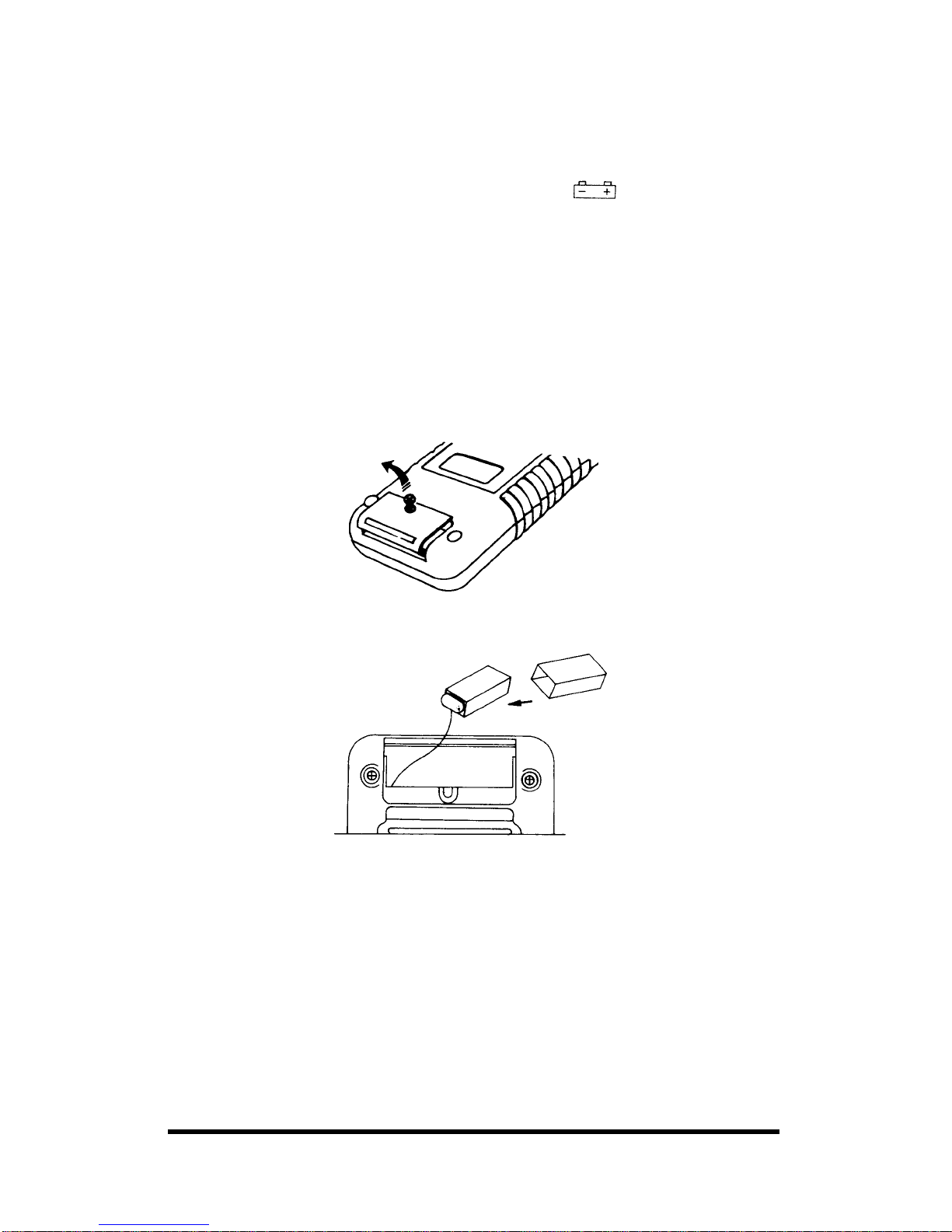
3-1. Installing the Battery
Your meter requires a 9V battery for power. The symbol appears
when the battery voltage drops to certain limits. For proper operation,
replace the battery as soon as possible. Continued use with a low battery
will lead to abnormal readings.
WARNING: TO AVOID ELECTRIC SHOCK, DISCONNECT BOTH
LEADS FROM EQUIPMENT BEFORE YOU REMOVE OR INSTALL
THE BATTERY.
Follow these steps to install the battery:
1. Turn off the power and disconnect the two test probes.
2. Remove the screw to open the battery compartment.
3. Place the battery into the insulation capsule and snap it on the
contacts.
WARNING: DO NOT DISCARD THE PROVIDED BATTERY
INSULATION CAPSULE. IF YOU DO NOT USE THIS
INSULATION CAPSULE PROPERLY, IT MIGHT CAUSE
DAMAGE OR INJURY.
4. Replace the battery compartment cover and secure it with the screw.
WARNING: DO NOT OPERATE THE METER UNTIL YOU
REPLACE THE BATTERY AND CLOSE THE BATTERY
COMPARTMENT COVER.
Page 9
Manual Documentation Number M3640D1598 5
B&B Electronics -- PO Box 1040 -- Ottawa, IL 61350
PH (815) 433-5100 -- FAX (815) 433-5104
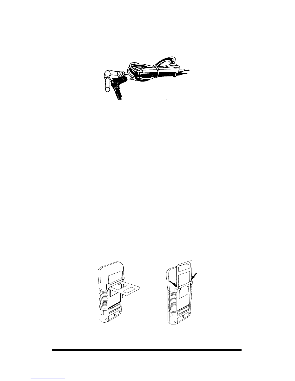
3-2. Using the Test Probes
Use only the type of test probes supplied with your meter. These test
probes are rated for 1200 volts.
Cautions:
• Although the replacement test probes are rated for 1200 volts, the
maximum rating of your meter is 1000 volts DC and 750 volts AC.
If you try to measure DC voltages above 1000 volts or AC
voltages above 750 volts rms, you might damage your meter and
expose yourself to a serious shock hazard. Use extreme care
when you measure high voltages.
• Never connect the probe you plug into the COM terminal to a
source of voltage greater than 500 volts with respect to earth
ground. This creates a serious shock hazard.
3-3. Using the Stand
Use your meter’s stand to prop up or hang the meter.
Propping Up the Meter
If you prop your meter on a benchtop, the stand helps provide a better
viewing angle. To use the stand as a prop, just open it away from the meter
and set it on a flat surface.
Hanging the Meter
To hang the meter, remove the stand by pressing the lower parts of the
stand together. Then insert the stand into top 2 holes.
Page 10
6 Manual Documentation Number M3640D1598
B&B Electronics -- PO Box 1040 -- Ottawa, IL 61350
PH (815) 433-5100 -- FAX (815) 433-5104
4. PRE-OPERATION CHECK
To ensure correct operation and familiarize yourself with the meter, follow
these steps before you use it.
4-1. Press the ON/OFF button to ON
4.2 To select a function, turn the rotary switch to the appropriate switch
position at your desire. The meter is ready for normal operation.
4.3 To select an additional operation, press the appropriate push buttons
above the rotary (See Table 2)
• To operate the UP DOWN buttons, press to address the stored
reference value in the
; modes, press to determine the
polarity, reference value in the
and modes.
• To operate the FUNCTION button, press to select the function mode
at your desire, press again to scroll and press SET/RESET button
twice to exit.
• To operate the SET/RESET button, press to enter, and press again to
exit.
• To operate the DC/AC button, press to toggle between AC and DC
when the rotary switch set to Voltage or Current.
Page 11
Manual Documentation Number M3640D1598 7
B&B Electronics -- PO Box 1040 -- Ottawa, IL 61350
PH (815) 433-5100 -- FAX (815) 433-5104
5. HOW TO USE THE METER
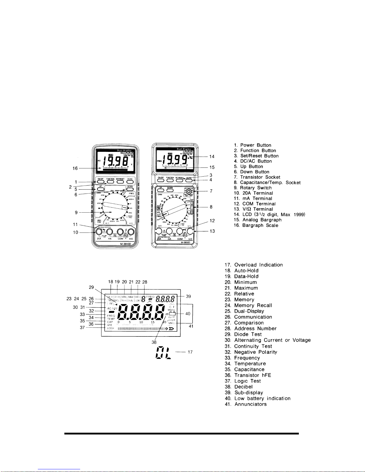
This section describes your meter and how to use it. FOR EASE OF
REFERENCE, EACH DESCRIPTION IS NUMBERED AND KEYED
TO THE ILLUSTRATION INSIDE THE FRONT COVER.
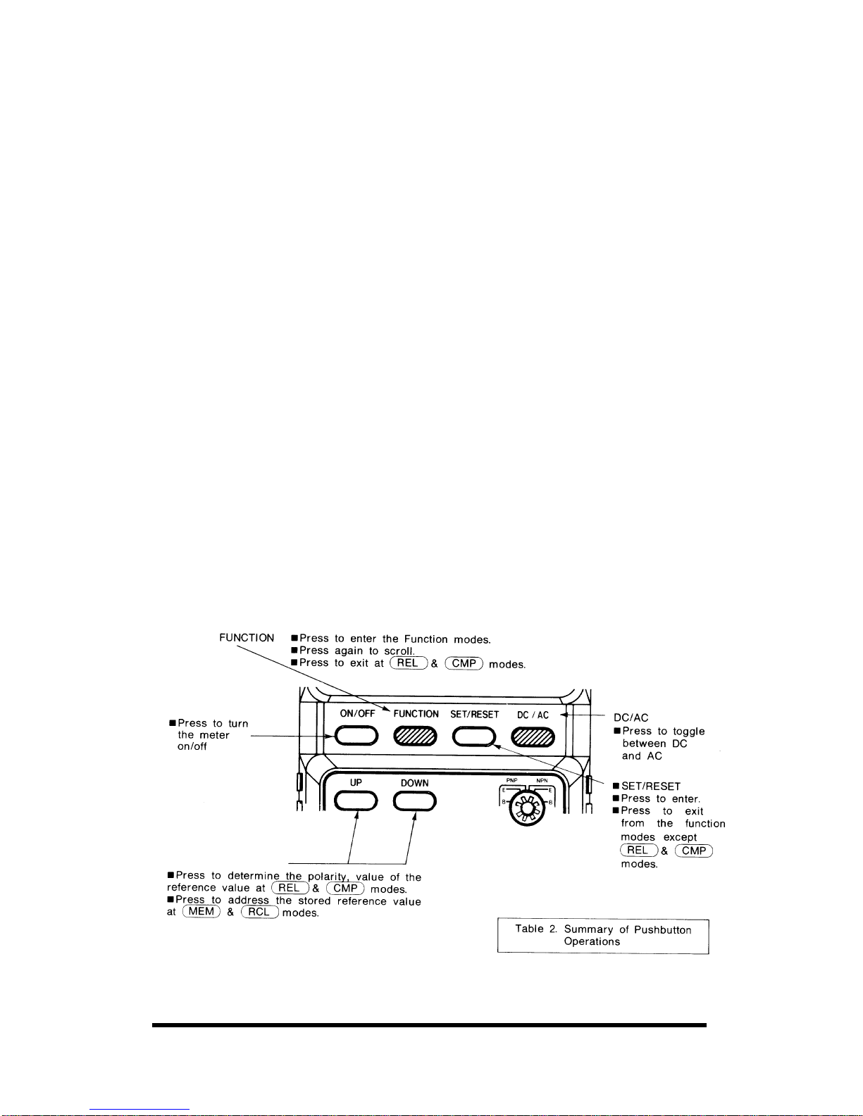
5-1. Pushbuttons
Items 1-6 describe how to use the pushbuttons. These buttons are used (in
conjunction with rotary switch) to select operating modes. When a button
is pushed the beeper sounds. A summary of pushbutton operation is shown
in Table 2. An annunciator is displayed to indicate that a mode or function
has been selected. A quick way to reset all the pushbuttons to their default
state is to turn the rotary switch to an adjacent function and then back to
the function you are using.
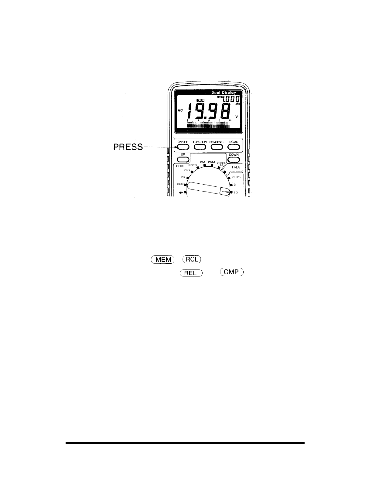
1. ON/OFF POWER ON/OFF
Press the ON/OFF(RED) button to turn the meter on. Press again to turn
the meter off.
Automatic Power-off
Automatic Power-off extends the life of the battery by turning the meter
off if neither the rotary switch nor a pushbutton is operated for 10 minutes.
However, during communication with a PC, Hi mode at capacitance, AC
mV range and dB measurement, power will not be turned off
automatically.
2. FUNCTION
Page 12

8 Manual Documentation Number M3640D1598
B&B Electronics -- PO Box 1040 -- Ottawa, IL 61350
PH (815) 433-5100 -- FAX (815) 433-5104
The sign
will be displayed on the LCD when you turn the power
on.
Press the FUNCTION button to enter the function mode. You can
select a function mode at your desire by pressing the FUNCTION
button and SET/RESET button by turns.
• Sequence of scroll in the Function modes
3. SET/RESET
Press the SET/RESET button to enter the selected function mode and press
again to exit. Then the
will be displayed on the LCD.
In the function modes of
and , the RESET function does
not work. To exit from these modes, you have to move the selector switch
to an adjacent range or press the function key.
4. DC/AC
Press DC/AC button to toggle between DC and AC when the rotary switch
is set to Voltage or Current.
5 & 6. UP DOWN
Press UP DOWN buttons to determine the polarity, value of the reference
value in the
and modes, to address the stored reference
value in the
and modes.
5-2. Items 7-8 describe the Sockets.
7. TRANSISTOR hFE
Insert the base, collector, and emitter pins in the correct sockets, as
marked.
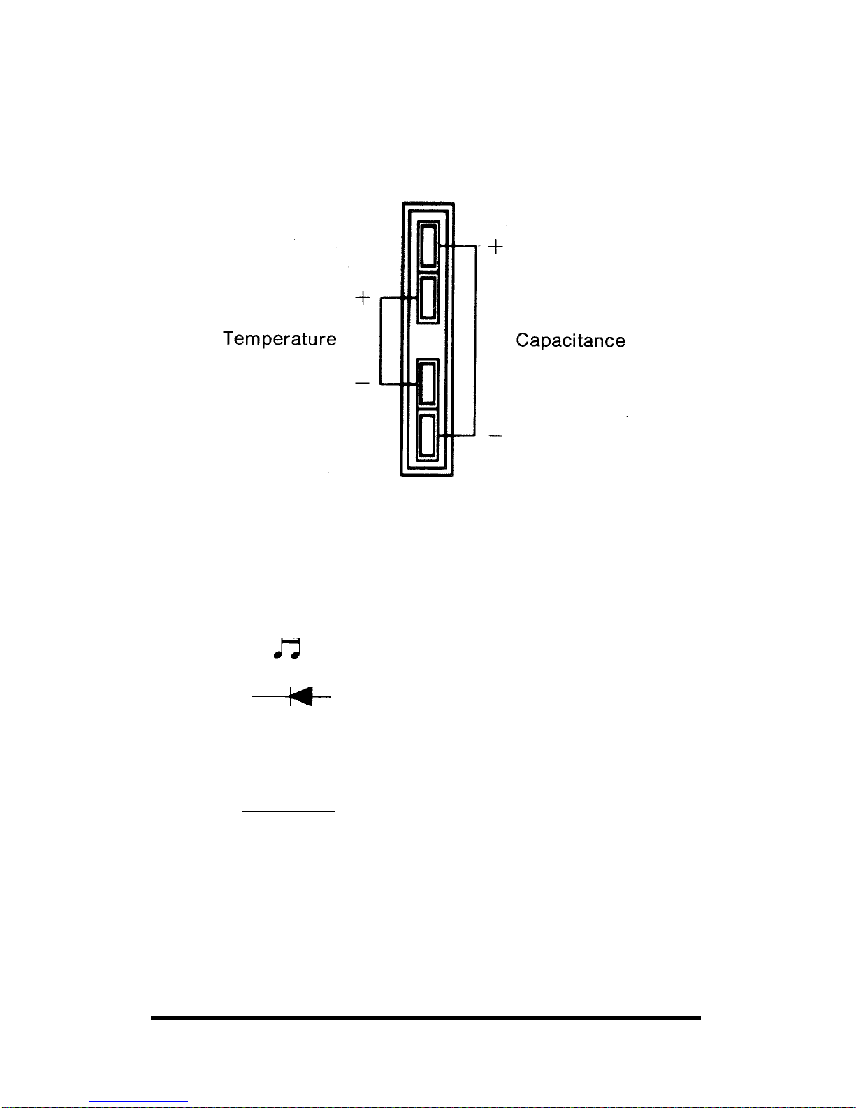
8. CAPACITOR (excluding M-3610D)
TEMPERATURE SOCKET (M-3640D/M-3660D only)
Page 13
Manual Documentation Number M3640D1598 9
B&B Electronics -- PO Box 1040 -- Ottawa, IL 61350
PH (815) 433-5100 -- FAX (815) 433-5104
Insert the discharged capacitor into the CAP + and - clips connectors, as
marked.
Insert the optional K-type thermocouples into the correct sockets, as
marked.
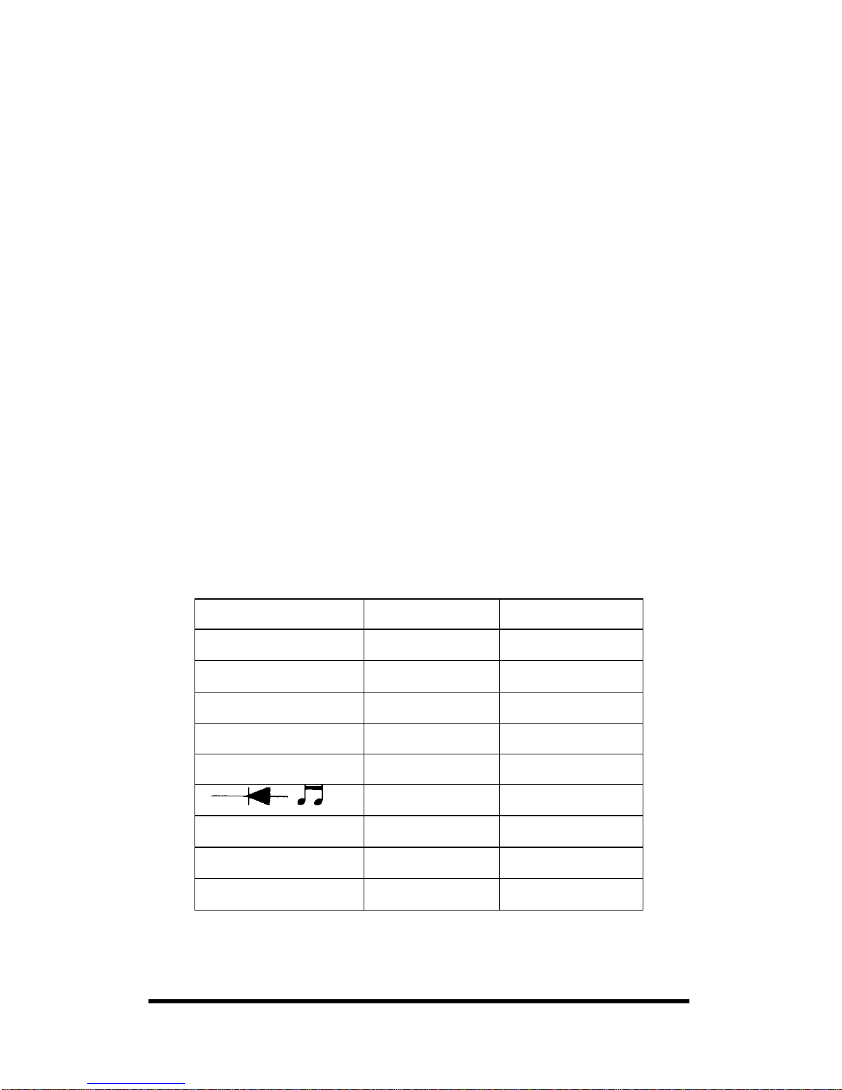
9. FUNCTION SELECTOR ROTARY SWITCH
Item 9 describes functions that are selected by setting the rotary switch.
mV Millivolts ac/dc
V Volts ac/dc
mA Milliampere ac/dc
A Amperes ac/dc
Continuity
Ω
Resistance
Diode Test
FREQ Frequency
CAP Capacitance
hFE Transistor
TEMP Temperature
HIGH
HOW
Logic Test
dB Decibel
Page 14

10 Manual Documentation Number M3640D1598
B&B Electronics -- PO Box 1040 -- Ottawa, IL 61350
PH (815) 433-5100 -- FAX (815) 433-5104
5-3. Input Terminals
Items 10-13 describe the input terminals (See Table 1 for overload limits.)
10. 20A Amperes Input Terminal
For current measurements (AC or DC) up to 20A when function selector
switch is in the 20A position.
11. mA Milliamp Input Terminal
For current measurements up to 200mA (AC or DC) when the function
selector switch is in the mA position.
12. COM Common Terminal
Return terminal for all measurements.
13. V/
ΩΩΩΩ
Continuity, Diode, Ohms, Volt, Frequency, dB, Logic Test Terminal.
5-4. Digital and Bar Graph Displays
Items 14-16 & 17 describe the digital and bar graph displays.
14. Digital Display
Digital readings are displayed on a 1999-count display with automatic
polarity indication and decimal point placement.
15.
Analog Bar Graph
The bar graph consists of 23 segments that illuminate from left to right as
the input increases.
It functions much the same as the needle on an analog meter without the
mechanical overshoot inherent in needle movements.
If the input equals or exceeds 1,999 counts on the range selected, OL is
displayed with flashing in the Bar-graph.
16.
Bar Graph Scale
Scale for absolute readings.
Page 15

Manual Documentation Number M3640D1598 11
B&B Electronics -- PO Box 1040 -- Ottawa, IL 61350
PH (815) 433-5100 -- FAX (815) 433-5104
17. OL Overload Indication
OL is displayed with flashing the bar-graph, when input is too excess to
display.
18.
Auto-Hold
The meter will freeze a reading automatically recorded 4 seconds ago,
when last reading is completed.
19.
Data-Hold
In this mode, you can freeze a reading on the sub-display by pressing the
SET/RESET button, and the subsequent reading wilI be displayed on the
main-display.
20.
Minimum
Lets you keep a minimum reading on the sub-display while showing the
present readings on the main-display.
21.
Maximum
Lets you keep a maximum reading on the sub-display while showing the
present readings on the main-display.
22.
Relative
Enables you to compare the reference value with a subsequent reading.
To set the reference value, follow these steps:
1. Set the function mode at
mode.
2. Store the polarity, values of the reference value you desire by pressing
the UP DOWN buttons and SET/RESET button by turns.
3. Press SET/RESET button for final setting.
Page 16

12 Manual Documentation Number M3640D1598
B&B Electronics -- PO Box 1040 -- Ottawa, IL 61350
PH (815) 433-5100 -- FAX (815) 433-5104
Example: Store Polarity +/ - (with UP/DOWN)
⇒ SET/RESET ⇒
Store 1st Value
⇒ SET/RESET ⇒
Store 2nd Value
⇒ SET/RESET ⇒
Store 3rd Value
⇒ SET/RESET ⇒
Store 4th Value
⇒ SET/RESET ⇒
4. To exit
mode, press the function key or turn the rotary switch to
an adjacent range.
Your meter will display the difference between the stored
reference value and subsequent readings on the sub-display
while showing the present measurement on the main-display.
For example, if the stored reference value is 100.0V and the present
reading is 90.0V, the sub-display will indicate - 10.0 V and the main
display will indicate 90.0V
If the new reading is the same as the reference value, the display will be
zero. In this mode, the total range of relative offset is 1999 counts.
23.
Memory
Enable you to memorize the reference values up to 10 measurements in the
meter.
To memorize the reference value, follow these steps:
1. Set the function mode at
mode.
2. Press UP DOWN buttons to address the number from 0 to 9.
3. Press SET/RESET button to memorize the reference value you desire.
If you memorize the reference values continuously under the
same address number, then the previous reference value will be
cleared automatically.
Page 17

Manual Documentation Number M3640D1598 13
B&B Electronics -- PO Box 1040 -- Ottawa, IL 61350
PH (815) 433-5100 -- FAX (815) 433-5104
24.
Memory Recall
Enables you to get the memorized reading back on the LCD.
To get the memorized reference value, follow these steps:
1. Set the function mode at
mode.
2. Press UP DOWN buttons to address the number from 0 to 9.
3. Press SET/RESET button to get the memorized value back on the
LCD. Then the reference value you chose will appear on the
sub-display.
25.
Dual-Display
Lets you have two primary+secondary readings on the LCD in the
following ranges (See Table 3)
Table 3. Dual-Display
INPUT RANGE MAIN-DISPLAY SUB-DISPLAY
AC VOLTAGE VOLTAGE FREQUENCY
FREQUENCY FREQUENCY AC VOLTAGE
TEMPERATURE
°C °F
LOGIC HI/LO FREQUENCY
dB dB AC VOLTAGE
Notes:
• Your meter will display Ripple Frequency at DC Voltage position.
• In the ranges of DC/AC A, Resistance, Diode and hFE, the sub-display
might show the FREQ .000. This is not intended for dual-display mode.
• When you select dual measurement while measuring frequency, the
meter selects the 20V AC range for the secondary display. To measure
both the voltage and frequency, when the voltage is greater than 20V
AC, select AC voltage as the primary measurement.
26.
Communication
Page 18

14 Manual Documentation Number M3640D1598
B&B Electronics -- PO Box 1040 -- Ottawa, IL 61350
PH (815) 433-5100 -- FAX (815) 433-5104
Allows you to interface the meter with your PC to communicate with your
PC in all function ranges. To avoid operation error, do not set your meter
at
mode during communicating with a computer.
27.
Comparison
Enables you to do the High Low Test of subsequent readings by comparing
a reading with both the stored high reference value and the stored low
reference value.
On the sub-display, Lo sign for reading less than the low reference value,
Hi sign for reading more than the high reference value and PASS sign for
middle ranges will be shown.
To store the reference values of Min/Max, see the steps of REL 2, 3.
To exit
mode, press the function key or turn the rotary switch to
an adjacent range.
28. Display for address number
To operate this address number, you can address the stored reference
values up to 10 measurements in the
and modes, each time
press UP DOWN buttons.
5-5. Annunciators
Items 29-32 describe annunciators that indicate the mode or state in which
the meter is operating.
29.
Diode Test
The value displayed is the forward voltage of semiconductor function(s) at
approximately 1 mA test current. Single 0-2.0V range.
30. AC Alternating Current or Voltage
31.
Continuity Check
Make it easy to check wiring, continuity of cables, fuses and connections.
etc.
32.
Negative Polarity
Automatically indicates negative inputs. When
is enabled,
indicates negative results of math calculations.
33. FREQ Frequency Count Mode
Can measure up to 1 MHz with 4 steps of 2, 20, 200KHz, 1 MHz (for
M-3610D/3630D/3640D).
Page 19

Manual Documentation Number M3640D1598 15
B&B Electronics -- PO Box 1040 -- Ottawa, IL 61350
PH (815) 433-5100 -- FAX (815) 433-5104
Can measure up to 20 MHz with 5 steps of 2, 20, 200KHz, 2, 20 MHz (for
M-3650D/3660D).
34. TEMP Temperature (M-3640D/M- 3660D only)
Can measure from -40° C to 1200°C by using the optional K-type
thermocouple.
35. CAP Capacitance (Except M-3610D)
Let you to measure capacitance from LO: nF 2, 2O, 200 to Hi: uF 2, 20,
200.
36. hFE Transistor hFE (Except M-3610D)
Enables you to measure hFE value.
37. LOG Logic Test
Enables you to check logic levels without extra logic probes. This function
displays Hi, Lo or ••• to indicate logic high, logic low, or undetermined,
respectively.
38. dB Decibels (M-3640D/3660D only)
Enables to check the logarithmic ratio of input voltage to the standard
stored value.
39. Sub-display
Lets you see the secondary readings in all function modes.
40.
Low Battery
Meter is powered by a single 9V battery. At least 8 hours of battery life
remain when
is first displayed.
Page 20

16 Manual Documentation Number M3640D1598
B&B Electronics -- PO Box 1040 -- Ottawa, IL 61350
PH (815) 433-5100 -- FAX (815) 433-5104
41. The following annunciators indicate the unit of the value displays:
AC Alternating current or voltage
DC Direct current or voltage
mV Millivolts (1x10
-3
volts)
V Volts
KHz Kilohertz (1x10
3
cycles) Frequency
MHz Megahertz(1x10
6
cycles) Frequency
°C
Centigrade Degree
°F
Fahrenheit Degree
uF Microfarads (10
-6
Farads)
nF Nanofarads (10
-9
Farads)
A Ampere (Amps) Current
mA Milliampere (1x10
-3
amps) Current
Ω
Ohm
KΩ
Kiloohm(1x10
3
)
MΩ
Megaohm (1x10
6
)
dB Decibels
Page 21

Manual Documentation Number M3640D1598 17
B&B Electronics -- PO Box 1040 -- Ottawa, IL 61350
PH (815) 433-5100 -- FAX (815) 433-5104
6. HOW TO MAKE MEASUREMENTS
This section discusses some common applications for your meter, and
alerts you to some considerations to keep in mind when making
measurements.
6-1. Measuring DC /AC Voltage
WARNING: DO NOT TRY TO MEASURE A VOLTAGE GREATER
THAN 1000 VOLTS DC OR 750 VOLTS AC. YOU MIGHT DAMAGE
YOUR METER AND EXPOSE YOURSELF TO A SEVERE SHOCK
HAZARD.
Follow these steps to measure DC/AC Voltage:
1. Set the rotary switch to the desired voltage position with 5 steps:
200mV, 2, 20, 200V(DC/AC) and 1 000V(DC), 750V(AC).
2. Press the DC/AC button to toggle between alternating and direct
voltage.
3. Connect the meter in parallel with the load or circuit.
Notes:
• Due to the sensitive nature of 200mV & 2V AC ranges, your meter
displays a small value. This residual value will not affect the actual
measurements.
• Each of the five dc/ac voltage ranges presents an input impedence of
approximately 10M Ω in parallel with less than 100pF. AC voltage in
ac-coupled to the 10M Ω input.
Page 22

18 Manual Documentation Number M3640D1598
B&B Electronics -- PO Box 1040 -- Ottawa, IL 61350
PH (815) 433-5100 -- FAX (815) 433-5104
6-2. Measuring Current
WARNING: YOU MAY DAMAGE THE METER OR BE INJURED IF
THE FUSE BLOWS WHILE CURRENT IS BEING MEASURED IN A
CIRCUIT WHICH EXHIBITS AN OPEN CIRCUIT VOLTAGE
GREATER THAN 250V. THE 20A TERMINAL IS FUSED. A SEVERE
FIRE HAZARD AND SHORT CIRCUIT DANGER EXISTS IF YOU
APPLY A VOLTAGE WITH HIGH-CURRENT CAPABILITY TO THIS
TERMINAL. THE METER CAN BE DESTROYED UNDER SUCH
CONDITI ONS.
Follow these steps to measure Current:
1. Set the rotary switch to the desired Ampere position with 5 steps of
200 µA, 2, 20, 200mA, 20A (for M-3630D/3650D) and with 4 steps of
200 µA, 2,200mA, 20A (for M-3610D) and with 3 steps of 2, 200mA,
20A (for M-3640/3660D).
2. Press the DC/AC button to toggle between alternating and direct
current.
3. Connect the meter in series with the load or circuit under test.
Page 23

Manual Documentation Number M3640D1598 19
B&B Electronics -- PO Box 1040 -- Ottawa, IL 61350
PH (815) 433-5100 -- FAX (815) 433-5104
Notes:
• If you do not know approximately what the current is, connect the circuit
to 20A input terminal first to see if you have a safe level for the mA
input terminal. Use the mA input terminal for Current up to 200mA.
• When measuring Current, the meter’s internal shunt resistors develop a
voltage across the meter’s terminals called "burden voltage". This
voltage drop is very low in your meter, but it may affect precision
circuits or measurements.
• If you set the meter for DC current,—appears or disappears to indicate
the polarity of the measured current.
6-3. Continuity Testing
Continuity testing verifies that circuit connections are intact. To perform
audible continuity tests, set the rotary switch to
and connect the meter
to your circuit.
Caution: Never perform a continuity measurement on a circuit that has
power connected.
Note: The buzzer sounds if the measured resistance is below 40 ohms.
Page 24

20 Manual Documentation Number M3640D1598
B&B Electronics -- PO Box 1040 -- Ottawa, IL 61350
PH (815) 433-5100 -- FAX (815) 433-5104
6-4. Measuring Resistance
WARNING: NEVER CONNECT THE TEST PROBES TO A SOURCE
OF VOLTAGE WHEN YOU HAVE SELECTED THE OHMS
FUNCTION AND PLUGGED THE PROBES INTO V/Ω TERMINAL.
BE SURE THAT THE CIRCUIT UNDER TEST HAS ALL POWER
REMOVED AND THAT ANY ASSOCIATED CAPACITORS ARE
FULLY DISCHARGED BEFORE YOU MAKE A RESISTANCE
MEASUREMENT.
Follow these steps to measure resistance:
1. Set the rotary switch to any of 200 Ohm to 2000 Mohm with 7 steps
(for Model M-3610D/3630D/3650D) or 200 to 20 Mohm with 6 steps
(for Model M-3640D/3650D)
2. Connect the test Ieads to the device you want to measure.
Notes:
• The resistance in the test leads can diminish accuracy on the lowest
(200-ohm) range. The error is usually 1 to 0.2 ohms for a standard pair
of test leads. To determine the error, short the test leads together and
read the resistance of the leads.
• When measuring resistance, be sure that the contact between the probes
and the circuit is good. Dirt, oil, solder flux, or other foreign matter
seriously affect resistance.
• If the measured resistance value exceeds the maximum value, OL
displays to indicate overload and the bar graph flashes.
• For resistance of approximately 1 Megaohm and above, the display
might take a few seconds to stabilize. This is normal for high resistance
readings.
Page 25

Manual Documentation Number M3640D1598 21
B&B Electronics -- PO Box 1040 -- Ottawa, IL 61350
PH (815) 433-5100 -- FAX (815) 433-5104
6-5 Checking Diode
This function lets you check diodes and other semiconductors for opens
and shorts. It also lets you determine the forward voltage for diodes. You
can use this function when you need to match diodes.
Follow these steps to check Diode
1. Rotate the rotary switch to position.
2. Plug the test probes into the COM and V/ Ω terminals.
3. Connect the test leads to the diode you want to check and note the
meter reading.
Notes:
• If the display indicates an overrange condition, reverse the polarity of
the connection.
• If the display shows a value, the device is good. The displayed value is
the components actual forward voltage (up to 2.0 volts).
• If the display still indicates an overrange condition, the device is open.
• If the display shows a value both before and after you reverse the
polarity, the device is shorted.
Page 26

22 Manual Documentation Number M3640D1598
B&B Electronics -- PO Box 1040 -- Ottawa, IL 61350
PH (815) 433-5100 -- FAX (815) 433-5104
6-6. Measuring Frequency
WARNING: IF YOU TRY TO MEASURE THE FREQUENCY OF A
SIGNAL THAT EXCEEDS 750 VOLTS AC RMS, YOU MIGHT
DAMAGE YOUR METER AND EXPOSE YOURSELF TO SEVERE
SHOCK HAZARD.
Follow these steps to measure the frequency of a signal.
1. Set the function selector to the FREQ position with 4 steps: 2, 20,
200KHz & 1 MHz (for M3610D/3630D/3640D) and 5 steps: 2, 20,
200 KHz, 2, 20 MHz (for M-3650D/3660D).
2. Plug the test probes into the COM and V/Q terminals.
3. Connect the test leads to the frequency source.
Caution: (M3610D/M3630D/M3640D)
• For measurement 200KHz above, neither interface the meter with a
P.C nor select the function mode COM. Doing so, your meter will
displays the ambiguous value.
Notes:
• When the test probes are connected to an AC outlet, do not turn the
function selector switch to another range. It may damage the internal
components, or you.
• Overload Protection: 750V DC/AC RMS
• Input limit voltage: AC 20V rms w/dual mode & PC interface.
• For the most accurate measurement, we strongly recommend you to use
the type of BNC cable.
Page 27

Manual Documentation Number M3640D1598 23
B&B Electronics -- PO Box 1040 -- Ottawa, IL 61350
PH (815) 433-5100 -- FAX (815) 433-5104
6-7. Measuring Capacitance
Follow these steps to measure capacitance normal:
1. Discharge each capacitor before testing by shorting its leads together.
Use caution when handling some capacitors, as they can be charged
with considerable electricity.
Caution: If you attempt to measure the capacitance of a charged
capacitor, you might damage your meter.
2. Set the rotary switch to either Lo or Hi of CAP range.
Lo: nF 2/20/200 High: µF 2/20/200
3. Insert the discharged capacitor into the CAP + and - clips connector.
Your meter displays the capacitance value.
Notes:
• For polarized capacitors, be sure to insert the negative lead in the —
(minus) clip.
• In this mode's Hi, the auto power off function does not work.
6-8. dB Measurement (M-3640D/3660D only)
WARNING: DO NOT TRY TO MEASURE A VOLTAGE GREATER
THAN 20V AC. YOU MIGHT DAMAGE YOUR METER AND
EXPOSE YOUR SELF TO A SEVERE SHOCK HAZARD.
Follow these steps to measure the dB (decibels)
1. Set the rotary switch to the desired position with 2 steps input
voltages: 200mV & 20 V AC range.
2. Connect the meter in parallel with the load or circuit.
Page 28

24 Manual Documentation Number M3640D1598
B&B Electronics -- PO Box 1040 -- Ottawa, IL 61350
PH (815) 433-5100 -- FAX (815) 433-5104
Notes:
• dB(decibels) in the display indicates the Logarithmic ratio of input
voltage to the standard stored value.
• During activation of dB measurement, the auto power off will not
work.
Table 4. Logorithmic ratio
INPUT VOLTAGE DB
0.075 mV -60 dB
109 mV -17 dB
1.94 V 8 dB
19.40 V 28 dB
6-9. Checking Transistors
WARNING: The transistor socket is not protected against overload. You
can damage the meter and void your warranty if you build and use external
leads for the transistor socket.
Follow these steps to determine a transistor's base gain:
1. Rotate the rotary switch to the hFE positon.
2. Insert the transistor you want to measure into the appropriate transistor
socket. Your meter displays the transistor’s hFE value.
Page 29

Manual Documentation Number M3640D1598 25
B&B Electronics -- PO Box 1040 -- Ottawa, IL 61350
PH (815) 433-5100 -- FAX (815) 433-5104
Notes:
• Insert the base, collector, and emitter pins into the correct sockets.
• Some power Darlington transistors contain internal base-to-emitter
resistors. Because the meter uses two current readings to calculate hFE,
any internal transistor resistance causes undependable readings.
• Do not take the hFE reading as an absolute measurement, but rather as
an indication that the transistor is operation. The true gain of a transistor
depends on its operating current. This meter applies up to 1000 uA to
the emitter and collector and measures the collector current to calculate
the hFE.
• You can’t measure the hFE of a transistor that is connected in a circuit.
• You cannot measure the hFE of a FET or other non-bipolar transistor.
• High-voltage junctions in power transistors prevent correct readings.
Also, the larger leads of the power transistor can damage the test socket.
• Do not try to determine type, pin-out, or hFE for power transistors with
this meter.
• hFE is affected by temperature. Try not to warm the transistor with your
hand when you instalI the device in the socket. If the hFE reading is not
stable when you first measure it, let the transistor’s temperature
stabilize.
6-10. Measuring Temperature (M-3640D / 3660D only)
The meter can directly display the temperature with dual-display by
reading Celsius in the main-display and Fahrenheit on the sub-display at
mode.
Temperature from -40°C to 1200°C can be measured by using optional
K-type thermocouple at TEMP position.
Page 30

26 Manual Documentation Number M3640D1598
B&B Electronics -- PO Box 1040 -- Ottawa, IL 61350
PH (815) 433-5100 -- FAX (815) 433-5104
6-11. Logic Test
The logic function lets you easily check digital circuits to determine the
logic state of different parts of the circuit. Rather than display an absolute
voltage, this function displays Hi, LO, or ••• indicate logic high, low, or
undetermined respectively.
Follow these steps to perform a logic test:
1. Rotate the rotary switch to the HIGH/LOW range.
2. Plug the test leads into the COM and V/Ω inputs.
3. Connect the black probe to the ground point (GND) of the test circuit
and the red probe to the supplying voltage point (V+). While keeping
the test probes firmly connected to each point, press SET/RESET
button.
4. While keeping a connection between the black probe and the circuits
GND point, move the red probe to the other desired points. The meter
immediately displays one of the 3 modes, as follows:
• If value exceeds above 70% of the stored value, the Hi (HIGH)
appears.
• If value falls below 30% of the stored value Lo (LOW) appears.
• If value is between stored reference value, ••• segment appears.
Notes:
• In this mode, the
and functions do not work.
• To set the reference value, the supplying voltage should be 3V or more,
The testing range of logic is limited from 0V up to 19.99V
Page 31

Manual Documentation Number M3640D1598 27
B&B Electronics -- PO Box 1040 -- Ottawa, IL 61350
PH (815) 433-5100 -- FAX (815) 433-5104
6-12. Using the Meter with a Computer
6-12-1 Interfacing the Meter with a Computer
Follow these steps to connect the meter to a computer:
1. Connect the supplied RS-232C cable between the meter's and the
computer's serial port, as shown.
2. Press ON/OFF to turn on the meter.
3. Turn on the computer.
6-12-2. Using the Supplied Software
We have included two programs to log and display data collected with
your meter. The MS-DOS program is called METEX, and is in the
GRAPHIC subdirectory on the supplied diskette. The Windows program is
called Scopeview, and is in the SCOPE directory on the supplied diskette.
Note: You cannot log frequencies on the computer if the voltage exceeds
20V AC.
6-12-3. Using the DOS Software
Follow these steps to install and run the MS-DOS software.
Note: The following steps assume a basic knowledge of MS-DOS
commands, and also assume you have a hard disk. Refer to your computer
s MS-DOS User s Guide for information about MS-DOS commands. This
software requires a VGA monitor.
1. Insert the supplied diskette in your computer’s drive.
2. Create a directory on your hard disk for the software. For example, to
make a directory called METER for the software, type:
cd \ <ENTER>
md METER <ENTER>
3. Make the directory you created the current directory. For example, if
the directory is METER, type:
cd\METER <ENTER>
4. Copy the files from the GRAPHIC subdirectory on the floppy drive to
your hard disk. For example, type:
Page 32

28 Manual Documentation Number M3640D1598
B&B Electronics -- PO Box 1040 -- Ottawa, IL 61350
PH (815) 433-5100 -- FAX (815) 433-5104
copy a: \ GRAPHIC c:
5. To run the program, type METEX <ENTER>. Follow the on-screen
help for specific operating instructions.
Notes:
• If you do not have a hard disk, you can still run the program from the
supplied floppy diskette. Change to the GRAPHIC subdirectory on the
diskette, and type METEX <ENTER>.
• To stop the program or to escape from a device I/O error, press
<CTRL+BREAK>.
6-12-4. Using the Windows Software
Follow these steps to install and run the Windows software.
Note: The following steps assume a basic knowledge of Microsoft
Windows. Refer to your computer's Windows User's Guide for information
about using Windows. This software requires Microsoft Window, Version
3.1 and a VGA or EGA display.
1. Start your computer and run Windows.
2. Insert the supplied diskette in your computer's drive.
3. From the Windows Program Manager, pull down the FILE menu and
select the RUN option.
4. At the prompt, type:
a:\scope\setup <ENTER> (If you placed the diskette in Drive A)
b:\scope\setup <ENTER> (If you placed the diskette in Drive B)
5. Follow the on-screen prompts to complete installation.
6. To run the program, double-click the SCOPEVIEW icon. Follow the
on-screen help for specific operating instructions.
Also, refer to the README file in the diskette s SCOPE subdirectory
for operation hints,
6-12-5. Technical Information
You need the following information if you are writing your own interface
software:
Communication parameters
• Transmission rate: 1200 baud
• Character coding 7-bit ASCII
• Parity None
• Stop Bits: 2
Page 33

Manual Documentation Number M3640D1598 29
B&B Electronics -- PO Box 1040 -- Ottawa, IL 61350
PH (815) 433-5100 -- FAX (815) 433-5104
Data Format
The data format consists of a frame of 14 bytes. The frames are set as
follows:
BYTE) 1 2 3 4 5 6 7 8 9 A B C D E
Example 1) D C —1 . 9 9 9 V CR
Example 2) 1 . 9 9 9 Mohm CR
Connection of MT/RS - 232C cable to the meter.
The following program is an example of a BASIC program that gets a
single reading from the meter:
10 OPEN"COM1: 1200, N, 7, 2, RS, CS, DS, CD" AS #2
20 A$ = “D”
30 PRINT #2, A$
40 IN$=INPUT$ (14, #2)
50 PRINT IN$
60 CLOSE #2
70 END
Page 34

30 Manual Documentation Number M3640D1598
B&B Electronics -- PO Box 1040 -- Ottawa, IL 61350
PH (815) 433-5100 -- FAX (815) 433-5104
7. CARE AND MAINTENANCE
Your digital multimeter is a precise electronic device. Do not tamper with
circuit. To prevent electric shock hazard, turn off the meter and disconnect
test leads before removing the back cover.
7-1. Replacing the Fuse
WARNING: TO AVOID ELECTRIC SHOCK, DISCONNECT THE
TEST PROBES BEFORE REMOVING THE BATTERY OR THE FUSE.
REPLACE ONLY WITH THE SAME TYPE OF BATTERY OR FUSE
DO NOT REMOVE THE TOP COVER. SERVICE SHOULD BE
PERFORMED ONLY BY QUALIFIED PERSONNEL.
CAUTION: FOR CONTINUED PROTECTION AGAINST FIRE OR
OTHER HAZARD, REPLACE ONLY WITH FUSE OF THE SPECIFIED
VOLTAGE AND CURRENT RATINGS.
Follow these steps to replace the fuse:
1. Press ON/OFF button to turn the meter off and disconnect the test
probes.
2. Remove the back cover by unscrewing the four screws and pulling off
the meter s cover.
3. Remove the blown fuse.
4. Install the new fuse in the fuse compartment.
5. Replace the back cover and secure it with the screws.
WARNING: DO NOT OPERATE YOUR METER UNTIL THE BACK
COVER IS IN PLACE AND FULLY CLOSED.
Page 35

Manual Documentation Number M3640D1598 31
B&B Electronics -- PO Box 1040 -- Ottawa, IL 61350
PH (815) 433-5100 -- FAX (815) 433-5104
7-2. General Maintenance
Any adjustments, maintenance, or repair of the instrument, except battery
and fuse replacement should be done only by qualified service personnel.
1. Keep your meter dry. If it does get wet, wipe it dry immediately.
Liquids might contain minerals that can corrode the electronic circuits.
2. Use and store your meter only in normal temperature environments.
Extreme temperatures can shorten the life of electronic devices,
damage battery, and distort or melt plastic parts.
3. Handle your meter gently and carefully. Dropping it can damage
circuit boards and cases and cause the meter to work improperly.
4. Keep your meter away from dust and dirt, which can cause premature
wear of parts.
5. Wipe your meter with a damp cloth occasionally to keep it looking
new. Do not use harsh chemicals, cleaning solvents, or strong
detergents to clean the meter.
6. Use only a brand-new battery of the same size and type. Always
remove an old or weak battery. It can leak chemicals that destroy
electronic circuits.
Modifying or tampering with your meter’s internal components can cause
a malfunction and might invalidate its warranty.
Page 36

32 Manual Documentation Number M3640D1598
B&B Electronics -- PO Box 1040 -- Ottawa, IL 61350
PH (815) 433-5100 -- FAX (815) 433-5104
8. SPECIFICATIONS
8-1. General Characteristics
• Max Display........................ 1999 Counts (3½ Digit) with automatic polarity indication
• Max Input Current of AC & DC................................................................................ 20A
• Reading Time................................................................................1-2 reading per second
• Operating Temperature..........................................................0°C to 40° (32°F to 104°F)
• Storage Temperature........................................................-10°C to 50°C (14°F to 122°F)
• Temperature for Guaranteed Accuracy....................................................... + 23°C ± 5°C
• Battery type..........................................................................NEDA 1604 9V or 6F22 9V
• Size (H x W x L).......................................................................................84x187x34mm
• Net weight................................................................... 305g±10g (Including 9V Battery)
• Supplied Accessories:.........................................................................Operating Manual,
pair of Test Leads,
Spare Fuse,
9V Battery.
• Optional Accessories: .............................................................................. Carrying Case,
Interface Cable MT/RS-232C,
Floppy disc with software,
K-type thermocouples.
Page 37

Manual Documentation Number M3640D1598 33
B&B Electronics -- PO Box 1040 -- Ottawa, IL 61350
PH (815) 433-5100 -- FAX (815) 433-5104
8-2 Special Characteristics
MODEL FUNCTION RANGE ACCURACY RESOLUTION
200 mV
2 V
20V
200V
±0.3% of rdg +1 dgt 100 uV
1 mV
10 mV
100 mV
DC VOLTAGE
1000 V ±0.5% of rdg +1 dgt 1 V
200 mV
2 V
20 V
200 V
±0.8% of rdg +3 dgts 100 uV
1 mV
10 mV
100 mV
AC VOLTAGE
750 V ±1.2% of rdg +3 dgts 1 V
200 Ω
2 KΩ
20 KΩ
200 KΩ
2 MΩ
±0.5% of rdg +3 dgts
0.1 Ω
1 Ω
10 Ω
100 Ω
1 KΩ
20 MΩ
±1.0% of rdg +2 dgts
10 KΩ
M-3610D
M-3630D
M-3650D
RESISTANCE
* 2000 MΩ
±5.0% of rdg +5 dgts
1 MΩ
Page 38

34 Manual Documentation Number M3640D1598
B&B Electronics -- PO Box 1040 -- Ottawa, IL 61350
PH (815) 433-5100 -- FAX (815) 433-5104
MODEL FUNCTION RANGE ACCURACY RESOLUTION
200 uA
2 mA
20 mA
±0.5% of rdg +1 dgt 0.1 uA
1 uA
10 uA
200 mA ±1.2% of rdg +1 dgt 100 uA
DC CURRENT
20 A ±2.0% of rdg +5 dgt 100 mA
200 uA
2 mA
20 mA
±1.0% of rdg +3 dgts 0.1 uA
1 uA
10 uA
200 mA ±1.8% of rdg +5 dgts 100 uA
M-3610D
M-3630D
M-3650D
AC CURRENT
20 A ±3.0% of rdg +5 dgts 10 mA
Notes: 1. DC/AC Current
20 mA – Not available in M-3610D
Page 39

Manual Documentation Number M3640D1598 35
B&B Electronics -- PO Box 1040 -- Ottawa, IL 61350
PH (815) 433-5100 -- FAX (815) 433-5104
MODEL FUNCTION RANGE ACCURACY RESOLUTION
2 KHz
20 KHz
200 KHz
±1.0% of rdg +1 dgt 1 Hz
10 Hz
100 Hz
1 MHz ±1.0% of rdg +1 dgt 1 KHz
FREQUENCY
* 2 MHz
* 20 MHz
±1.0% of rdg +1 dgt 1 KHz
10 KHz
2 nF ±2.0% of rdg +10 dgts 1 pF LOW
20 nF
200 nF
±2.0% of rdg +3 dgts 10 pF
100 pF
2 uF ±3.0% of rdg +10 dgts 1 nF
20 uF ±3.0% of rdg +5 dgts 10 nF
CAPACITANCE
HIGH
200 uF ±4.0% of rdg +5 dgts 100 nF
M-3610D
M-3630D
M-3650D
DIODE
Measures forward resistance of a semiconductor junction in
KΩ a test current of 1 mA.
Notes: 1. FREQUENCY: *Not available in M-3610D & M630D.
2. CAPACITANCE: Not available in M-3610D.
Page 40

36 Manual Documentation Number M3640D1598
B&B Electronics -- PO Box 1040 -- Ottawa, IL 61350
PH (815) 433-5100 -- FAX (815) 433-5104
8-2. Special Characteristics
MODEL FUNCTION RANGE ACCURACY RESOLUTION
200 mV
2 V
20V
200V
±0.3% of rdg +1 dgt 100 uV
1 mV
10 mV
100 mV
DC VOLTAGE
100 V ±0.5% of rdg +1 dgt 1 V
200 mV ±0.8% of rdg +3 dgts 100 uV
2 V
20 V
200 V
±2.5% of rdg +5 dgts 1 mV
10 mV
100 mV
AC VOLTAGE
(True rms)
750 V ±1.5% of rdg +3 dgts 1 V
200 Ω
2 KΩ
20 KΩ
200 KΩ
2 MΩ
±0.5% of rdg +3 dgts
0.1 Ω
1 Ω
10 Ω
100 Ω
1 KΩ
M-3640D
M-3660D
RESISTANCE
20 MΩ
±1.0% of rdg +2 dgts
10 KΩ
Notes: AC Voltage (True rms)
1. The nominated accuracy is guaranteed when the input value is full-scale basis.
2. Frequency for accuracy
• 40 Hz to 20 KHz for 200 mV, 2V, 20V & 200V.
• 40 Hz to 400 Hz for 750 V.
Page 41

Manual Documentation Number M3640D1598 37
B&B Electronics -- PO Box 1040 -- Ottawa, IL 61350
PH (815) 433-5100 -- FAX (815) 433-5104
MODEL FUNCTION RANGE ACCURACY RESOLUTION
2 mA ±0.5% of rdg +1 dgt 0.1 uA
1 uA
10 uA
200 mA ±1.2% of rdg +1 dgt 100 uA
DC CURRENT
20 A ±2.0% of rdg +5 dgts 100 mA
2 mA ±1.0% of rdg +3 dgts 0.1 uA
1 uA
10 uA
200 mA ±1.8% of rdg +5 dgts 100 uA
AC CURRENT
20 A ±3.0% of rdg +5 dgts 10 mA
-40°C~200°C ±3.0% of rdg +5 dgts
TEMPERATURE
200°C~1200°C ±3.0% of rdg +2 dgts
1°C
M-3640D
M-3660D
dB
200 mV
20 V
±3.0% of rdg +5 dgts 0.1 dB
Notes: AC Current
Frequency for accuracy
• 40 Hz to 10 KHz for 2 mA & 200 mA ranges.
• 40 Hz to 1 KHz for 20A range.
Page 42

38 Manual Documentation Number M3640D1598
B&B Electronics -- PO Box 1040 -- Ottawa, IL 61350
PH (815) 433-5100 -- FAX (815) 433-5104
MODEL FUNCTION RANGE ACCURACY RESOLUTION
2 KHz
20 KHz
200 KHz
±1.0% of rdg +1 dgt 1 Hz
10 Hz
100 Hz
1 MHz ±1.0% of rdg +1 dgt 1 KHz
FREQUENCY
* 2 MHz
* 20 MHz
±1.0% of rdg +1 dgt 1 KHz
10 KHz
2 nF ±2.0% of rdg +10 dgts 1 pF LOW
20 nF
200 nF
±2.0% of rdg +3 dgts 10 pF
100 pF
2 uF ±3.0% of rdg +10 dgts 1 nF
20 uF ±3.0% of rdg +5 dgts 10 nF
CAPACITANCE
HIGH
200 uF ±4.0% of rdg +5 dgts 100 nF
M-3640D
M-3660D
DIODE
Measures forward resistance of a semiconductor junction in
KΩ a test current of 1 mA.
Note: FREQUENCY: *Not available in M-3640D.
Page 43

Manual Documentation Number M3640D1598 39
B&B Electronics -- PO Box 1040 -- Ottawa, IL 61350
PH (815) 433-5100 -- FAX (815) 433-5104
WARRANTY
Warrants this instrument to be free from defects in material and workmanship for a period of one year. Any instrument found
defective within this period from the delivery date and, returned to the factory with transportation charges prepaid will be repaired,
adjusted, or replaced at no charge to the original purchaser. This warranty does not cover expendable items such as batteries or fuses.
If the defect has been caused by misuse or abnormal operating conditions the repair will be billed at a nominal cost.
 Loading...