

Page 1
LDVDSV2 Data Sheet v1.03 Page 1
www.bb-elec.com orders@bb-elec.com support@bb-elec.com
International Office: 707 Dayton Road PO Box 1040 Ottawa, IL 61350 USA 815-433-5100 Fax 433-5104
European Office: Westlink Commercial Park Oranmore Co. Galway Ireland +353 91 792444 Fax +353 91 792445
PRODUCT INFORMATION B&B ELECTRONICS
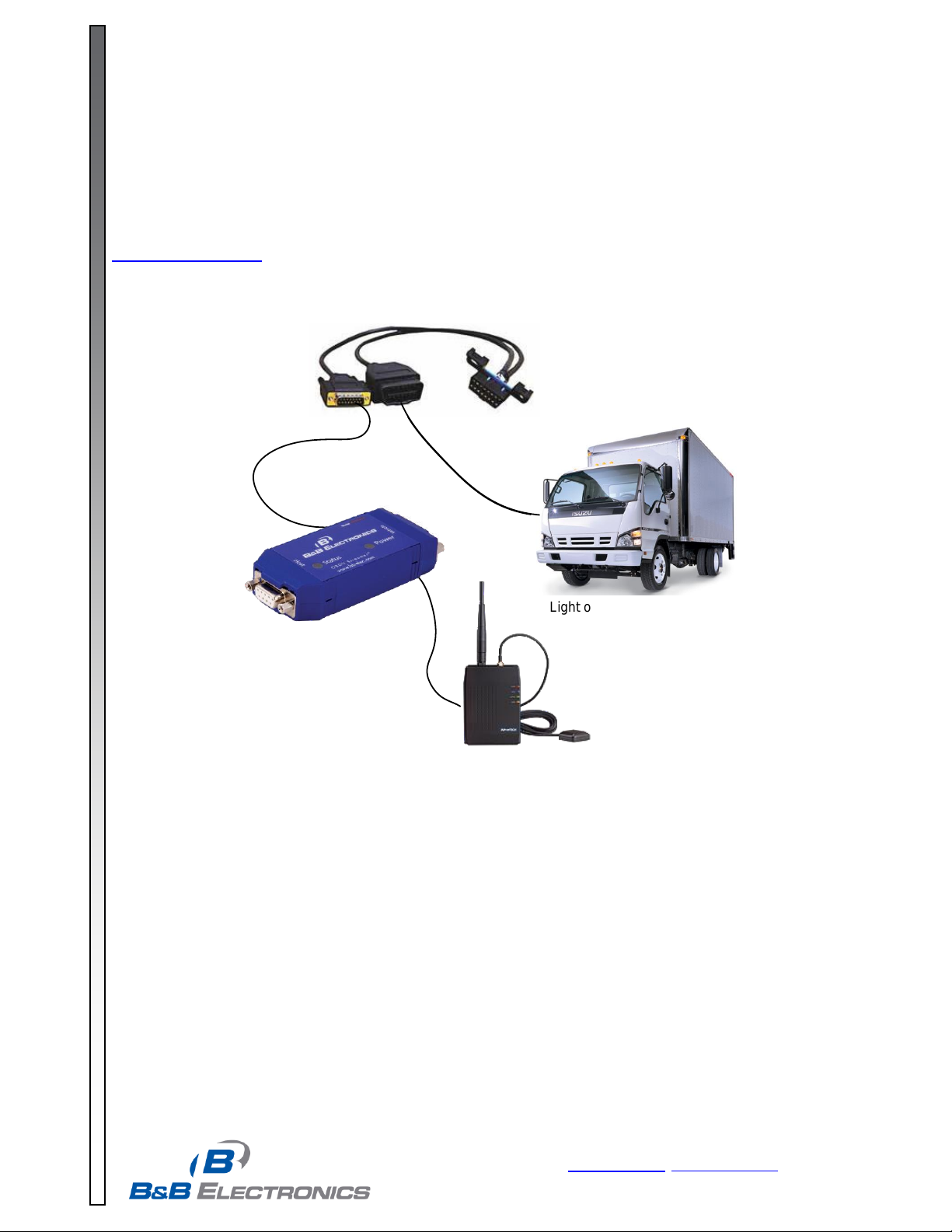
On-Board Computer
w/GPS & Wireless
Light or Medium Duty Car or
Truck
OBDII Y-Cable
RS-232
On-Board Computer
w/GPS & Wireless
Light or Medium Duty Car or
Truck
OBDII Y-Cable
RS-232
RS-232
Model LDVDSV2
The B&B Electronics AutoTap™ OBDII Data Streamer Model LDVDSV2 connects your PC, driver terminal, Java-enabled
phone, or other on-board computing device to the OBDII diagnostic bus of light and medium duty vehicles. It enables the
retrieval of the most commonly used parameters of value in telematics and fleet management applications.
The LDVDSV2 provides a simple operational protocol to communicate to the OBDII bus. It provides a common interface and
deterministic response time for all vehicles. The complete Command and Response protocol is published on B&B’s website
www.rvdstreamer.com.
Advanced OBDII Data Streamer
Supported Vehicles
The OBDII Streamer supports any 1996 or newer
vehicles that comply with the SAE’s J1979 OBDII
specification.
Supported Parameters
Vehicle Identification Number
Vehicle Speed - Monitor aggressive driving
Engine Speed - Monitor idle time and engine
abuse
Throttle Position
Odometer/Distance Traveled - Monitor trip
distance and HOS
Instantaneous Fuel Rate in Gallons per Hour
Total Fuel - Monitor MPG & Protect against theft
Ignition status – Track Idle time
Supported Protocols
SAE J1850 VPW
SAE J1850 PWM
SAE J2284/ ISO 15765 (CAN)
ISO 9141-2
ISO 14230-4 (KWP2000)
Battery Voltage – Watch for charging system failures
PTO Status - Automatically figure fuel tax savings
Diagnostic Trouble Codes
MIL Status
Emissions Readiness Monitors - Check remotely if
vehicles are ready for emissions certification
Brake Switch Status and Seatbelt Fastened available
on most Ford & GM trucks/vans
Other parameters available on a custom basis
Page 2
LDVDSV2 Data Sheet Page 2
www.bb-elec.com orders@bb-elec.com support@bb-elec.com
International Office: 707 Dayton Road PO Box 1040 Ottawa, IL 61350 USA 815-433-5100 Fax 433-5104
European Office: Westlink Commercial Park Oranmore Co. Galway Ireland +353 91 792444 Fax +353 91 792445
PRODUCT INFORMATION B&B ELECTRONICS
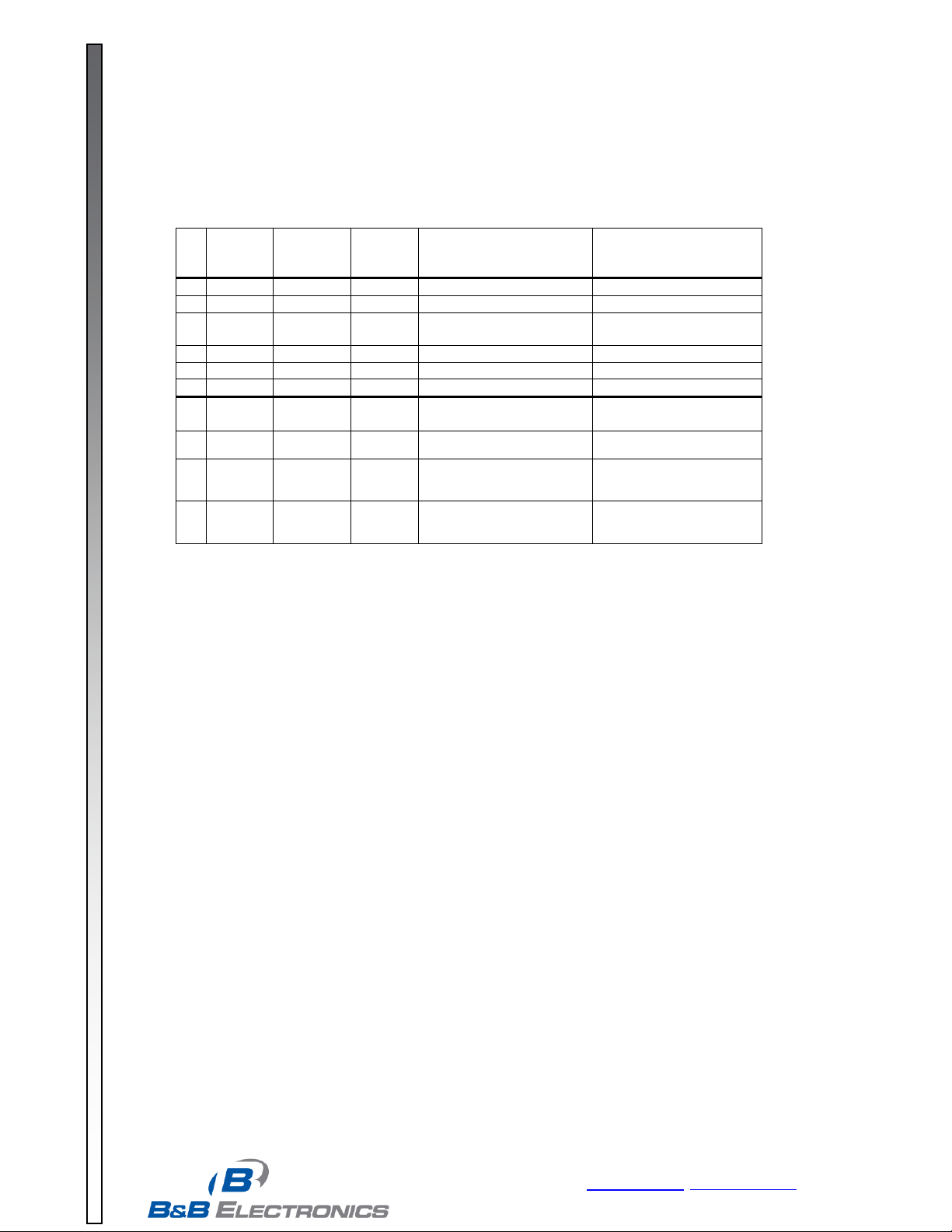
Red
LED
(Power)
Green
LED
(Activity)
Red
LED
(Debug)
Actual State
Customer Description
1
On
On
Off
Normal operation
Normal operation
2
On
SB
Off
Detecting vehicle
Detecting vehicle
3
Off
FB
Off
Database version mismatch
Database needs to be
updated
4
Off
SB
Off
Update in progress
Update in progress
5
Off
VSB
VSB
Device asleep
Device asleep
6
Off
Off
Off
Device unpowered
Device unpowered
7
Off
On
FB
Error FPGA Image Invalid
Firmware needs to be
updated
8
Off
Off
FB
Error with EMM code
Update System Manager
9
Off
Off
FB
EMM checking CRC of
Images
Wait 10 seconds if state
does not change see 8
10
Off
SB
FB
Error writing/reading
to/from flash during update
Restart update of current
component
Vehicle Speed Signal Output pulse for driving external distance meters
o 0V to 5V pulses, 1 kOhm output impedance.
o 50% Duty Cycle
o 3,500 pulses/km (5,632.7 pulses/mi.)
Ignition-On Signal Output
Status LED’s for vehicle connection and power
Additional Features
LED state descriptions:
On (LED_ON): lit, solid
Off (LED_OFF): unlit
FB (LED_FAST): Alternating on-off; 125ms on, 125ms off
SB (LED_SLOW): Alternating on-off; .5 sec on, .5 sec off
VSB (LED_VERY_SLOW): Alternating on-off; .25 sec on, 2 sec off
Automatic low power mode senses when vehicle speed & engine speed is zero.
Automatic disconnect when technician scan tool is connected (Requires separate OBDII Y-Cable)
Proprietary vehicle detection algorithm and embedded database lets the same hardware work on all compliant vehicles
Configurable parameter reporting by polling, at a fixed rate, or when a threshold is exceeded.
Wide Operating Temperature: -40 to 85 ºC (-40 to 185 ºF)
Low Power Consumption: 2W in Operating Mode; 0.15W in Automatic Sleep Mode (Key Off)
Page 3

LDVDSV2 Data Sheet Page 3
www.bb-elec.com orders@bb-elec.com support@bb-elec.com
International Office: 707 Dayton Road PO Box 1040 Ottawa, IL 61350 USA 815-433-5100 Fax 433-5104
European Office: Westlink Commercial Park Oranmore Co. Galway Ireland +353 91 792444 Fax +353 91 792445
PRODUCT INFORMATION B&B ELECTRONICS
Available Form Factors
Vehicle Bus Connection: DB15 female
Pin 1 ISO9141 K/
Pins 4, 5: J1850-, J1850+
Pin 6, 7 Ground
Pin 9 Vehicle unswitched Vbat
Pin 10 ISO9141 L
Pin 11 Vehicle Vbat to external scan tool
Pin 12 CAN Low
Pin 13 CAN High
RS-232 Connection: DB9 female, DCE
Pins 1,4,6 Connected together
Pin 2 RD
Pin 3 TD
Pin 5 Ground
Pin 7 RTS
Pin 8 CTS (Vehicle Ignition Status)
Pin 9 Vehicle Speed Sensor Output Signal, VBAT Power in, VBAT Power out (3 separate build options)
Dimensions: 4.1 x 1.7 x 0.8 in (104.1 x 43.2 x 20.3 mm)
Operating Voltage Range: 8 to 30 VDC
Calculated MTBF: 111,440 Hours
Page 4

LDVDSV2 Data Sheet Page 4
www.bb-elec.com orders@bb-elec.com support@bb-elec.com
International Office: 707 Dayton Road PO Box 1040 Ottawa, IL 61350 USA 815-433-5100 Fax 433-5104
European Office: Westlink Commercial Park Oranmore Co. Galway Ireland +353 91 792444 Fax +353 91 792445
PRODUCT INFORMATION B&B ELECTRONICS
1.750"
0.078" Max.
1.750"
0.110" Max.
2.0 mm
2
1
24
23
0.382"
ø 0.103" x4
0.075"
0.267"
Daughter Board Module
Connector:
24-Pin Header
0.5mm Square Pins
2.0mm Pin Spacing
Samtec P# TMM-112-06-T-D-SM
Suggested Stand-Off:
Page 5

LDVDSV2 Data Sheet Page 5
www.bb-elec.com orders@bb-elec.com support@bb-elec.com
International Office: 707 Dayton Road PO Box 1040 Ottawa, IL 61350 USA 815-433-5100 Fax 433-5104
European Office: Westlink Commercial Park Oranmore Co. Galway Ireland +353 91 792444 Fax +353 91 792445
PRODUCT INFORMATION B&B ELECTRONICS
Signal
Pin
Direction
Description
Serial Rx
1
Board to Streamer
0 to 3.3V Asynchronous serial signal (0V = Space, +5V = Mark)
Max Voltage 3.3V
Serial Tx
2
Streamer to Board
0 to 3.3V Asynchronous serial signal (0V = Space, +5V = Mark)
Max Voltage 3.3V
+5V 3 Board to Streamer
Regulated (+/-5%) 5V Supply @ 200 mA Max
Max Voltage 5.5V
Enable
4
Board to Streamer
OBDII Streamer Enable/Reset Pin (0-5V, Enabled = High)
Max Voltage 5V
Engine On
5
Streamer to Board
Indicates RPM or Vehicle Speed > 0
Vehicle Speed Pulse
6
Streamer to Board
0 to 5V signal with frequency proportional to vehicle speed
J1850+ 7 Both
J1850+ line from J1962 Pin 2
J1850- 9 Both
J1850- line from J1962 Pin 10
CANh 8 Both
CAN High line from J1962 Pin 6
CANl
10
Both
CAN Low line from J1962 Pin 14
ISO K
11
Both
ISO 9141 K Line from J1962 Pin 7
ISO L
12
Both
ISO 9141 L Line from J1962 Pin 15
Scan Tool Present
13
Streamer to Board
Indicates a technician scan tool has been plugged in
Max continuous voltage 45V
Max transient voltage 65V
Vbat
14
Board to Streamer
Vehicle battery voltage from J1962 Pin 16
+12V to Service Tool
15
Streamer to Board
+12V out to 3rd party scan tool
GND
16
Both
Vehicle battery ground from J1962 Pin 4 and 5
PGC
17
Board to Streamer
Microchip ICSP Clock for programming & debug
PGD
18
Both
Microchip ICSP Data for programming & debug
MCLR
19
Board to Streamer
Microchip ICSP MCLR/Program Voltage for programming & debug
+3.3V
20
Streamer to Board
+3.3V supply for Microchip ICSP programming & debug
TDI
21
Board to Streamer
JTAG data pin for FPGA programming & debug
TDO
22
Streamer to Board
JTAG data pin for FPGA programming & debug
TMS
23
Board to Streamer
JTAG pin for FPGA programming & debug
TCK
24
Board to Streamer
JTAG clock pin for FPGA programming & debug
Page 6
LDVDSV2 Data Sheet Page 6
www.bb-elec.com orders@bb-elec.com support@bb-elec.com
International Office: 707 Dayton Road PO Box 1040 Ottawa, IL 61350 USA 815-433-5100 Fax 433-5104
European Office: Westlink Commercial Park Oranmore Co. Galway Ireland +353 91 792444 Fax +353 91 792445
PRODUCT INFORMATION B&B ELECTRONICS
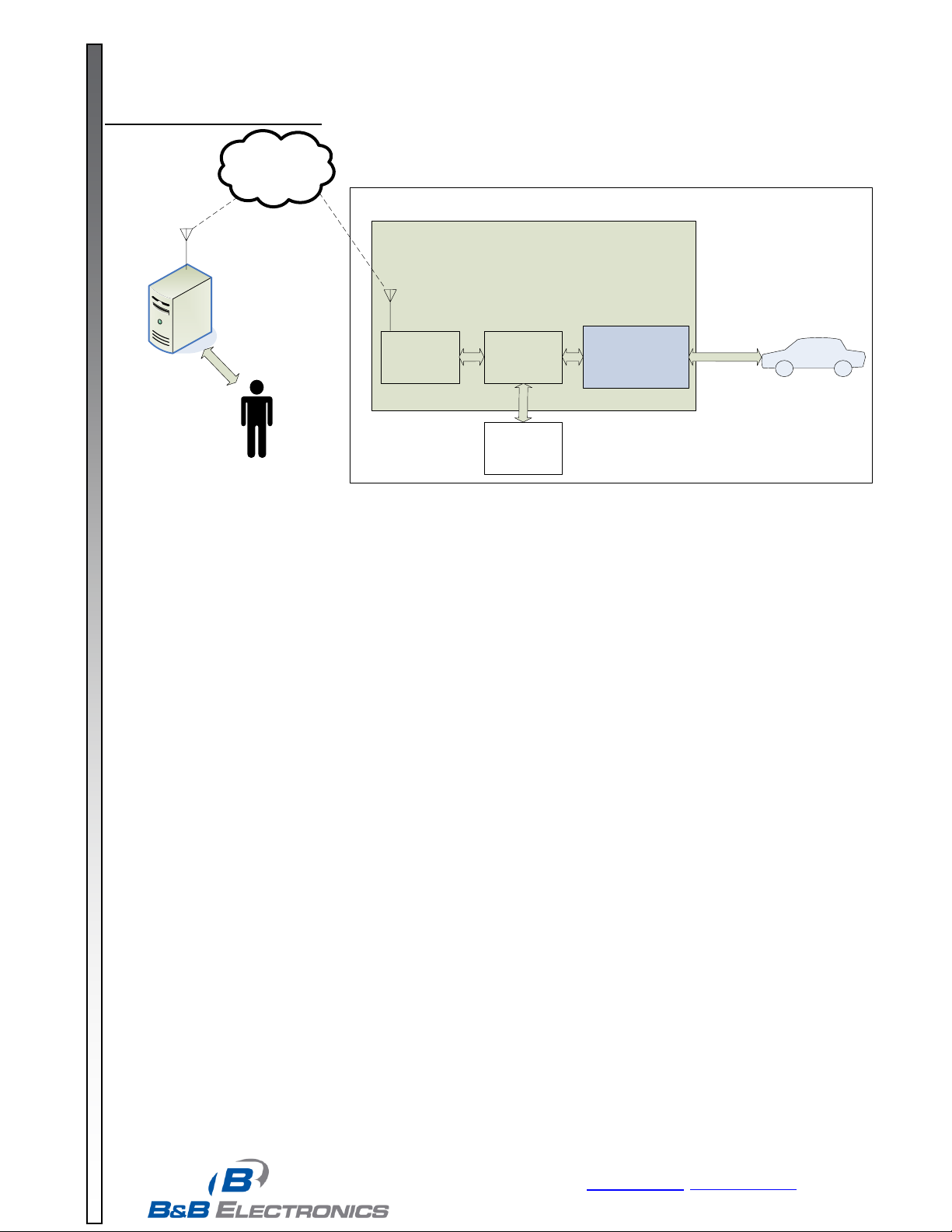
Vehicle Data
OBDII Streamer
Module
OBDII
Diagnostic
Busses
Data
Acquisition
& Storage
Cellular Network
Or
WiFi to Internet
On-Vehicle System
Wireless
Connectivity
Central
Server/
Database
Fleet Manager
Other
Sensors &
Displays
On-Board
Computing
Device
Mount Your Own Chip Set
Included:
Bill of Materials with manufacturer part numbers and suggested vendor information
Schematic in Adobe Acrobat and P-CAD Schematic Formats
Net List
PCBD Layout in Adobe Acrobat, P-CAD PCB, & Gerber Formats
Hex file with hardware description and firmware
Serial interface command and response specifications
External box w/OBDII Y-Cable to be used in application development.
QuickTester PC application w/source code
Unlimited Layout & Integration support for 1 year.
Maintenance releases and vehicle upgrades for 1 year.
Production test specifications.
Production test software w/source code
Page 7

LDVDSV2 Data Sheet Page 7
PRODUCT INFORMATION B&B Electronics
ELECTRONICS
www.bb-elec.com orders@bb-elec.com support@bb-elec.com
International Office: 707 Dayton Road PO Box 1040 Ottawa, IL 61350 USA 815-433-5100 Fax 433-5104
European Office: Westlink Commercial Park Oranmore Co. Galway Ireland +353 91 792444 Fax +353 91 792445
Product
B&B Supplied Items
Customer Requirements
Advantages
Disadvantages
Pricing Model
Box
Interface external box
Optional OBDII Y-Cable
On-board computer (OBC) with
RS-232 Serial Port
Software to read/write to serial
port
Quickest time to market
No hardware modification required to
the OBC
Automatic updates to new units
Most expensive solution
Two cables in the installation
Can’t test OBC/OBDII combination
until install
Per-piece hardware price
Daughter
Board
OBDII module with plug-
in interconnect &
mounting holes
Optional OBDII Y-Cable
OBC with TTL serial port,
matching plug-in interconnect, 5V
Supply, DB-15 connector to go to
OBDII Y-Cable.
Software to read/write to serial
port
Minimal software integration.
Reduce steps of installation
Less expensive than box
Automatic updates to new units
Test OBC/OBDII combination in the
factory at build time
PCBD Change required on OBC
OBC enclosure has to accommodate
daughter board
Possibly more expensive than chip
set.
Per-piece hardware price
Chip Set
Schematic
Bill of Materials
Example layout
FPGA HW Description
Firmware in executable
form
Integrate Streamer design into
the OBC.
Software to read/write to serial
port
Source OBDII chip set for
production
Minimal software integration.
Reduce steps of installation
Can lay out OBC PCBD to fit best in
enclosure
Possibly less expensive than daughter
board
Test OBC/OBDII combination in the
factory at build time
Extensive PCBD layout on OBC
Software updates for OBDII have to
be implemented in customer
production
Any hardware updates require a new
PCBD layout for the OBC.
Requires high quantities of chip set
purchase to get cost savings.
Replicates processors compared to IP
version.
First year NRE
Consecutive year
maintenance fee
Per-piece license fee
IP Libraries
Firmware in library form
(CAN Only)
Embedded Database
(CAN Only)
Design a CAN interface into the
OBC
Write an interface between the
Streamer libraries and the OBC
application.
Write board support libraries
between the Streamer libraries
and the OS/Hardware.
No redundant hardware costs.
Can achieve a small form factor.
No support for vehicles without CAN
(older than 2008)
Extensive software integration
required.
Hardware CAN interface design
required.
Longest time to market
Software updates for OBDII have to
be integrated into software before
production
First year NRE
Consecutive year
maintenance fee
Per-piece license fee
Choosing the right Product:
Page 8

LDVDSV2 Data Sheet Page 8
www.bb-elec.com orders@bb-elec.com support@bb-elec.com
International Office: 707 Dayton Road PO Box 1040 Ottawa, IL 61350 USA 815-433-5100 Fax 433-5104
European Office: Westlink Commercial Park Oranmore Co. Galway Ireland +353 91 792444 Fax +353 91 792445
PRODUCT INFORMATION B&B ELECTRONICS
EMC Testing
Radiated RF Interference: SAE J1113/41
Load Dump and Transient Protection SAE J1113/11
ESD Immunity SAE J1113/13
Environmental Testing
Temperature Test:
Ten (10) temperature cycles as follows with unit operating normally
1. Room (25ºC) to Tmin in 15 minutes.
2. Soak at Tmin 1 Hour with power removed from unit
3. Start unit at Tmin, confirm successful start by executing a command/response. Power-down unit. Maintain unit unpowered for one minute between power-ups.
4. Repeat Step 3 three times
5. Start unit at Tmin and ramp Tmin to Tmax in 30 minutes
6. Operate at Tmax for 1 hour
7. Ramp Tmax to Tmin in 15 minutes
8. Repeat steps 1 through 7 nine times for a total of 10 cycles:
a. 5 cycles at Vmin input
b. 5 cycles at Vmax input
Vibration Test:
IEC 60068-2-6
10 sweeps of 10 to 500 to 10Hz at rate 0.5 oct/min. each axis.
Level to be 10 to 36Hz, 0.06 in DA 36 to 500Hz, 4g’s
Unit must remain operational during and after the test.
Shock Test:
IEC 60068-2-27
18 to 50g’s, 11ms, ½ sine pulses, 3 each direction each axis
Unit must remain operational during and after the test.
Drop Test:
IEC 60068-2-32
10 Freefall drops from 1 meter onto concrete surface.
Drop 1 time one each face (6), 1 on a corner and the 3 edges of this corner.
The drop unit shall return to normal operation without physical damage.
 Loading...