

Page 1

OBDII Streamer Command & Response
V2.11
OBDII STREAMER FAMILY
User Implementation Document
Page 1/49
Page 2

OBDII Streamer Command & Response
V2.11
Table of Contents
Table of Contents ................................................................................................................ 2
Document Revision History ................................................................................................ 4
Communication Protocol Definition ................................................................................... 5
Overview ............................................................................................................................. 6
Startup Procedure ................................................................................................................ 6
Non-Volatile Storage .......................................................................................................... 7
Transferring to a New Vehicle ............................................................................................ 7
Ignition Detection ............................................................................................................... 7
Low Power Modes .............................................................................................................. 8
Settings ................................................................................................................................ 9
Overview ......................................................................................................................... 9
Time Based Updates ................................................................................................... 9
Threshold Based Updates ........................................................................................... 9
As Requested Updates ................................................................................................ 9
BAUD ............................................................................................................................. 9
OEM_ID ......................................................................................................................... 9
Update Mode ................................................................................................................. 10
Enable_Parameters ........................................................................................................ 10
Parameters ......................................................................................................................... 11
0x00 Vehicle Speed ...................................................................................................... 12
0x01 Engine Speed ....................................................................................................... 12
0x02 Throttle Position................................................................................................... 12
0x03 Odometer.............................................................................................................. 12
0x04 Fuel Level ............................................................................................................ 12
0x07 Engine Coolant Temp .......................................................................................... 13
0x08 Ignition Status ...................................................................................................... 13
0x09 MIL Status ........................................................................................................... 13
0x0C Fuel Rate ............................................................................................................. 13
0x0D Battery Voltage ................................................................................................... 13
0x0E PTO Status ........................................................................................................... 13
0x0F Seatbelt Fastened ................................................................................................. 13
0x10 — 0x1A Monitors ................................................................................................ 14
0x1B Brake Switch Status ............................................................................................ 14
0x22 Trip Odometer ...................................................................................................... 14
0x23 Trip Fuel Consumption ........................................................................................ 14
Commands ........................................................................................................................ 15
0x02 – READ_MODEL_NUMBER ............................................................................ 15
0x03 – GET_COMPONENT_VERSIONS .................................................................. 16
0x04 – OBDII_FIRMWARE_VERSION (Obsolete) .................................................. 17
0x05 – FIRMWARE_VERSION (Deprecated) ........................................................... 17
0x06 – DATABASE _VERSION (Deprecated) .......................................................... 18
0x07 – READ_SERIAL_NUMBER............................................................................. 19
0x09 – CONFIG_OEM_ID .......................................................................................... 20
0x15 – SERIAL_BAUD ............................................................................................... 21
Page 2/49
Page 3

OBDII Streamer Command & Response
V2.11
0x20 – GET_SUPPORTED_PARAMETERS ............................................................. 22
0x21 – ENABLE_PARAMETERS .............................................................................. 23
0x22 – GET_PARAMETER......................................................................................... 25
0x23 – GET_VEHICLE_STATUS............................................................................... 27
0x24 – REDETECT_VEHICLE ................................................................................... 28
0x25 – GET_VEHICLE_INFO .................................................................................... 29
0x30 – SET_TIME_UPDATES .................................................................................... 31
0x31 – SET_THRESHOLD_UPDATES ...................................................................... 33
0x32 – SET_FULLSPEED_UPDATES (Obsolete) .................................................... 34
0x33 – READ_PARAMETER_UPDATE_MODES .................................................... 35
0x35 – SET_UPDATE_MODE .................................................................................... 37
0x57 – UPDATE_COMPONENT ................................................................................ 38
0x59 – UPGRADE_FIRMWARE (Obsolete) ............................................................. 42
0x60 – UPDATE_EEPROM (Obsolete) ...................................................................... 42
0x61 – RESET_TRIP .................................................................................................... 42
Status Messages ................................................................................................................ 43
0x80 – DEVICE_CONFIGURED ................................................................................ 43
0x81 – VEHICLE_NOT_DETECTED......................................................................... 43
0xA3 – Ignition/OBDII Status ...................................................................................... 44
0xC0 – Time Based Update Message ........................................................................... 45
0xC1 – Threshold Based Update Message ................................................................... 46
0xD0 – Ignition Off Status Message ............................................................................. 46
0xFF – Error Messages ................................................................................................. 47
Component file structures ............................................................................................. 48
Glossary ............................................................................................................................ 49
Page 3/49
Page 4

OBDII Streamer Command & Response
V2.11
Document Revision History
Version Date Changes Author
2.00 10/30/08 Brought over from V1 Streamer and updated for
new/revised functionality
2.01 1/28/09 Revised based on comments from PSA and a team.
review.
2.02 08/3/09 Added Bootloader update to
UPDATE_COMPONENT command
2.03 11/30/09 Added Keepalive message comtrol bypass
command and revised the document. Made some
minor clarification changes
2.04 1/26/2010 Reviewed and updated with final changes to V2
prior to beta release
2.05 2/8/2010 Updates for KWP15 protocol and sleep mode is
gone complete, no set sleep mode, no wake from
sleep and no set low power mode behavior.
2.06 3/12/2010 Update bypass protocol definition Matt Ollayos
2.07 5/3/2011 Incorrect behavior found describing threshold
updates.
2.08 12/13/11 Updated based on Management comments Chris Politsch
2.09 1/27/12 Removed unused messages Chris Politsch
2.10 2/14/12 Updated Command 0x21 Chris Politsch
2.11 3/19/13 Removed unsupported parameters, bypass mode
references
Larry Reeves
Steve Sagerian
Alexandr
Kolodinsky
Alexandr
Kolodinsky
Steve Sagerian
Steve Sagerian
Matt Ollayos
Larry Reeves
Page 4/49
Page 5

OBDII Streamer Command & Response
V2.11
Communication Protocol Definition
All commands and responses to or from the OBDII Streamer are formatted in this style.
Byte Byte Byte(s) Byte Byte(s) Byte
Start of Frame Control Length Control Bytes Data Length Data Bytes Checksum
Start of Frame 0x01 – always 0x01.
Control Length The number of control bytes in the current message. The control
length of a request or response varies by command and will be
defined under each command’s heading in this document.
Control Byte(s) The first control byte in a request is the command being sent. In a
response the control byte will be 0x80 greater than the request
control byte.
Each command or response may have additional control bytes as
defined by the specific command or response. Each message must
have at least one control byte.
Data Length The number of data bytes in the current message. Zero data byte
messages are valid.
Data Bytes This field contains the data portion of the message.
Checksum The checksum is a one-byte sum of all bytes including Start of
Frame, Control Length, Control Bytes, Data Length, and Data
Bytes.
Checksum = Sum AND 0xFF
Page 5/49
Page 6
OBDII Streamer Command & Response
V2.11
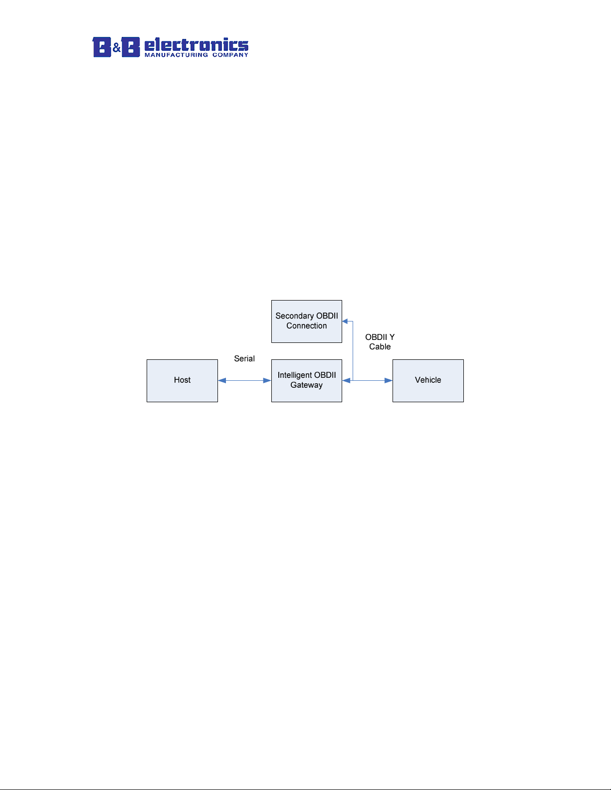
Overview
The OBDII Streamer is an OBDII to Serial gateway. The raw data, multiple PIDs per
parameter, and timing issues of the OBDII bus are abstracted from the host. The OBDII
Streamer allows a developer to quickly access data from the vehicle without having
knowledge of the OBDII bus.
The OBDII Streamer is intended to be permanently installed in a vehicle. Coupled with
B&B Electronics OBDII Y-Cable the OBDII Streamer will immediately disconnect from
the OBDII bus when another scan tool is connected to the bus.
The maximum update rate of data from the OBDII bus is 20Hz. Each parameter enabled
constitutes one update from the vehicle. The update rate from the vehicle is not linked to
any messages from the host. The host will be able to request data from the OBDII
Streamer immediately after the previous response, but the OBDII data will be limited to
an update rate of 20Hz.
Vehicle status parameters, such as the MIL, Fuel Level, and Battery Voltage, will be
updated from the vehicle no faster than once every 2 seconds. The vehicle parameter
DTC’s will be updated from the vehicle no faster than once every minute. The host can
request these parameters from the OBDII Streamer at any rate desired.
Startup Procedure
When the OBDII Streamer is powered on a CRC check will be performed to verify that
the code on the device is valid. This will take approximately 10 seconds and during that
time the device is unable to respond to commands.
On initial power on the OBDII Streamer will attempt to detect the vehicle type and
supported parameters. This process can take up to 1 minute. During this time the OBDII
Streamer will be responsive to host requests. If the OBDII Streamer has detected a
vehicle type and supported parameters it will not attempt to detect them again, even if the
vehicle type and supported parameters have changed.
While the host is detecting the vehicle’s information most messages will be responded to
with the following response.
0x01 0x01 0x81 0x00 0x83 //Vehicle Not (Yet) Detected Message
Page 6/49
Page 7

OBDII Streamer Command & Response
V2.11
The following commands will respond normally during startup:
- READ_MODEL_NUMBER
- FIRMWARE_VERSION
- READ_SERIAL
- UPGRADE_FIRMWARE
When the OBDII Streamer has finished the initialization sequence it will send a
DEVICE_CONFIGURED message.
After this message is received the OBDII Streamer will be ready for communications.
Non-Volatile Storage
Most configuration settings and parameters are stored in non-volatile memory and do not
have to be reconfigured on startup. The following settings and parameters are saved in
non-volatile memory.
Serial Number
BAUD
OEM_ID
Model Number
VIN
Firmware/EEPROM Versions
Vehicle information (OBDII Bus and Available Parameters)
Enabled/Disabled Parameters
Update Modes (Time and Threshold based)
Transferring to a New Vehicle
The OBDII Streamer stores all vehicle information in non-volatile memory. To improve
startup times in the event of a power loss all parameters will be reloaded from memory.
If the OBDII Streamer is removed from one vehicle and installed in another, the OBDII
Streamer must be forced to detect. On startup the previous vehicle’s data will be loaded.
The behavior of an OBDII Streamer will be unpredictable when connected to a vehicle
that is different than the vehicle detected. To force the OBDII Streamer to redetect
vehicle information send the REDETECT_VEHICLE command.
Ignition Detection
The vehicles J1962 diagnostic connector is always powered, even with the vehicle
ignition off. The OBDII Streamer detects the ignition status by analyzing data retrieved
over the OBDII bus. There are two methods used to determine ignition status.
First, the engine speed and vehicle speed are monitored from the vehicle. When engine
speed and vehicle speed are detected as zero for 2 minutes the OBDII Streamer will enter
Standby mode.
Page 7/49
Page 8

OBDII Streamer Command & Response
V2.11
Second, most vehicles stop responding to OBDII requests when the ignition is off. After
20 seconds of no responses from the vehicle the OBDII Streamer will enter Standby
mode.
The OBDII Streamer polls the vehicle for ignition status every two seconds. When the
ignition status changes from off to on the device will return to normal mode and will send
an ignition status message to the host.
Low Power Modes
Standby Mode:
During Standby Mode the vehicle is polled periodically to find out its ignition status.
Standby Mode will be the default mode used.
Standby Mode is entered within 20 seconds of communications loss.
Standby Mode is entered within 2 minutes of 0 RPM and 0 Vehicle Speed
(Vehicle Speed was added as a condition because a hybrid vehicle can turn the
engine off and be running on the electric engine).
Standby Mode is exited within ten seconds after vehicle starts communicating
LDV Streamer remains partially responsive to some communications while in
Standby Mode.
Maximum Power Consumption: 0.42W.
Maximum Time from power-on to valid vehicle data: fifteen seconds when
vehicle is running.
When the vehicle’s battery voltage is below 12.6V the vehicle is no longer polled
to save more power. When the ignition is turned on the alternator will increase
the voltage above 12.6V and the maximum time to normal running mode will be
met.
Special Cases:
First Time Installation: The OBDII Streamer does not enter any low power
modes until it has been installed on a vehicle and has detected the supported
parameters.
Firmware updates: After a firmware update, the OBDII Streamer will go into
the appropriate power state for normal operation.
Unintentional Reset (Battery removal, brownout, etc.): After an unintentional
reset, the OBDII Streamer will go into the appropriate power state for normal
operation.
Move to Different Vehicle:
• The LDV Streamer should remain in the appropriate low power mode
until it has been determined that the engine is running.
• The LDV Streamer requires a REDETECT_VEHICLE command to
work properly after moving to a different vehicle.
Page 8/49
Page 9

OBDII Streamer Command & Response
V2.11
Settings
The following variables make up all of the settings that should be known or changed
when using the OBDII Streamer.
Overview
The OBDII Streamer is capable of transmitting messages to the host automatically based
on user set criteria. By default these messages are disabled.
Time Based Updates
“Time Based” updates will provide an update of all enabled parameters at every time
interval specified by the user.
Time based updating will work simultaneously with “Threshold Based” updating and “As
Requested” updating.
Threshold Based Updates
“Threshold Based Updating” will send an update to the host whenever an enabled
parameter with threshold checking enabled exceeds the threshold.
“Threshold Based” updating will work simultaneously with “Time Based” updating and
“As Requested” updating.
As Requested Updates
“As Requested” update mode allows the host to request a single parameter, or all
parameters, at any time and receive a snapshot of the parameter values.
“As Requested” update mode is not an exclusive mode. This means that “Time Based”,
and “Threshold Based” update modes can be enabled and parameters can still be
requested at any time.
BAUD
The BAUD rate setting is only applicable to the RS-232 serial version of the OBDII
Streamer. The BAUD rate will default to 115.2kbps.
OEM_ID
The OEM_ID field is available for the customer to program as they choose. This field is
10 bytes long and defaults to “LDV_OEM_ID”.
An example use of this field is to key the software to a particular piece of hardware.
Page 9/49
Page 10

OBDII Streamer Command & Response
V2.11
Update Mode
On initial power up all update modes are disabled. In order to use any of the update
modes listed below they must be configured and enabled using the
SET_UPDATE_MODE and CHANGE_PARAMETER_THRESHOLD commands.
- Time Based
- Threshold Based
In order to receive automatic messages based on time or threshold the
CHANGE_PARAMETER_THRESHOLD command must be sent for each parameter.
Enable_Parameters
By default, all supported parameters will be updated from the vehicle. The
Enable_Parameters command can be sent in order to enable updates on only the
supported parameters.
Setting the Enable_Parameters command is desirable in some cases to increase the
parameter update rate. The update rate for each parameter is equal to the total update rate
from the vehicle divided by the number of enabled parameters.
The update rate from the vehicle is fixed and varies from vehicle to vehicle, but will not
exceed 20Hz.
Page 10/49
Page 11

OBDII Streamer Command & Response
V2.11
Parameters
This list matches a parameter with its identifier.
ID Parameter Return Size Units Range
0x00 Vehicle Speed 2 Bytes MPH 0 to 160
0x01 Engine Speed 2 Bytes RPM 0 to 16384
0x02 Throttle Position 2 Bytes % 0 to 100
0x03 Odometer 4 Bytes Miles 0 to 999,992
0x04 Fuel Level 2 Bytes % 0 to 100
0x07 Engine Coolant Temp 2 Bytes ºF -40 to 983
0x08 Ignition Status 2 Bytes On/Off On/Off
0x09 MIL Status 2 Bytes On/Off On/Off
0x0C Fuel Rate 2 Bytes Gallons per Hour 0 to 29.99
0x0D Battery Voltage 2 Bytes Volts 0 to 18
0x0E PTO Status 2 Bytes On/Off On/Off
0x0F Seatbelt Fastened 2 Bytes Yes/No N/A
0x10 Misfire Monitor 2 Bytes Status N/A
0x11 Fuel System Monitor 2 Bytes Status N/A
0x12 Comprehensive Component
Monitor
0x13 Catalyst Monitor 2 Bytes Status N/A
0x14 Heated Catalyst Monitor 2 Bytes Status N/A
0x15 Evaporative System Monitor 2 Bytes Status N/A
0x16 Secondary Air System Monitor 2 Bytes Status N/A
0x17 A/C System Refrigerant Monitor 2 Bytes Status N/A
0x18 Oxygen Sensor Monitor 2 Bytes Status N/A
0x19 Oxygen Sensor Heater Monitor 2 Bytes Status N/A
0x1A EGR System Monitor 2 Bytes Status N/A
0x1B Brake Switch Status 2 Bytes Pressed/Not
0x22 Trip Odometer 4 Bytes Miles 0 to 999,992
0x23 Trip Fuel Consumption 4 Bytes Gallons 0 to 999,992
2 Bytes Status N/A
N/A
Pressed
Page 11/49
Page 12

OBDII Streamer Command & Response
V2.11
0x00 Vehicle Speed
Scaling Equation:
Result = Returned Data * 1 / 410
Units: Miles per hour
EX: Return Data = 26650
Result = 26650 * 1 / 410
Result = 65 Miles per hour
0x01 Engine Speed
Scaling Equation:
Result = Returned Data * 1 / 4
Units: Revolutions per Minute
EX: Return Data = 12000
Result = 12000 * 1 / 4
Result = 3000 Revolutions per Minute
0x02 Throttle Position
Scaling Equation:
Result = Returned Data * 1 / 655
Units: %
EX: Return Data = 12000
Result = 12000 * 1 / 655
Result = 18.32 % Throttle Pedal Position
0x03 Odometer
Scaling Equation:
Result = Returned Data * 1 / 1
Units: Miles
EX: Return Data = 58,125
Result = 58,125 * 1 / 1
Result = 58,125 Miles
0x04 Fuel Level
Scaling Equation:
Result = Returned Data * 1 / 655
Units: %
EX: Return Data = 23578
Result = 23578 * 1 / 655
Result = 35.99 %
Page 12/49
Page 13

OBDII Streamer Command & Response
V2.11
0x07 Engine Coolant Temp
Scaling Equation:
Result = (Returned Data * 1 / 64) - 40
Units: ºF
EX: Return Data = 14080
Result = (14080 * 1 / 64) - 40
Result = 180ºF
0x08 Ignition Status
Return Value of 1 = Ignition Off
Return Value of 0 = Ignition On
0x09 MIL Status
Return Value of 1 = MIL Off
Return Value of 0 = MIL On
0x0C Fuel Rate
Scaling Equation:
Result = Returned Data * 1 / 2185
Units: Gallons per Hour
EX: Return Data = 25650
Result = 25650 * 1 / 2185
Result = 11.74 Gallons per Hour
0x0D Battery Voltage
Scaling Equation:
Result = Returned Data * 1 / 3641
Units: Volts
EX: Return Data = 45650
Result = 45650 * 1 / 3641
Result = 12.538 Volts
0x0E PTO Status
Return Value of 1 = PTO Off
Return Value of 0 = PTO On
0x0F Seatbelt Fastened
Return Value of 1 = Seat Belt not Fastened
Return Value of 0 = Seat Belt Fastened
Page 13/49
Page 14

OBDII Streamer Command & Response
V2.11
0x10 — 0x1A Monitors
Return Value of 1 = Monitor Not Complete
Return Value of 0 = Monitor Complete
0x1B Brake Switch Status
Return Value of 1 = Brake Switch Off
Return Value of 0 = Brake Switch On
0x22 Trip Odometer
Scaling Equation:
Result = Returned Data * 1 / 10
Units: Miles
EX: Return Data = 58,125
Result = 58,125 * 1 / 10
Result = 5,812.5 Miles
0x23 Trip Fuel Consumption
Scaling Equation:
Result = Returned Data * 1 / 128
Units: Gallons
EX: Return Data = 8,128
Result = 8128 * 1 / 128
Result = 63.5 Gallons
NOTE: It is basically returned in Ounces.
Page 14/49
Page 15

OBDII Streamer Command & Response
V2.11
Commands
0x02 – READ_MODEL_NUMBER
Description:
This command will return the model number as an alpha-numeric ASCII string.
The following model numbers can be returned depending on the type of Streamer used.
LDVDSV2-S RS-232 OBDII Streamer
Command to Send:
0x01 0x01 0x02 0x00 0x04
Response:
0x01 0x01 0x82 DL MODEL CS
Field Description:
MODEL Variable length model number up to 16 characters long. This field
is returned as ASCII characters.
DL Data Length (Length of model number)
CS Summation checksum
Example:
TX: 0x01 0x01 0x02 0x00 0x04
RX: 0x01 0x01 0x82 0x09 0x4C 0x44 0x56 0x44 0x53 0x56 0x32 0x2D 0x53 0x12
The model number returned is LDVDSV2-S.
Page 15/49
Page 16

OBDII Streamer Command & Response
V2.11
0x03 – GET_COMPONENT_VERSIONS
Description:
This command will return the version numbers for all updatable components in the
device.
Command to Send:
0x01 0x01 0x03 0x00 0x05
Response:
0x01 0x01 0x83 0x0F
SYS3 BL1 BL2 BL3 CS
Field Descriptions:
SW1-SW3 Software version digits 1-3
HW1-HW3 Hardware version digits 1-3
DB1-DB3 Database version digits 1-3
SYS1-SYS3 System manager version digits 1-3
BL1-BL3 Bootloader version digits 1-3
CS Summation checksum
Example:
TX:
0x01 0x01 0x03 0x00 0x05
RX:
0x01 0x01 0x83 0x0F 0x02 0x00 0x06 0x02 0x00 0x03 0x01 0x08 0x00
0x02 0x00 0x04 0x02 0x00 0x01 0xB3
The version numbers returned as hexadecimal are:
Software version
Hardware version
Database version
System manager version
Bootloader version
SW1 SW2 SW3 HW1 HW2 HW3 DB1 DB2 DB3 SYS1 SYS2
0x02 0x00 0x0A = 2.0.10
0x02 0x00 0x03 = 2.0.3
0x01 0x08 0x00 = 1.8.0
0x02 0x00 0x04 = 2.0.4
0x02 0x00 0x01 = 2.0.1
Page 16/49
Page 17

OBDII Streamer Command & Response
V2.11
0x04 – OBDII_FIRMWARE_VERSION (Obsolete)
Description:
This command is no longer supported as of version 2.
0x05 – FIRMWARE_VERSION (Deprecated)
Description:
[Command 0x03 – GET_COMPONENT_VERSIONS should be used instead of this
command.]
This command will return the version number of the software component.
Command to Send:
0x01 0x01 0x05 0x00 0x07
Response:
0x01 0x01 0x85 0x03 VER1 VER2 VER3 CS
Field Description:
VER1 Hex version number digit 1
VER2 Hex version number digit 2
VER3 Hex version number digit 3
CS Summation checksum
Example:
TX: 0x01 0x01 0x05 0x00 0x07
RX: 0x01 0x01 0x85 0x03 0x01 0x00 0x01 0x8C
The version number returned is 0x01 0x00 0x01 = 1.0.1
Page 17/49
Page 18

OBDII Streamer Command & Response
V2.11
0x06 – DATABASE _VERSION (Deprecated)
Description:
[Command 0x03 – GET_COMPONENT_VERSIONS should be used instead of this
command.]
This command will return the version number of the database component.
Command to Send:
0x01 0x01 0x06 0x00 0x08
Response:
0x01 0x01 0x86 0x03 VER1 VER2 VER3 CS
Field Description:
VER1 Hex version number digit 1
VER2 Hex version number digit 2
VER3 Hex version number digit 3
CS Summation checksum
Example:
TX: 0x01 0x01 0x06 0x00 0x08
RX: 0x01 0x01 0x86 0x03 0x01 0x00 0x01 0x8D
The version number returned is 0x01 0x00 0x01 = 1.0.1
Page 18/49
Page 19

OBDII Streamer Command & Response
V2.11
0x07 – READ_SERIAL_NUMBER
Description:
This command will return the ten digit hardware serial number. The serial number is
programmed at manufacturing time and should match the serial number sticker on the
side of the hardware.
Command to Send:
0x01 0x01 0x07 0x00 0x09
Response:
0x01 0x01 0x87 0x0A SERIAL CS
Field Description:
SERIAL 10 digit serial number returned as numeric ASCII
characters.
CS Summation checksum
Example:
TX: 0x01 0x01 0x07 0x00 0x09
RX: 0x01 0x01 0x87 0x0A 0x31 0x35 0x33 0x31 0x38 0x32 0x36 0x34 0x33 0x37 0x9B
The serial number returned is 1531826437.
Page 19/49
Page 20

OBDII Streamer Command & Response
V2.11
0x09 – CONFIG_OEM_ID
Description:
This command will set or read the 10 digit OEM ID. Each digit of the OEM_ID is 1 byte
and can be any possible value. The command to write the OEM ID always expects 10
digits/values and will give an error with any values less than or greater than 10.
The OEM_ID will be saved in non-volatile memory.
The first byte of the data field indicates if the OEM_ID will be read or written.
0x00 = read
0x01 = write
Command to send to read the OEM_ID:
0x01 0x01 0x09 0x01 0x00 0x0C
Response:
0x01 0x01 0x89 0x0B 0x00 OEM_ID CS
Command to send to write the OEM_ID:
0x01 0x01 0x09 DL 0x01 OEM_ID CS
Response:
0x01 0x01 0x89 0x0B 0x01 OEM_ID CS
Field Description:
OEM_ID 10 digit OEM_ID
DL Data field length
CS Summation checksum
Example: Set the OEM_ID
TX: 0x01 0x01 0x09 0x0B 0x01 0x01 0x35 0x73 0x99 0x24 0x72 0xF3 0x17 0xAC
0xBB 0x60
RX: 0x01 0x01 0x89 0x0B 0x01 0x01 0x35 0x73 0x99 0x24 0x72 0xF3 0x17 0xAC
0xBB 0xE0
Example: Read the OEM_ID
TX: 0x01 0x01 0x09 0x01 0x00 0x0C
RX:
0x01 0x01 0x89 0x0B 0x00 0x01 0x35 0x73 0x99 0x24 0x72 0xF3 0x17 0xAC 0xBB
0xDF
Page 20/49
Page 21

OBDII Streamer Command & Response
V2.11
0x15 – SERIAL_BAUD
Description:
This command will read or write RS-232 Baud Rate settings.
The configuration data is stored in non-volatile memory and will be loaded on system
power-on.
Command to Send:
0x01 0x01 0x15 0x03 RD/WR BAUD 0x01 CS
Response:
0x01 0x01 0x95 0x03 RD/WR BAUD 0x01 CS
Field Description:
RD/WR This indicates if the message will be a read or a write.
0x00 = read 0x01 = write
Note: If the request message is a configuration read then
the BAUD and STATUSMSG fields should not be included
in the request message, and the data length will be 1 byte.
BAUD BAUD setting
0x00 = 9600kbps 0x01 = 19200kbps
0x02 = 38400kbps 0x03 = 56000kbps
0x04 = 115200kbps (Default)
CS Summation checksum
Example: Baud = 19200kbps
TX: 0x01 0x01 0x15 0x03 0x01 0x01 0x01 0x1D
RX: 0x01 0x01 0x95 0x03 0x01 0x01 0x01 0x9D
Page 21/49
Page 22

OBDII Streamer Command & Response
V2.11
0x20 – GET_SUPPORTED_PARAMETERS
Description:
This command will return an identifier byte for each supported parameter.
Only supported parameters will be requested from the vehicle. Parameter values reported
for an unsupported parameter are invalid. Supported parameters are available after the
vehicle has been detected.
Command to Send:
0x01 0x01 0x20 0x00 0x22
Response:
0x01 0x01 0xA0 DL SUPPORTED_PARAMETERS CS
Field Description:
DL Data Length Byte
SUPPORTED_PARAMETERS Variable length data field containing one byte for
each supported parameter.
CS Summation checksum
Example:
TX:
0x01 0x01 0x20 0x00 0x22
RX:
0x01 0x01 0xA0 0x06 0x00 0x02 0x03 0x08 0x09 0x11 0xCF
The supported parameters in this example are:
0x00 – Vehicle Speed
0x02 – Throttle Position
0x03 – Odometer
0x08 – Ignition Status
0x09 – MIL Status
0x11 – Fuel System Monitor
Page 22/49
Page 23

OBDII Streamer Command & Response
V2.11
0x21 – ENABLE_PARAMETERS
Description:
This command will enable or disable only the specified parameters to be updated from
the vehicle. If parameters are enabled that are not supported by the vehicle the OBDII
Streamer will send a response indicating which parameters are not supported.
By default all supported parameters are enabled and queried from the vehicle. Because
the update rate of the vehicle is limited to a maximum of 20 Hz, it may be desirable to
disable some parameters to get better update rates on parameters of interest.
Command to Send:
0x01 0x01 0x21 DL RD/WR ENABLE/DISABLE PARAMETER_LIST CS
Response to write:
0x01 0x01 0xA1 DL 0x01 ENABLE/DISABLE NOT_SUPP CS
Response to read:
0x01 0x01 0xA1 DL 0x00 PARAMETER_LIST CS
Field Description:
DL Data Length Byte
RD/WR This indicates if the message will be a read or a write.
0x00 = read
0x01 = write
Note: If the request message is a configuration read then
the ENABLE/DISABLE and PARAMETER_LIST fields
should not be included, and the data length will be 1 byte.
ENABLE/DISABLE This field in 1 byte that indicates if the parameters specified
in PARAMETER_LIST should be enabled or disabled.
The state of the parameters not specified in the
PARAMETER_LIST field will not change.
0x00 = Enable specified parameters
0x01 = Disable specified parameters
This field will not be present in a response to a read
enabled parameters command.
PARAMETER_LIST Variable length data field containing one byte for each
parameter to be enabled. Each byte corresponds to a
parameter ID. This should not be included in the request
message if reading the ENABLE_PARAMETERS data.
Page 23/49
Page 24

OBDII Streamer Command & Response
V2.11
If one byte value 0xFF is used for PARAMETER_LIST
then all the supported parameters will be either enabled or
disabled according to the ENABLE/DISABLE byte.
NOT_SUPP Variable length field containing one byte for each
parameter that was requested to be enabled/disabled, but is
not supported by the vehicle. This may be a zero length
field.
CS Summation checksum
Example 1: Enable Parameters
TX: 0x01 0x01 0x21 0x04 0x01 0x00 0x02 0x03 0x2D
RX: 0x01 0x01 0xA1 0x02 0x01 0x00 0xA6
The command sent requests Throttle Position and Odometer to be enabled. All
parameters that were requested to be enabled are supported by the vehicle.
Example 2: Enable Parameters
TX: 0x01 0x01 0x21 0x04 0x01 0x00 0x02 0x03 0x2D
RX: 0x01 0x01 0xA1 0x03 0x01 0x00 0x02 0xA9
The command sent requests Throttle Position and Odometer to be enabled. All
parameters that were requested to be enabled are supported by the vehicle except for
Throttle Position.
Example 3: Read Enabled Parameters
TX: 0x01 0x01 0x21 0x01 0x00 0x24
RX: 0x01 0x01 0xA1 0x03 0x00 0x00 0x01 0xA7
The command sent requests a list of all enabled parameters. Vehicle Speed and Engine
Speed are enabled and listed in the response.
Example 4: Disable Parameters
TX: 0x01 0x01 0x21 0x04 0x01 0x01 0x02 0x03 0x2E
RX: 0x01 0x01 0xA1 0x03 0x01 0x01 0x02 0xAA
The command sent requests that Throttle position and Odometer be disabled. The
response indicates that all the requested parameters except Throttle position were
supported and have been disabled.
Note: Engine Speed and Vehicle Speed cannot be disabled.
Page 24/49
Page 25

OBDII Streamer Command & Response
V2.11
0x22 – GET_PARAMETER
Description:
This command will return the current value for the requested parameter. Since the most
current parameter’s results are stored in the OBDII Streamer the response delay will be
very short.
Command to Send:
0x01 0x01 0x22 DL PARAMETER_ID CS
Response:
0x01 0x01 0xA2 DL PARAMETER_DATA CS
Field Description:
DL Data Length Byte
PARAMETER_ID Variable length data field containing one byte for each parameter
requested. Each byte corresponds to a parameter ID.
Multiple parameters can be specified in the PARAMETER_ID field, or
0xFF can be specified to request all enabled parameters.
A maximum of 11 parameters can be specified in one message. If 0xFF is
sent to request all enabled parameters then the response may be broken
into multiple responses depending on the number of enabled parameters.
PARAMETER_DATA
The PARAMETER_DATA field is a variable length data field that
contains both the requested parameter(s) identifier and the parameter data.
All parameter identifiers are one byte long, and parameter data is variable
length. The format of the data field is a repeating pattern of parameter
identifier1, Data1, parameter identifier2, Data2,.. etc.
CS Summation checksum
Example:
TX: 0x01 0x01 0x22 0x03 0x01 0x02 0x03 0x2D
RX: 0x01 0x01 0xA2 0x09 0x01 0x01 0x23 0x02 0x98 0x76 0x03 0x55 0x66 0x77 0x88
0x9F
The breakdown of the response is:
Parameter 0x01: Data = 0x0123
Parameter 0x02: Data = 0x9876
Page 25/49
Page 26

OBDII Streamer Command & Response
V2.11
Parameter 0x03: Data = 0x55667788 (some parameters are 4 bytes of data, including
odometer)
Page 26/49
Page 27

OBDII Streamer Command & Response
V2.11
0x23 – GET_VEHICLE_STATUS
Description:
This command will return the status of the vehicle ignition and the secondary OBDII tool
status.
Command to Send:
0x01 0x01 0x23 0x00 0x25
Response:
0x01 0x01 0xA3 0x02 IGNITION OBDII_STAT CS
Field Description:
IGNITION This is a 1 byte field that indicates the status of the vehicle
ignition.
0x00 = Ignition OFF
0x01 = Ignition ON
Note: The methods used to determine the ignition status actually
detect when the OBDII bus is responding to requests, and not the
ignition status. It is possible that some vehicles will continue to
respond while the ignition is off. All vehicles are required to
communicate when the key is in the on position and the engine is
not running.
OBDII_STAT This is a 1 byte field that indicates if a second scan tool is
connected to the OBDII port.
0x00 = No Tool
0x01 = Tool Connected
0xFF = Scan tool status unknown (device in standby mode)
CS Summation checksum
Example:
TX:
0x01 0x01 0x23 0x00 0x25
RX:
0x01 0x01 0xA3 0x02 0x01 0x00 0xA8
The response indicates that the ignition is on and no secondary tool is connected.
Page 27/49
Page 28

OBDII Streamer Command & Response
V2.11
0x24 – REDETECT_VEHICLE
Description:
This command will force all detected vehicle information to be redetected. The
REDETECT_VEHICLE command should only be required if the Streamer is removed
from one vehicle and moved to another or after exiting Bypass mode to ensure correct
vehicle-specific data is stored in non-volatile memory. Issuance of this command will
cause Streamer to wake up if it was in Standby mode.
Command to Send:
0x01 0x01 0x24 0x00 0x26
Response:
0x01 0x01 0xA4 0x00 0xA6
This response will be transmitted immediately. When the detection process is finished
the DEVICE_CONFIGURED message will be transmitted.
Example:
TX: 0x01 0x01 0x24 0x00 0x26
RX: 0x01 0x01 0xA4 0x00 0xA6 -Received immediately
The configuration time may take up to 1 minute to complete. Any requests during this
time will be responded to with a VEHICLE_NOT_DETECTED message.
RX: 0x01 0x01 0x80 0x00 0x82 -DEVICE_CONFIGURED message
Page 28/49
Page 29

OBDII Streamer Command & Response
V2.11
0x25 – GET_VEHICLE_INFO
Description:
The GET_VEHICLE_INFO command will return the VIN, OBDII protocol being used,
or any DTCs set. In Standby mode, requesting VIN and OBDII protocol returns last
saved values read from non-volatile memory while DTCs request will return error 0x0F –
command parameter not supported.
Command to Send:
0x01 0x01 0x25 0x01 INFO_TYPE CS
Response:
0x01 0x01 0xA5 DL INFO_TYPE INFO_RESPONSE CS
Field Description:
DL Data Length Byte
INFO_TYPE The INFO_TYPE field specifies the return data.
0x00 = VIN
0x01 = OBDII Protocol
0x02 = Diagnostic Trouble Codes (DTCs)
INFO_RESPONSE This is a variable length response. This field is specified by
INFO_TYPE and will be either the VIN or the OBDII Protocol.
INFO_TYPE = 0 = VIN
The INFO_RESPONSE is a 17 character VIN.
INFO_TYPE = 1 = OBDII Protocol
INFO_RESPONSE is a 1 digit number that defines the
OBDII protocol detected.
0 = None
1 = J1850VPW
2 = J1850PWM
3 = ISO9141-2
5 = KWP2000
6 = CAN 11 bit
7 = CAN 29 bit at 500 kbps
12 = CAN 29 bit at 250 kbps
INFO_TYPE = 2 = DTCs
The INFO_RESPONSE is a variable length field
containing DTCs. The DTCs will be ASCII values and
each code will be 5 digits long.
Only confirmed DTCs are reported.
Page 29/49
Page 30

OBDII Streamer Command & Response
V2.11
CS Summation Checksum
Example
This command requests all DTCs from the vehicle.
TX: 0x01 0x01 0x25 0x01 0x02 0x2A
RX:
0x01 0x01 0xA5 0x0B 0x02 0x50 0x30 0x34 0x33 0x30 0x50 0x30 0x32 0x35 0x30
0xE2
The above response indicates that two DTCs are present on the vehicle.
Page 30/49
Page 31

OBDII Streamer Command & Response
V2.11
0x30 – SET_TIME_UPDATES
Description:
This command will setup the periodic update settings for a single parameter.
Note that when a timed update message is sent to the host the message will be packaged
in the same format as command 0x22 but with a new control byte. Time based update
messages will use control byte 0xC0.
The SET_UPDATE_MODE command must be sent to enable all parameters configured
for time based updates to be sent.
Command to Send:
0x01 0x01 0x30 0x04 PID SETTINGS TVALUE CS
Response:
0x01 0x01 0xB0 0x04 PID SETTINGS TVALUE CS
Field Description:
PID This field is a 1 byte PID. Use this field to select the PID that will
be configured.
SETTINGS Settings
Bit 0 - This bit will enable or disable periodic updates for the
selected parameter.
0x00 = Disabled
0x01 = Enabled
If disabling a parameter the TVALUE byte must be sent, but can
be set to any value since it will be ignored.
TVALUE Time Value
This field is two bytes long and will configure the period between
updates. The resolution of the timer is 50mS.
Timeout Range = 50mS to 54.6 minutes
Period = 50mS * TVALUE
Note that if TVALUE of 0 is set the parameter will update once
every 50mS.
CS Summation checksum
Page 31/49
Page 32

OBDII Streamer Command & Response
V2.11
Example:
This command sets up the vehicle speed PID to be transmitted every 250mS.
TX:
0x01 0x01 0x30 0x04 0x00 0x01 0x00 0x05 0x3C
RX:
0x01 0x01 0xB0 0x04 0x00 0x01 0x00 0x05 0xBC
250mS delay
RX:
0x01 0x01 0xC0 0x03 0x00 0x01 0x23 0xE9
The above response is received 250 mS after the Time Updating was setup and indicates
that the vehicle speed has an un-scaled value of 0x0123.
Page 32/49
Page 33

OBDII Streamer Command & Response
V2.11
0x31 – SET_THRESHOLD_UPDATES
Description:
This command will setup the threshold triggered messages for a single parameter.
Note that when a threshold is tripped and a message is sent to the host the message will
be packaged in the same format as command 0x22 but with a new control byte.
Threshold based update messages will use control byte 0xC1.
The SET_UPDATE_MODE command must be sent to enable all parameters configured
for threshold based updates to be sent.
Command to Send:
0x01 0x01 0x31 0x04 PID SETTINGS TVALUE CS
Response:
0x01 0x01 0xB1 0x04 PID SETTINGS TVALUE CS
Field Description:
PID This field is a 1 byte PID. Use this field to select the PID that will
be configured.
SETTINGS Threshold Settings
Bit 0 - This bit will enable or disable threshold updates for the
selected parameter.
0x00 = Disabled
0x01 = Enabled
If disabling a parameter the TVALUE byte must be sent, but can
be set to any value since it will be ignored.
Bit 1 – This bit specifies if trigger level is greater than or less than
the TVALUE.
0 = Send a message when the parameter > TVALUE
1 = Send a message when the parameter < TVALUE
The TVALUE is compared to the value returned by the
device before the parameter scaling is applied. If the
parameter being configured has 2 states set the threshold to
(< 1) or (> 0). If the parameter being configured is a 4 byte
parameter the TVALUE will be compared to all 4 byte of
the value.
Page 33/49
Page 34

OBDII Streamer Command & Response
V2.11
TVALUE Threshold Value
This field is two bytes long and will configure the threshold value
used to determine when to send a message. The value in this field
should be passed to the Intelligent OBDII Streamer using reverse
scaling.
CS Summation checksum
Example:
This command sets up the vehicle speed PID to be transmitted when the vehicle speed is
greater than 40 MPH.
TX:
0x01 0x01 0x31 0x04 0x00 0x01 0x40 0x10 0x88
RX:
0x01 0x01 0xB1 0x04 0x00 0x01 0x40 0x10 0x08
Threshold Value = 0x4010 = 16400
16400 / 410 = 40MPH
Unknown Delay. The following message will be received every time the parameter is
updated AND the vehicle speed parameter is over 40 MPH.
RX:
0x01 0x01 0xC1 0x03 0x00 VEHICLE_SPEED CS
0x32 – SET_FULLSPEED_UPDATES (Obsolete)
Description:
This command is no longer supported as of Streamer version 2.
Page 34/49
Page 35

OBDII Streamer Command & Response
V2.11
0x33 – READ_PARAMETER_UPDATE_MODES
Description:
This command will return the update mode settings for the specified parameter.
Command to Send:
0x01 0x01 0x33 0x01 PID CS
Response:
0x01 0x01 0xB3 0x06 PID TIME THRESHOLD TSETTINGS CS
Field Description:
PID This field is a 1 byte PID.
TIME This field is two bytes and is reports the period set for the selected
parameter.
Period = TIME * .05 seconds.
THRESHOLD This field is two bytes and reports the threshold set for the selected
parameter.
TSETTINGS Threshold Settings
Bit 0 – Time updates Enabled
0x00 = Disabled
0x01 = Enabled
Bit 1 – Threshold updates Enabled
0x00 = Disabled
0x01 = Enabled
Bit 2 – Obsolete, always returned as 0x01
Bit 3 – This bit specifies if a message will be sent when the
parameter data is above the threshold value or below.
0 = Send a message when the parameter > TVALUE
1 = Send a message when the parameter < TVALUE
CS Summation checksum
Example:
This command requests the settings for the vehicle speed parameter.
Page 35/49
Page 36

OBDII Streamer Command & Response
V2.11
TX:
0x01 0x01 0x33 0x01 0x01 0x37
RX:
0x01 0x01 0xB3 0x06 0x01 0x00 0x05 0x01 0x23 0x01 0xE6
The above response indicates that time based updates are the only enabled updates and a
periodic message will be sent every 250 mS.
Page 36/49
Page 37

OBDII Streamer Command & Response
V2.11
0x35 – SET_UPDATE_MODE
Description:
This command enables or disables the different types of update modes. All update modes
can be enabled simultaneously.
This command is a general enable for all PIDs configured for a particular update mode.
For example, if a SET_UPDATE_MODE command is sent to enable time based
updating, all parameters configured for time based updating will be enabled and data will
start to be transmitted at the user selected intervals.
This configuration data will NOT be saved to non-volatile memory and must be set in
order to receive update messages. “As Requested” update mode does not require the
SET_UPDATE_MODE message to be sent before parameters can be requested.
Command to Send:
0x01 0x01 0x35 0x02 MODE ENABLE CS
Response:
0x01 0x01 0xB5 0x02 MODE ENABLE CS
Note: If the vehicle is turned off when this command is sent, the response will be an
Ignition Off Status Message instead of the above response, and the mode will NOT be
enabled.
Field Description:
MODE The MODE byte selects the update mode.
0x00 = Time Based
0x01 = Threshold Based
0xFF = All Modes
ENABLE The ENABLE byte enables or disables the specified MODE.
0x00 = Disable
0x01 = Enable
CS Summation checksum
Example:
TX: 0x01 0x01 0x35 0x02 0x01 0x01 0x3B
RX: 0x01 0x01 0xB5 0x02 0x01 0x01 0xBB
This command enables threshold based updating for all parameters configured with a
threshold and enabled.
Page 37/49
Page 38

OBDII Streamer Command & Response
V2.11
0x57 – UPDATE_COMPONENT
Description:
This command will allow the upgradeable components in the OBDII Streamer to be
updated in the field. The V2 Streamer firmware update protocol is intentionally different
from the V1.x streamers to avoid accidental programming of v1.x streamers (or vice
versa) in situations where a customer may have mixed streamer populations. The
streamer expects to receive the images in Motorola S-record format and in Intel HEX
format.
The update of the System Manager can occur either before or after the other components
however. If both the FPGA hardware/firmware image and the OBDII database both need
to be upgraded, the FPGA hardware/firmware image should be updated first.
1) FPGA Firmware/Hardware image
2) OBDII database
3) System Manager
4) Bootloader
Once successfully programmed, the boot loader will reset and run the new firmware.
NOTE:
A minimum of twenty five seconds is required between each file update to allow the
firmware to reset and run. The Streamer will not be responsive to host commands during
this time.
In the event of an incomplete system manager program for any reason, the hardware will
remain in the boot loader.
The Bootloader will validate system manager image stored in non-volatile memory. If the
image is valid Bootloader will pass control to system manager. Otherwise hardware will
remain in boot load mode.
The only host command device handles in boot load mode is UPDATE_COMPONENT
command with component parameter set to “System manager”. Error message with error
code 0x0B “System manager image is invalid. Update required” will be sent in response
to any other command.
Once successfully started System manager will validate FPGA and Database images
stored in non-volatile memory. If the images are valid then FPGA image will be started.
Otherwise system manager will enter component update wait mode. The only host
commands device will handle in this mode is UPDATE_COMPONENT command. Error
messages with error code 0x0C “FPGA image is invalid. Update required” or 0x0C
“Database image is invalid. Update required” will be sent in response to any other
command. Once FPGA is started it validates database image by software means and if the
Page 38/49
Page 39

OBDII Streamer Command & Response
V2.11
database version is not compatible with current firmware version then FPGA will shut
down and System manager will expect UPDATE_COMPONENT command.
The programming must always be successfully completed before moving on to the next
update file.
Host Command to Send:
0x01 0x01 0x57 0x01
COMP CS
Streamer ACK Response:
0x01 0x01 0xD7 0x00 0xD9
The Streamer will change from its programmed baud rate to the baud rates show in the
table below during the component update period. It will return to its previous baud rate
after completion of the update process and the streamer reinitializes itself (as detected by
the DEVICE_CONFIGURED spontaneous message.
Field Descriptions:
COMP Byte identifying which component is being updated:
0x01
0x02
0x03
0x04
FPGA Firmware
Database
System Manager
Bootloader
CS Summation checksum
Page 39/49
Page 40

OBDII Streamer Command & Response
T2
T1
UPDATE_COMPONENT ACK
See Chart
rate
V2.11
T1
Host
changes
baud
Host
Streamer
UPDATE_COMPONENT
Streamer
changes baud
rate
“@@&&” - ready
T3
“#”
Repeat this behavior until all records are sent
“!” - last S-record received
At the
original
baud
rate
Figure 1 Host Update Application and Streamer Interactions
New
commands
T4
Baud rate table for component updates
Streamer Option Baud Rate Change Notes
LDVDSV2-S 115,200 BPS The streamer host interface
changes to this baud rate as
LDVDSV2-1587 57600 BPS
shown in the diagram
above, when commanded to
begin a component update
command.
Page 40/49
Page 41

OBDII Streamer Command & Response
V2.11
Time Description Value (min-max)
T1 Streamer to host response time. Used by the
host software as a timeout value for host to
streamer communications timeouts. If the
streamer has not responded within the max
time value, the host will time out and terminate
the update.
T2 Time needed to switch to the default update
baud rate. Minimal guaranteed timeout is 5
seconds after which Streamer will send “ready”
string indicating readiness to receive S-records.
T3 Host to Streamer response time. Used by the
streamer as a timeout value for streamer to host
communications timeouts.
If no s-record is sent to the device after T3
timeout after the ready to receive “@@&&” is
sent then ready to receive will be sent 2
additional times.
Time out for the streamer to wait for the next
S-record to arrive after sending a ”#” indicating
that the streamer is ready for the next S-record.
T4 Time from acknowledgement of last S-record
received to restart of streamer.
If an error occurs then the streamer will send a two byte error code ASCII “E” followed
by a numeric digit.
Error Code Name Description Error Code
S-record timeout Streamer did not receive the complete S-
record in the allotted time period (T3).
S-record checksum S-record checksum did not match calculated
checksum. The streamer will expect the host
to resend the S-record otherwise it will time
out.
Hardware Failure Attempts to program the Flash device failed
multiple times. FPGA will not reboot.
Invalid S-record S-record format error, message corrupted E3
0-25 Seconds
5-35 seconds
0-45 seconds
0-45 seconds.
E0
E1
E2
Page 41/49
Page 42

OBDII Streamer Command & Response
V2.11
0x59 – UPGRADE_FIRMWARE (Obsolete)
Description:
This command has been replaced by the command 0x57 – UPDATE_COMPONENT.
0x60 – UPDATE_EEPROM (Obsolete)
Description:
This command has been replaced by the command 0x57 – UPDATE_COMPONENT.
0x61 – RESET_TRIP
Description:
This command resets the Trip Parameters ( Trip Odometer and Trip Fuel Consumption).
It will reset the trip parameters stored in EEPROM and RAM to Zero which signifies the
start of the trip.
Command to Send:
0x01 0x01 0x61 0x00 0x63
Response:
0x01 0x01 0xE1 0x00 0xE3
Page 42/49
Page 43

OBDII Streamer Command & Response
V2.11
Status Messages
Status messages are messages sent from the OBDII Streamer that weren’t expected by the
host. The status messages include error messages and vehicle status updates.
0x80 – DEVICE_CONFIGURED
Description:
A DEVICE_CONFIGURED message will be sent to the host when the OBDII Streamer
has finished detecting bus and supported parameters of the vehicle. When this message is
received the host may initiate communications.
Response:
0x01 0x01 0x80 0x00 0x82
0x81 – VEHICLE_NOT_DETECTED
Description:
The OBDII Streamer will respond to the host with a VEHICLE_NOT_DETECTED
message during startup. This command indicates that the OBDII connection is not fully
configured yet. Since configuration is automatic, no action needs to be taken to configure
the bus.
Startup configuration can take up to 1 minute after turning the key on for some vehicles.
When configuration is complete a DEVICE_CONFIGURED message will be sent to the
host.
Response:
0x01 0x01 0x81 0x00 0x83
Page 43/49
Page 44

OBDII Streamer Command & Response
V2.11
0xA3 – Ignition/OBDII Status
Command Byte: 0xA3
Description:
This message will be returned when the status of the vehicle ignition and the secondary
OBDII tool status changes. The format of this message is the same as found in the
Ignition Status command.
Response:
0x01 0x01 0xA3 0x02 IGNITION OBDII_STAT CS
Field Description:
IGNITION This is a 1 byte field that indicates the status of the vehicle
ignition.
0x00 = Ignition OFF
0x01 = Ignition ON
The method used to determine the ignition status detects when the
OBDII bus is responding to requests and when the RPM is not
zero.
The ignition will transition from off to on when vehicle or engine
speed is not zero.
It is possible that some vehicles will continue to respond while the
ignition is off. All vehicles are required to communicate when the
key is in the on position and the engine is not running.
OBDII_STAT This is a 1 byte field that indicates if a second scan tool is
connected to the OBDII port.
0x00 = No Tool
0x01 = Tool Connected
CS Summation checksum
Example:
RX:
0x01 0x01 0xA3 0x02 0x01 0x00 0xA8
This message indicates that the ignition is on and no secondary tool is connected.
Page 44/49
Page 45

OBDII Streamer Command & Response
V2.11
0xC0 – Time Based Update Message
Description:
This message will be sent for each enabled parameter after the specified interval. If
multiple parameters have time based updates enabled and timeout at the same interval the
responses will be combined.
Response:
0x01 0x01 0xC0 DL PARAMETER_DATA CS
Field Description:
DL Data Length Byte
PARAMETER_DATA The PARAMETER_DATA field is a variable length data
field that contains both the requested parameter identifiers and the
parameter data. All parameter data is two bytes long, and each parameter
identifier is one byte long. The format of the data field is a repeating
pattern of parameter identifier1, Data1, parameter identifier2, Data2,..
etc.
CS Summation checksum
Example:
RX:
0x01 0x01 0xC0 0x09 0x01 0x01 0x23 0x02 0x98 0x76 0x03 0x55 0x66 0x77 0x88
0xBD
The breakdown of the response is:
Parameter 0x01: Data = 0x0123
Parameter 0x02: Data = 0x9876
Parameter 0x03: Data = 0x55667788
Page 45/49
Page 46

OBDII Streamer Command & Response
V2.11
0xC1 – Threshold Based Update Message
Description:
This message will be sent when threshold based updating is enabled for a parameter and
the parameter data breaches the threshold value.
Response:
0x01 0x01 0xC1 DL PARAMETER_DATA CS
Field Description:
DL Data Length Byte
PARAMETER_DATA The PARAMETER_DATA field is a 3 byte data field that
contains both the requested parameter identifier and the
parameter data. The format of the data field is parameter
identifier, Data 1, Data 2.
CS Summation checksum
Example:
RX:
0x01 0x01 0xC1 0x03 0x01 0x01 0x23 0xEB
The breakdown of the response is:
Parameter 0x01: Data = 0x0123
0xD0 – Ignition Off Status Message
Description:
This message will be sent when parameter information is requested from the OBDII
Streamer that cannot be updated because the ignition is off.
Response:
0x01 0x01 0xD0 0x00 CS
Field Description:
CS Summation checksum
Example:
RX:
0x01 0x01 0xD0 0x00 0xD2
Page 46/49
Page 47

OBDII Streamer Command & Response
V2.11
0xFF – Error Messages
Command Byte: 0xFF
Description:
An error message will be sent to the host any time an improperly formatted message has
been received.
Response:
0x01 0x02 0xFF $ERRORCODE 0x00 CS
Field Description:
CS Summation checksum
$ERRORCODE is one byte in length;
0x00 = Incorrect Checksum
0x01 = Invalid Command
0x02 = Invalid Start of Frame
0x03 = Command Parameters out of Range
0x04 = Incorrect Number of bytes in the Message
0x05 = Obsolete
0x06= Too Many Control Bytes (Out of Range)
0x07= Too Many Data Bytes (Out of Range)
0x0B= System manager image invalid. Update required
0x0C= FPGA image invalid. Update required
0x0D= Database image invalid. Update required
0x0E= Command parameter not supported (may be sent in Standby
mode to several commands which are handled properly in regular
operating mode)
0x0F=Critical system error (reboot required)
Page 47/49
Page 48

OBDII Streamer Command & Response
V2.11
Component file structures
The FPGA hardware/firmware image, the Database image and the Bootloader images
follow Motorola SREC format. The System manager image follows Intel Hex format.
Database image will be updated in the same manner as firmware/hardware image since
represented in the same file structure (SREC format).
System Bootloader image will be updated in the same manner as firmware/hardware
image since represented in the same file structure (SREC format).
Firmware File Naming Conventions
Firmware files will all have a .flash extension and be named as follows:
FPGA_Firmware_Only_v_VERSION.flash,
where VERSION is the Major and two Minor version numbers of the firmware.
ex. FPGA_Firmware_Only_v_2.1.3.flash
EEPROM Database File Naming Conventions
Database files will all have a .flash extension and be named as follows:
V2_DB_VERSION.flash,
where VERSION is the Major and two Minor version numbers of the database.
ex. V2_DB_2_3_1.flash
Page 48/49
Page 49

OBDII Streamer Command & Response
V2.11
Glossary
DTC Diagnostic Trouble Code – This is a standardized code that will give an
indication of detected malfunctions with a vehicle. See SAE J2012 for
more information.
MIL Malfunction Indicator Light – Same as a check engine light.
OBDII On Board Diagnostics Generation 2
VIN Vehicle Identification Number
Page 49/49
 Loading...