

Page 1
I-7565-H1 / I-7565-H2
High Speed USB/CAN Converter
Quick Start User Guide
1. Introduction
This quick start manual will guide users to implement the I-7565-H1 /
I-7565-H2 module into their applications in a quick and easy way. This will
only provide with the basic instructions. For the more detailed information,
please refer to the I-7565-H1/H2 user’s manual located on the ICPDAS
CD-ROM or from ICP DAS web site:
http://www.icpdas.com/products/Remote_IO/can_bus/i-7565-H1H2.htm
The goal of this quick start manual is focused on helping users to
quickly familiarize themselves with the I-7565-H1/H2 module and utility.
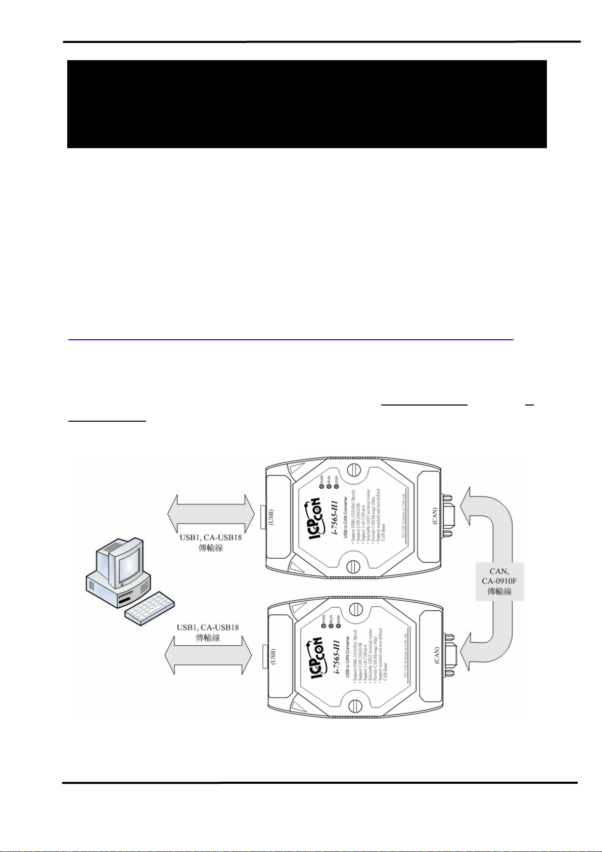
Here, we use two I-7565-H1 modules (called the
7565-H1 (B)) as the example and demonstrate how to use the I-7565-H1
module. The architecture of this example is depicted as below.
I-7565-H1 (A) and the I-
Figure 1-1: Architecture of Example
I-7565-H1/H2 High Speed USB/CAN Converter Quick Start User Guide (Ver 1.0, Sep/2009) 1
Page 2
2. Hardware Installation
Users may need to make a hardware setting before the application.
The detailed illustration is as below :
[ Step1: USB connection & Install I-7565-H1 Driver. ]
Connect the USB ports of the I-7565-H1 A and B to PC respectively.
Then users can refer to the “Driver Installation” chapter in the user’s
manual to complete the I-7565-H1 driver installation.
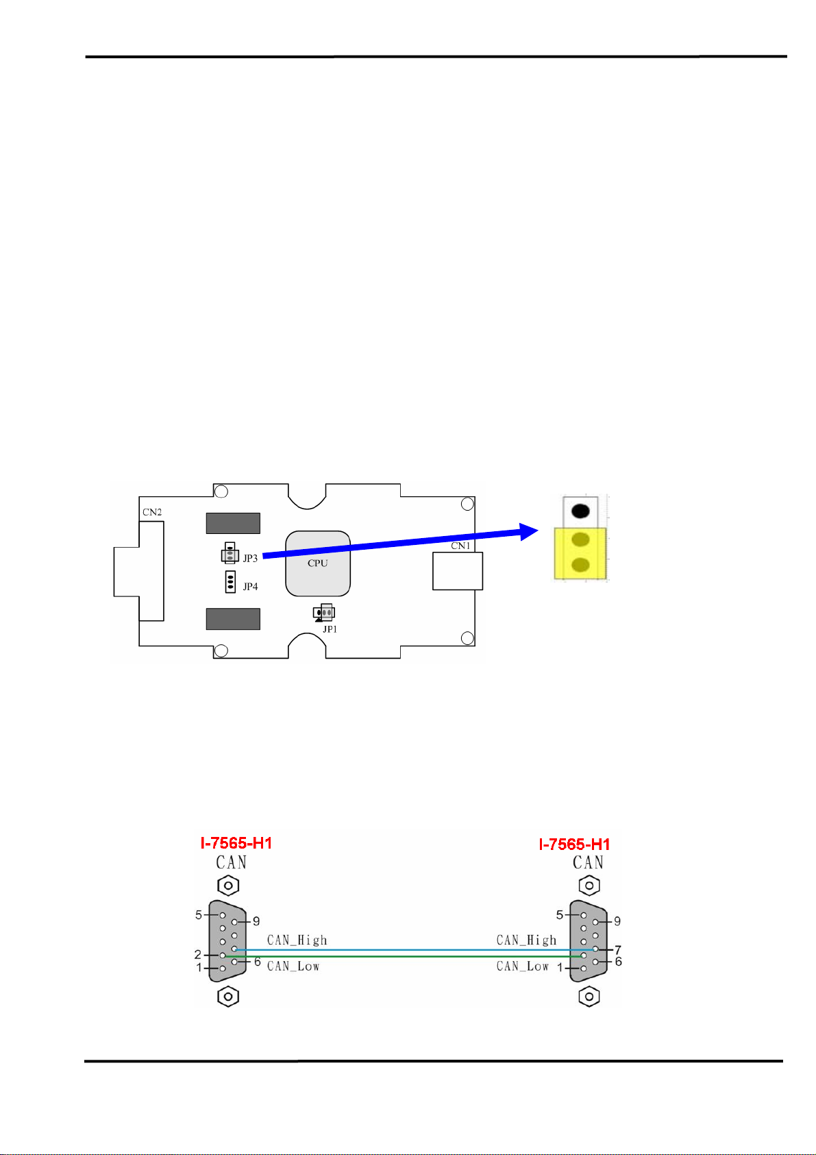
[ Step2: Enable the 120Ω terminator resistor of module A and B. ]
Please open the cover of I-7565-H1 and make sure the JP3 jumper is
in position 1 and 2 like Figure 2-1.
Enable (default),
(Activate)
Figure 2-1: JP3 Jumper Position
[ Step3: CAN bus connection ]
Connect the CAN ports of these two I-7565-H1 modules using the
following structure Figure 2-2.
Figure 2-2: CAN bus Connection
I-7565-H1/H2 High Speed USB/CAN Converter Quick Start User Guide (Ver 1.0, Sep/2009) 2
Page 3
3. Test I-7565-H1 by using I-7565-H1/H2 Utility
Step1: Set the Init / Normal switches on the back of the I-7565-H1 A and
B to the “Normal” position. Then, turn on the DC power. The PWR
LED of the I-7565-H1 A and B will be always turned on. It means
these two I-7565-H1 converters are working in the “
Operation” mode.
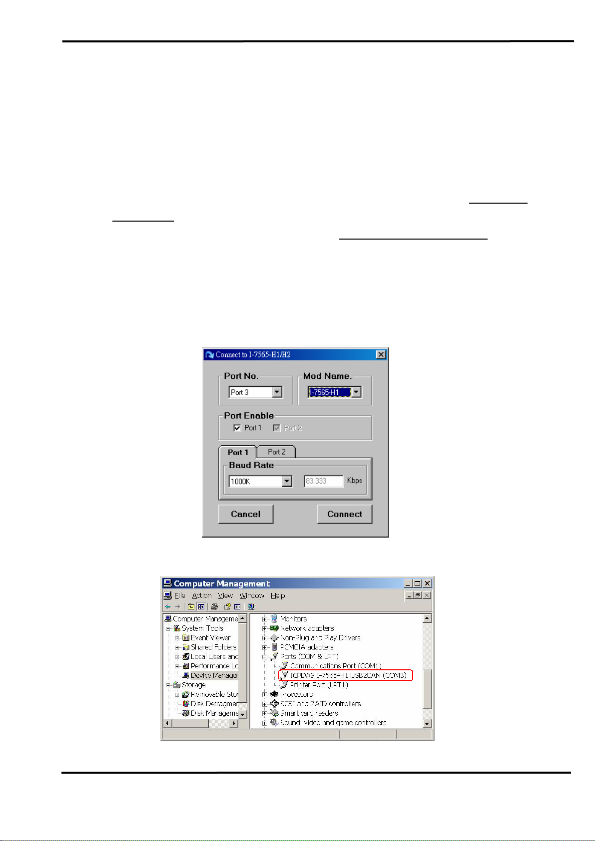
Step2: Run the “I-7565-H1/H2 Utility”,
configure the connection parameters and then click “Connect”
button to connect to the I-7565-H1 A module like Figure 3-1.
Port No : The Virtual COM Port Number (Port3 => Figure 3-2)
Mod Name : The Module Name (I-7565-H1)
Port Enable : Port 1 checked
Baud Rate : 1000K bps
Firmware
I-7565-H1H2_Utility.exe, and
.
Figure 3-1: Connection Screen of I-7565-H1/H2 Utility
Figure 3-2: The Virtual COM Port Number
I-7565-H1/H2 High Speed USB/CAN Converter Quick Start User Guide (Ver 1.0, Sep/2009) 3
Page 4

Step3: Run the I-7565-H1/H2 Utility again and connect to the I-7565-H1 B
module.
Step4: After the connection to I-7565-H1 is successful, the communication
screen will show and the connection parameters are listed in status
bar of I-7565-H1/H2 Utility like Figure 3-3.
Figure 3-3: Communication Screen of I-7565-H1/H2 Utility
Step5: [1] Input the value to the “SendMsg Configuration” frame.
[2] Click the “Add” button to add the CAN message to “CAN
Message Send Area” on Utility A and B.
[3] Click “Send” button and the utility will transfer the CAN
message through the PC USB port automatically.
After the I-7565-H1 A receives the CAN message from PC USB
port and it will send the CAN message from its CAN port. So, the
I-7565-H1 B will receive the CAN message transmitted from
I-7565-H1/H2 High Speed USB/CAN Converter Quick Start User Guide (Ver 1.0, Sep/2009) 4
Page 5

I-7565-H1 A. Then, I-7565-H1 B will send this CAN message from
its USB port to another PC USB port like Figure 3-4 & Figure 3-5.
Figure 3-4: Utility of I-7565-H1 A
Figure 3-5: Utility of I-7565-H1 B
I-7565-H1/H2 High Speed USB/CAN Converter Quick Start User Guide (Ver 1.0, Sep/2009) 5
Page 6

4. LED Indication
There are three LEDs provided to indicate to users what situation the
I-7565-H1/H2 is in. The following is the illustration of these three LEDs
and the position of these three LEDs shows as Figure 4-1.
(1) PWR LED :
It is used to help users to check whether the I-7565-H1/H2 is standby.
If the module is working in “firmware operation” mode, the PWR LED is
always turned on. However, when the module is working in the “firmware
updating” mode, the PWR LED will flash approximately once per second.
(2) RUN LED :
It is used to show whether the I-7565-H1/H2 is transmitting/receiving
CAN messages. The RUN LED will flash whenever a CAN message is
sending or receiving. In I-7565-H2, the RUN LED is shared by CAN1 port
and CAN2 port.
(3) ERR LED :
It is used for demonstrating an error that has occurred. The ERR LED
is normally turned off when the module works in a good condition. When
the Bus-Off error happened, the ERR LED will always turn on until the
Bus-Off condition disappeared. If the CAN/USB buffer built in I-7565H1/H2 overflows or CAN message can’t be sent out successfully, then the
ERR LED will flash continuously. In I-7565-H2, the ERR LED is shared by
CAN1 port and CAN2 port.
Figure 4-1: LED position of I-7565-H1/H2
I-7565-H1/H2 High Speed USB/CAN Converter Quick Start User Guide (Ver 1.0, Sep/2009) 6
Page 7

Table 4-1: LED indication of I-7565-H1/H2
LED Name I-7565-H1/H2 Status LED Status
ALL LED
PWR LED
RUN LED
ERR LED
Hardware Init Fail
All LED always turned on
permanently after reset
Hardware WDT Fail All LED flash per 2 second
Contact to ICP DAS All LED flash take turns
Firmware Updating Mode Flash per second
Firmware Operation Mode Always turned on
Power Off Off
Transmission Flash
Bus Idle Off
Transmission Fail Flash per 100 ms
Buffer Overflow Flash per second
Bus-Off Always turned on
No Error Off
5. Flow Chart for Users’ Program by using API
The following is the basic control flow chart for users’ program
development by using API Library – VCI_CAN.dll.
Figure 5-1: Flow Chart of API Library
I-7565-H1/H2 High Speed USB/CAN Converter Quick Start User Guide (Ver 1.0, Sep/2009) 7
Page 8

Troubleshooting
The following is the common problems of using I-7565-H1/H2
modules.
5.1 How to use I-7565-H1/H2 ?
Please follow the below steps to complete the operation of I-7565-
H1/H2.
(1) Plug I-7565-H1/H2 module to PC via USB port.
(2) Install I-7565-H1/H2 driver.
(3) Execute I-7565-H1/H2 Utility and choose the “virtual com port”,
“module name”, “CAN baud rate” and then connect to I-7565H1/H2 module.
(4) Send / Receive CAN message or configure module parameters by
using I-7565-H1/H2 Utility.
5.2 The Max Data Transfer Rate in I-7565-H1/H2 ?
The max CAN bus data transfer rate in I-7565-H1/H2 is up to 3000
fps and it can be adjusted by I-7565-H1/H2 Utility. If users’ PC
performance is not good enough, the data loss condition may happen. In
this time, users can use “Advanced Config” function to adjust hardware
transfer rate of “CAN to USB” in I-7565-H1/H2 and it may improve the
data loss problem. Remember that hardware data transfer rate can not be
lower than the current CAN bus flow, or the data loss will happen in I7565-H1/H2 module.
5.3 How many I-7565-H1/H2 could be applied to one PC ?
In theory, there is no the limitation. It supports synchronous operation
in a PC with more than one I-7565-H1/H2 modules but the total
communication efficiency depends on the PC hardware performance.
I-7565-H1/H2 High Speed USB/CAN Converter Quick Start User Guide (Ver 1.0, Sep/2009) 8
 Loading...