

Page 1

I-7000 DIO Manual
Warranty
All products manufactured by ICP DAS are warranted
against defective materials for a period of one year from the date
of delivery to the original purchaser.
Warning
ICP DAS assume no liability for damages consequent to
the use of this product. ICP DAS reserves the right to change this
manual at any time without notice. The information furnished by
ICP DAS is believed to be accurate and reliable. However, no
responsibility is assumed by ICP DAS for its use, nor for any infringements of patents or other rights of third parties resulting from
its use.
Copyright
Copyright 1999 by ICP DAS. All rights are reserved.
Trademark
The names used for identification only maybe registered
trademarks of their respective companies.
I-7000 DIO ManualRev:B1.2
Date:2000-02
1
Page 2

Table of Contents
1. Introduction.....................................................4
1.1 More Information.......................................4
1.2 Pin Assignment ..........................................5
1.3 Specifications.............................................9
1.4 Block Diagram.........................................13
1.5 Wire Connection ......................................21
1.6 Quick Start ...............................................24
1.7 Default Setting .........................................24
1.8 Jumper Setting .........................................24
1.9 Configuration Tables ...............................24
2. Command ......................................................26
2.1 %AANNTTCCFF....................................28
2.2 #** ...........................................................29
2.3 #AABBDD...............................................30
2.4 #AAN.......................................................33
2.5 $AA2........................................................34
2.6 $AA4........................................................35
2.7 $AA5........................................................36
2.8 $AA6........................................................37
2.9 $AAF .......................................................38
2.10 $AAM ....................................................39
2.11 $AAC .....................................................40
2.12 $AACN ..................................................41
2
I-7000 DIO Manual Rev:B1.2
Page 3

2.13 $AALS ...................................................42
2.14 @AA ......................................................43
2.15 @AA(Data)............................................44
2.16 ~AAO(Data) ..........................................46
2.17 ~** .........................................................47
2.18 ~AA0 .....................................................48
2.19 ~AA1 .....................................................49
2.20 ~AA2 .....................................................50
2.21 ~AA3EVV .............................................51
2.22 ~AA4V...................................................53
2.23 ~AA5V...................................................55
3. Application Note ...........................................57
3.1 INIT* pin Operation ................................57
3.2 Module Status ..........................................57
3.3 Dual Watchdog Operation .......................58
3.4 Reset Status..............................................58
3.5 Digital Output ..........................................58
3.6 Latch Digital Input...................................59
4 DN Module .....................................................60
4.1 DN-SSR4 .................................................60
4.2 DN-PR4 ...................................................61
4.3 RM-104, RM-108, RM-116.....................62
4.4 RM-204, RM-208, RM-216.....................63
4.5 Application...............................................64
I-7000 DIO ManualRev:B1.2
3
Page 4

1. Introduction
I-7000 is a family of network data acquisition and control
modules. They provide analog-to-digital, digital-to-analog, digital input/output, timer/counter and other functions. These modules can be remote controlled by a set of commands. The DIO
modules support TTL signal, photo-isolated digital input, relay
contact output , solid-state relay output, PhotoMOS output and
open-collector output. Reference Sec.1.3 for detail information.
1.1 More Information
Refer to I-7000 Bus Converter User Manual chapter
1 for more information as following:
1.1 I-7000 Overview
1.2 I-7000 Related Documentation
1.3 I-7000 Command Features
1.4 I-7000 System Network Configuration
1.5 I-7000 Dimension
4
I-7000 DIO Manual Rev:B1.2
Page 5
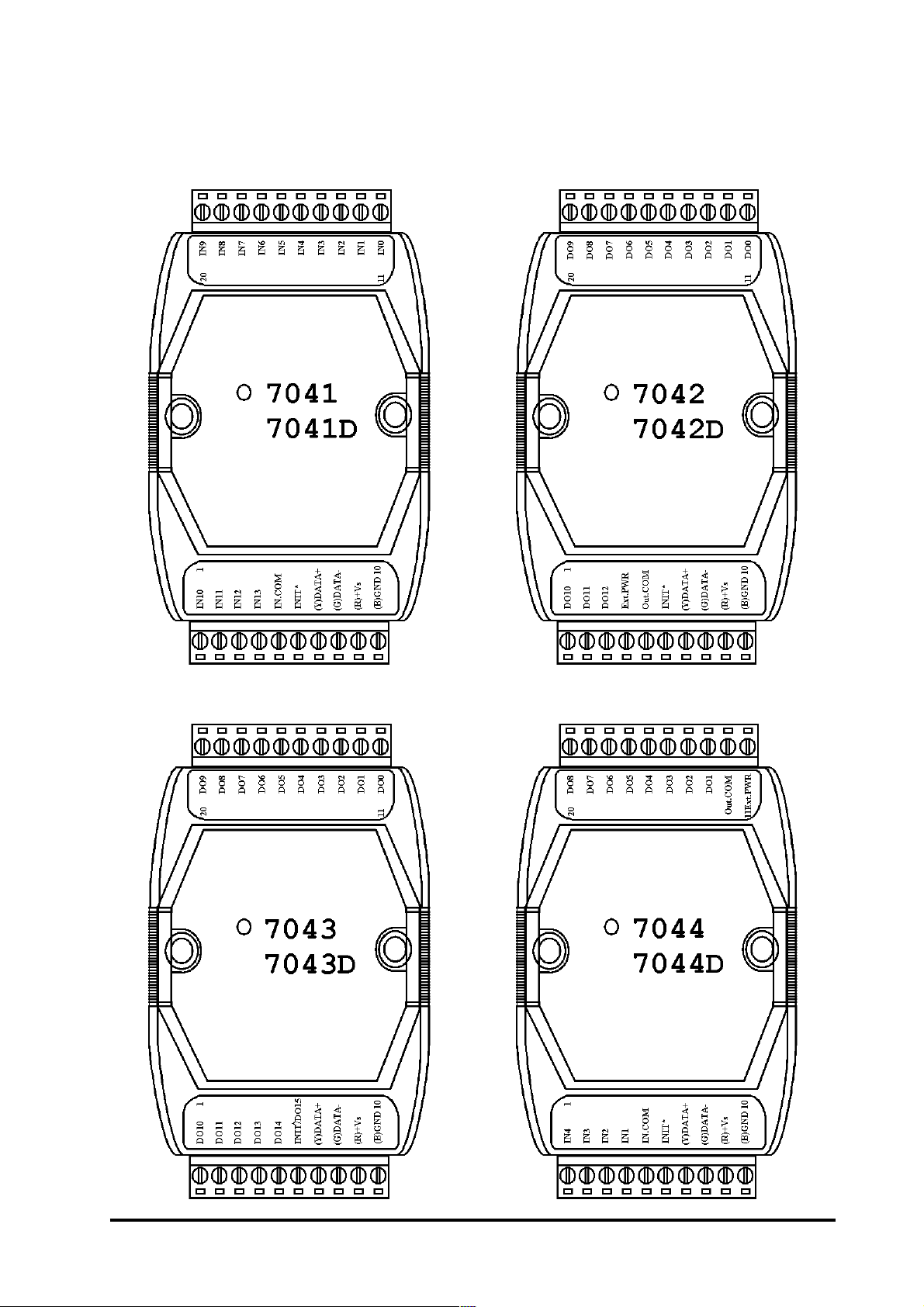
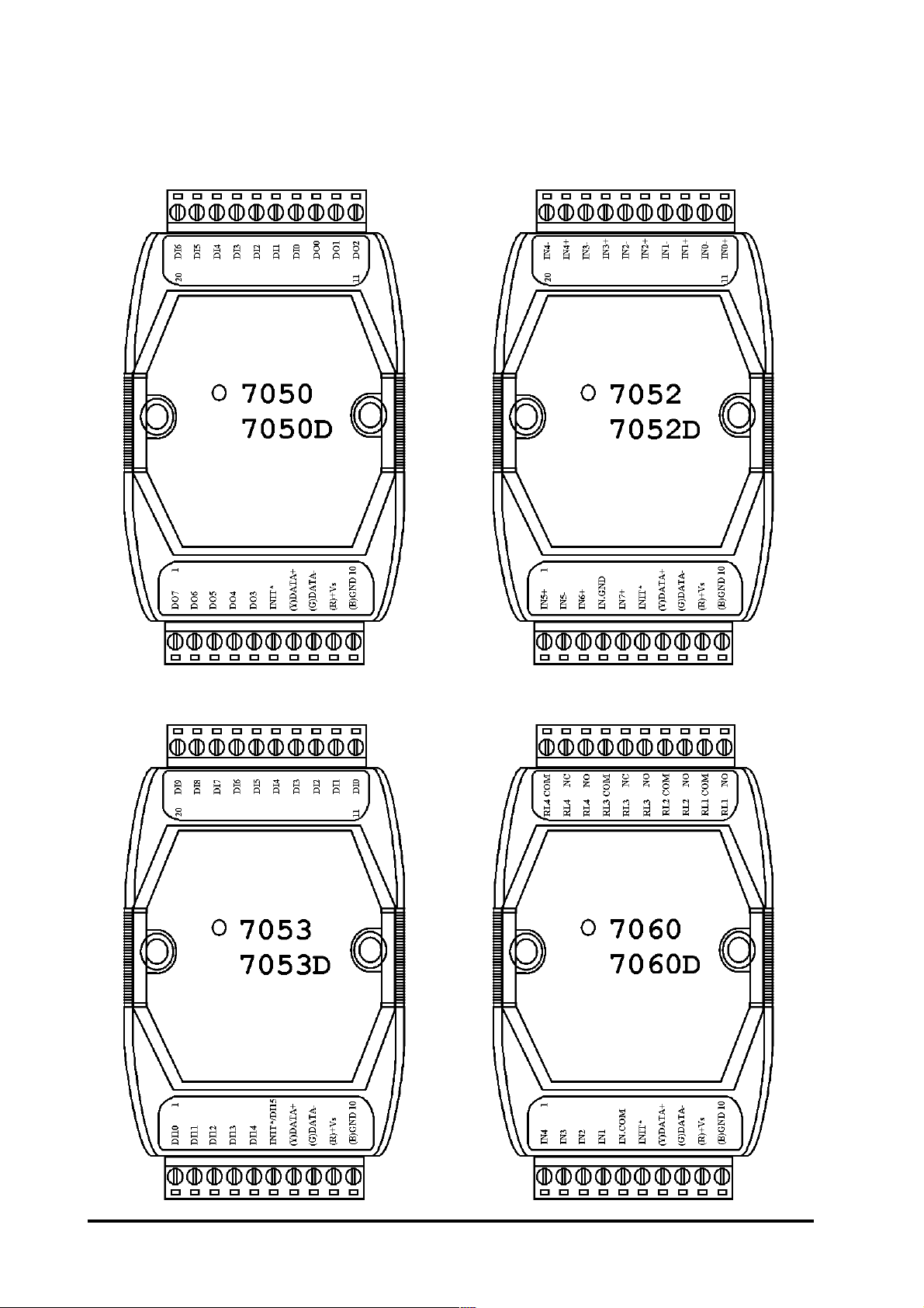
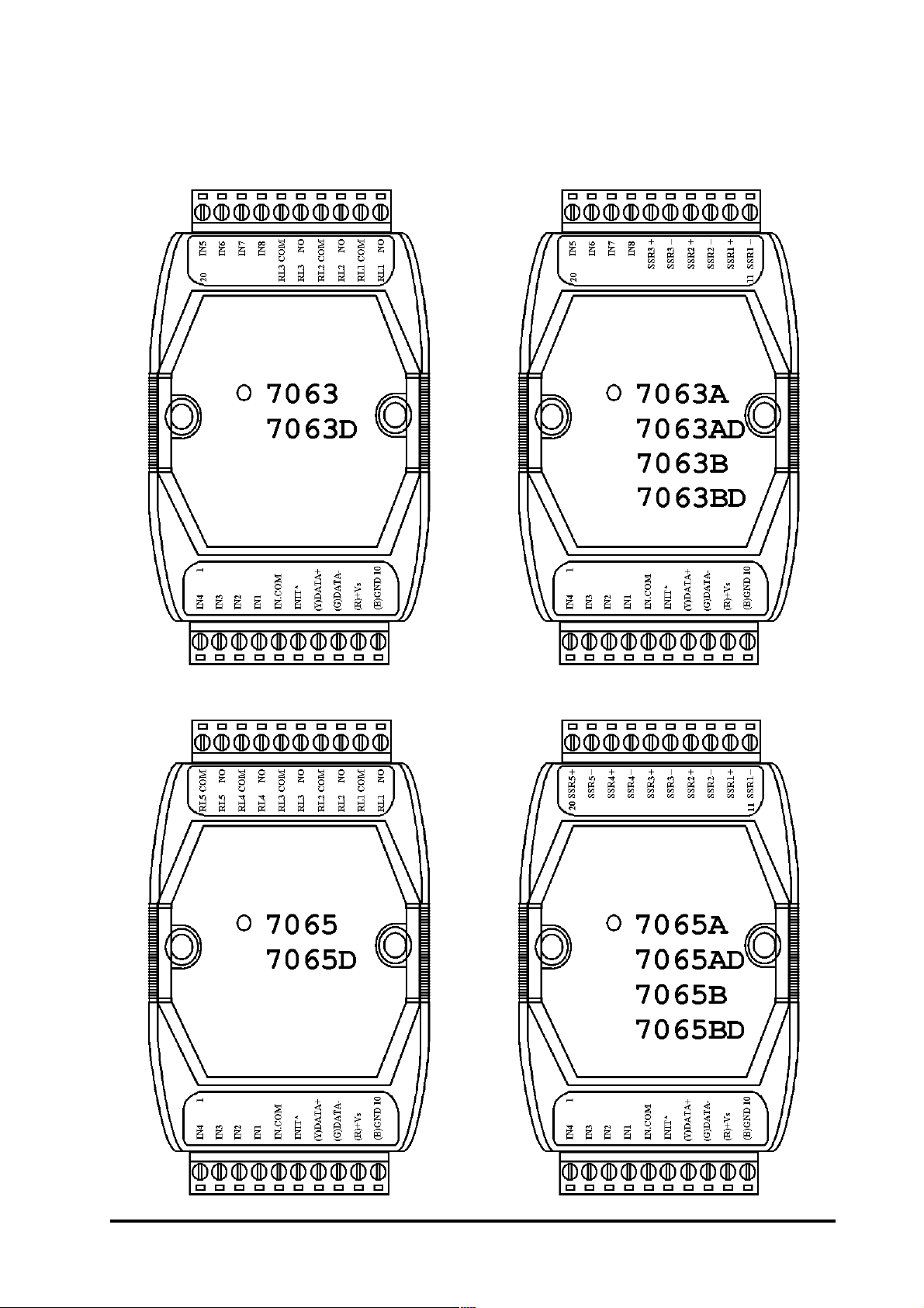
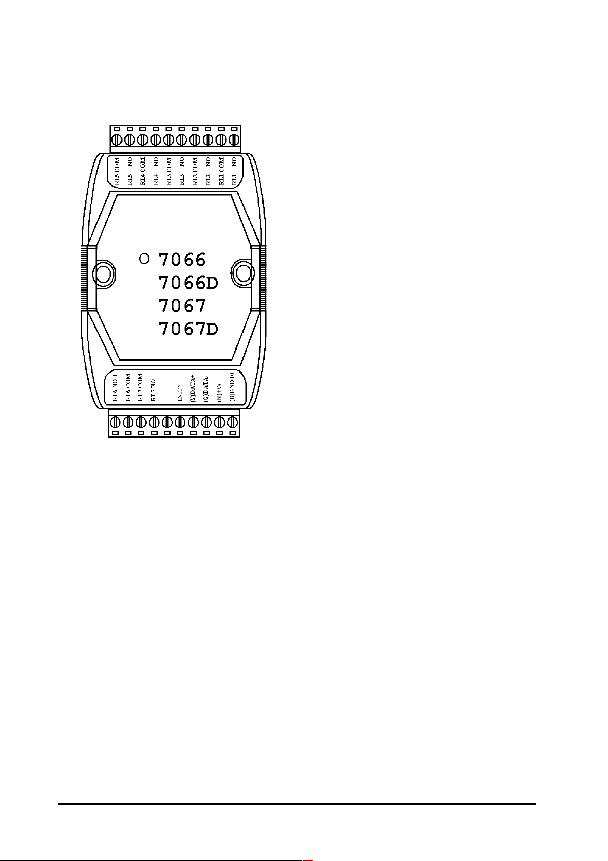
1.2 Pin Assignment
I-7000 DIO ManualRev:B1.2
5
Page 6
6
I-7000 DIO Manual Rev:B1.2
Page 7
I-7000 DIO ManualRev:B1.2
7
Page 8
8
I-7000 DIO Manual Rev:B1.2
Page 9
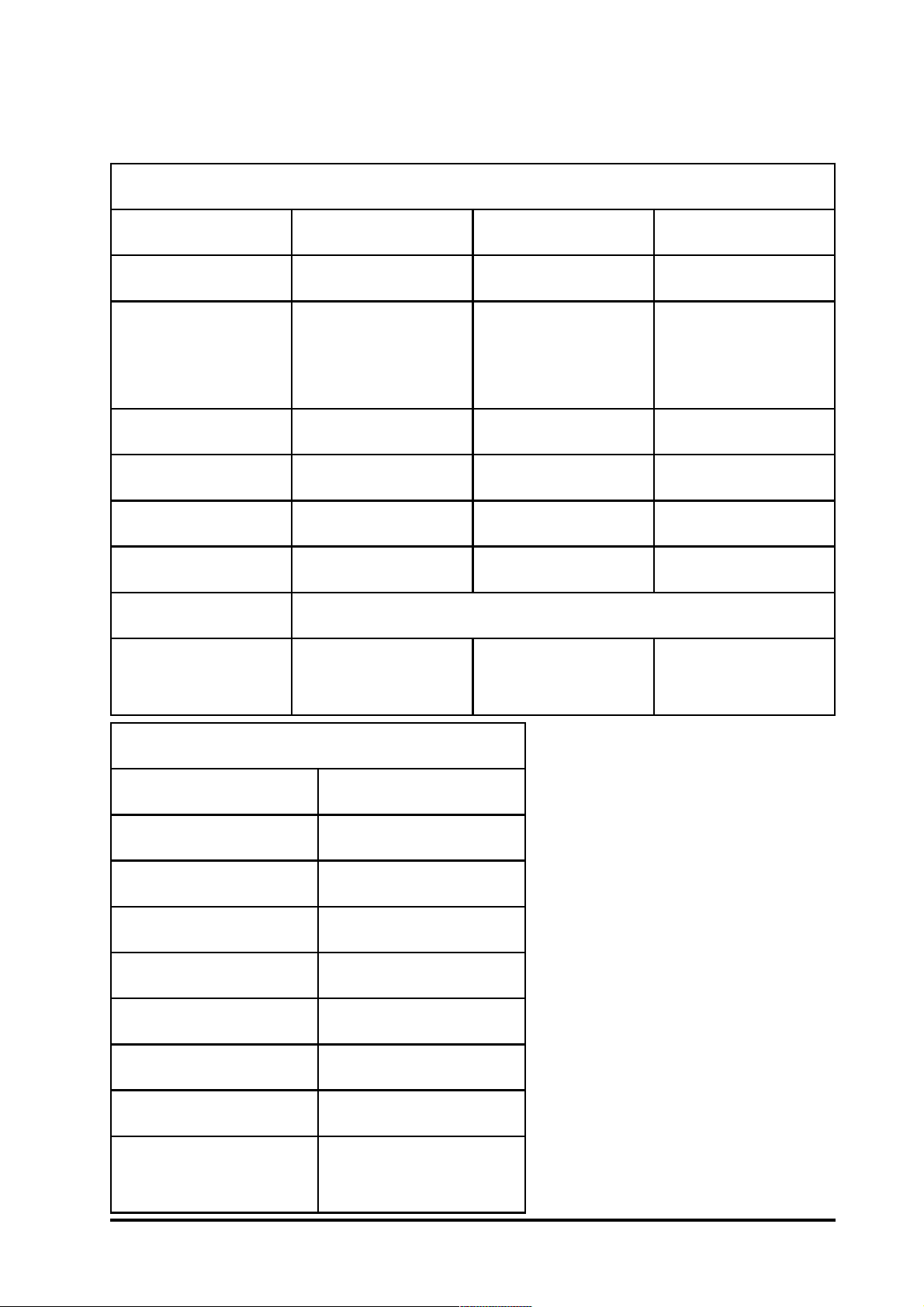
1.3 Specifications
D14/1407-ID25/2507-ID35/3507-I
slennahCtupnI41861
seludoMtupnIlatigiD
htiwnoitalosI
noitalosI
egatloVnoitalosIsmrV0573smrV0005detalosI-noN
0leveLlatigiDxamV1+xamV1+xamV2+
1leveLlatigiDV03+ot4+V03+ot4+V03+ot4+
ecnadepmItupnIsmhoK3smhoK3smho028
tupnIrewoPCDV03+ot01+
rewoP
noitpmusnoC
nommoC
ecruoS
)1407-I(W2.0
)D1407-I(W9.0
eludoMtuptuOSOMotohP
nommoc2
dnuorg
)2507-I(W2.0
dnalaitnereffid6
detalosI-noN
)3507-I(W7.0
)D2507-I(W6.0
)D3507-I(W9.0
slennahCtuptuO7
tnerruCdaoLA31.0
egatloVdaoLxamV053
egatloVnoitalosICAV0005
emiTnOnruTpytSm7.0
emiTffOnruTpytSm50.0
tupnIrewoPCDV03+ot01+
rewoP
noitpmusnoC
D66/6607-I
)6607-I(W5.0
)D6607-I(W8.0
I-7000 DIO ManualRev:B1.2
9
Page 10
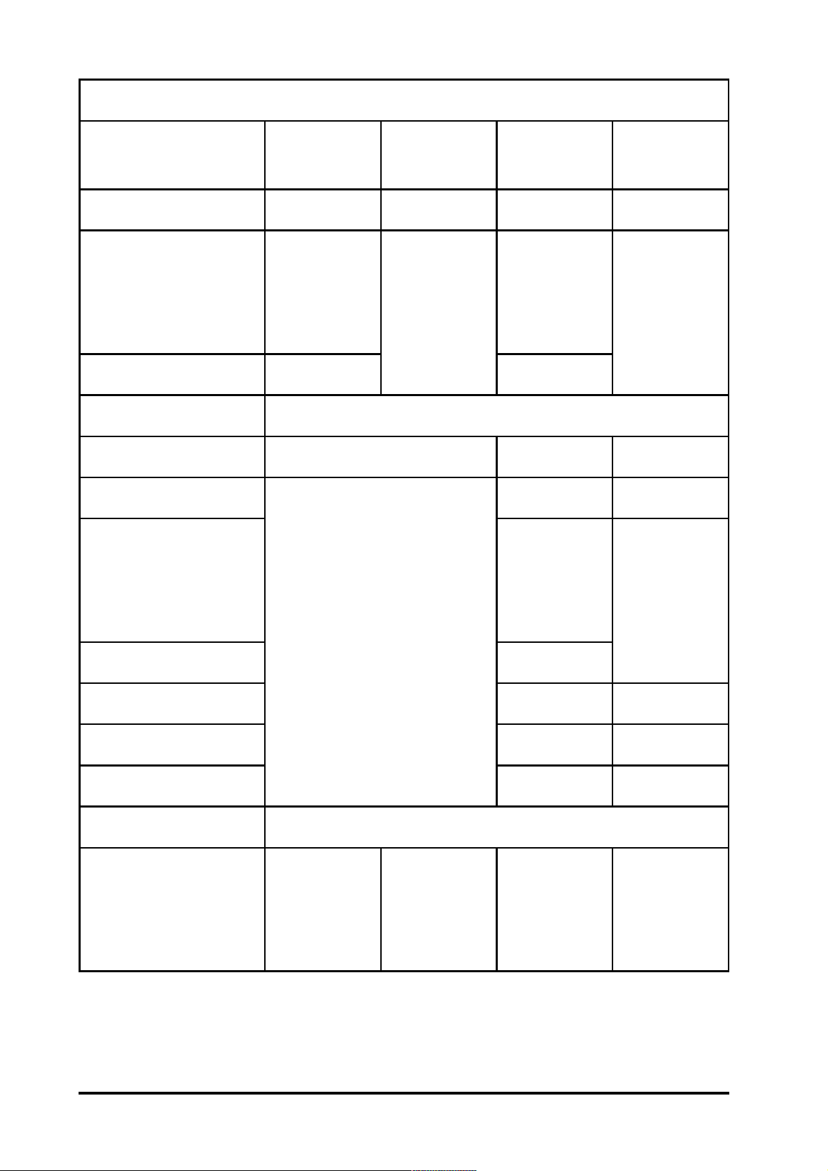
seludoMtuptuOrotcelloCnepO
2407-I
D2407-I
slennahCtuptuO316188
noitalosI
htiw
noitalosI
nommoC
rewoP
egatloVnoitalosIsmrV0573smrV0573
egatloVdaoLV03+xaM
tnerruCdaoLxaMAm001Am573Am03
slennahCtupnI
3407-I
D3407-I
-alosI-noN
noit
4407-I
D4407-I
noitalosI
htiw
nommoC
rewoP
47
noitalosI
0507-I
D0507-I
noit
-alosI-noN
noitalosI
stupnI-oN
egatloVnoitalosIsmrV0573
0leveLlatigiDxamV1xamV1
1leveLlatigiDV03ot4V03ot5.3
ecnadepmItupnIsmhoK3
tupnIrewoPCDV03+ot01+
W0.1
rewoP
noitpmusnoC
)2407-I(
W7.1
)D2407-I(
W4.0
)3407-I(
W1.1
)D3407-I(
htiw
W0.1
W7.1
nommoC
ecruoS
)4407-I(
)D4407-I(
-alosI-noN
noit
W4.0
)0507-I(
W1.1
)D0507-I(
10
I-7000 DIO Manual Rev:B1.2
Page 11
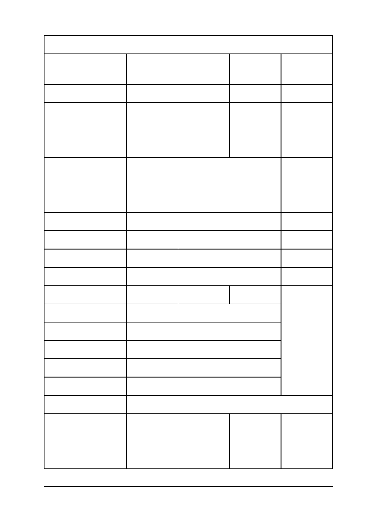
seludoMtuptuOyaleR
0607-I
D0607-I
3607-I
D3607-I
5607-I
D5607-I
7607-I
D7607-I
slennahCtuptuO4357
:2LR,1LR
AmroF
epyTyaleR
AmroFAmroFAmroF
:4LR,3LR
CmroF
A6.0
CAV521@
CAV052@A5
A5.0
CAV021@
gnitaRtcatnoC
A2
CDV03@
CDV03@A5
A0.1
CDV42@
htgnertSegruSV005V0004V0051
emiTetarepOSm3.xaMSm6.xaMSm5
emiTesaeleRSm2.xaMSm3.xaMSm2
efiL.niM01*5
5
.spo01
5
.spo01
5
slennahCtupnI484
noitalosIecruoSnommoChtiwnoitalosI
egatloVnoitalosIsmrV0573
0leveLlatigiDxamV1+
1leveLlatigiDV03+ot4+
ecnadepmItupnIsmhoK3
tupnIrewoPCDV03+ot01+
W3.1
rewoP
)0607-I(
W0.1
)3607-I(
W3.1
W5.1
)5607-I(
.spo
tupnioN
)7607-I(
noitpmusnoC
W9.1
)D0607-I(
I-7000 DIO ManualRev:B1.2
W5.1
)D3607-I(
W2.2
)D5607-I(
W2.2
)D7607-I(
11
Page 12
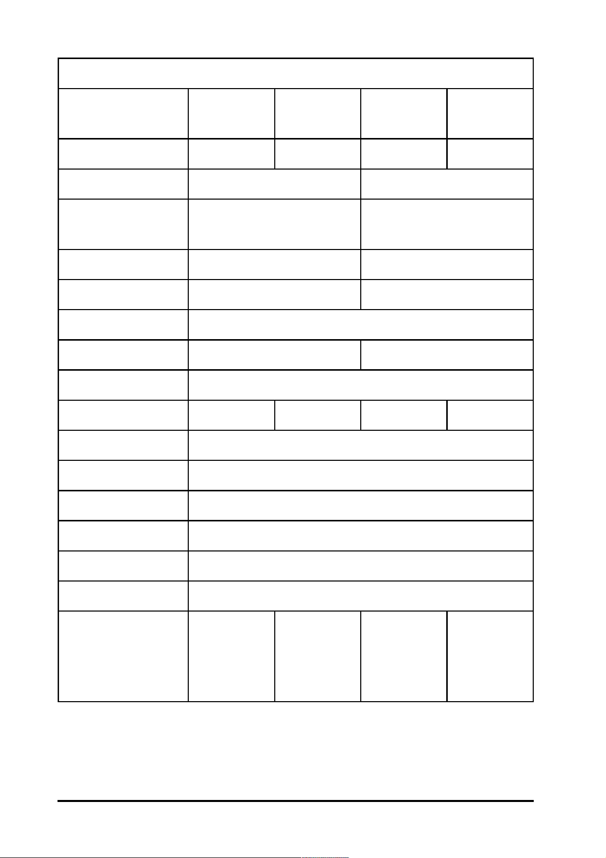
seludoMtuptuOyaleRetatS-diloS
A3607-I
DA3607-I
slennahCtuptuO 3535
epyTRSSnepOlamroN,RSS-CAnepOlamroN,RSS-CD
egatloVdaoL
egnaR
tnerruCegakaeLsmrAm5.1Am1.0
tnerruCdaoLxaMsmrA0.1A0.1
emiTetarepO.niMSm1
emiTesaeleR.niMSm1+elcyc2/1Sm1
htgnertScirtceleiDsmrV0052
A5607-I
DA5607-I
smrV562ot42CDV03ot3
B3607-I
DB3607-I
B5607-I
DB5607-I
slennahCtupnI8484
noitalosIecruoSnommoChtiwnoitalosI
egatloVnoitalosIsmrV0573
0leveLlatigiDxamV1+
1leveLlatigiDV03+ot4+
ecnadepmItupnIsmhoK3
tupnIrewoPCDV03+ot01+
W7.0
rewoP
noitpmusnoC
)A3607-I(
W5.1
)DA3607-I(
W8.0
)A5607-I(
W6.1
)DA5607-I(
W6.0
)B3607-I(
W4.1
)DB3607-I(
W7.0
)B5607-I(
W5.1
)DB5607-I(
12
I-7000 DIO Manual Rev:B1.2
Page 13
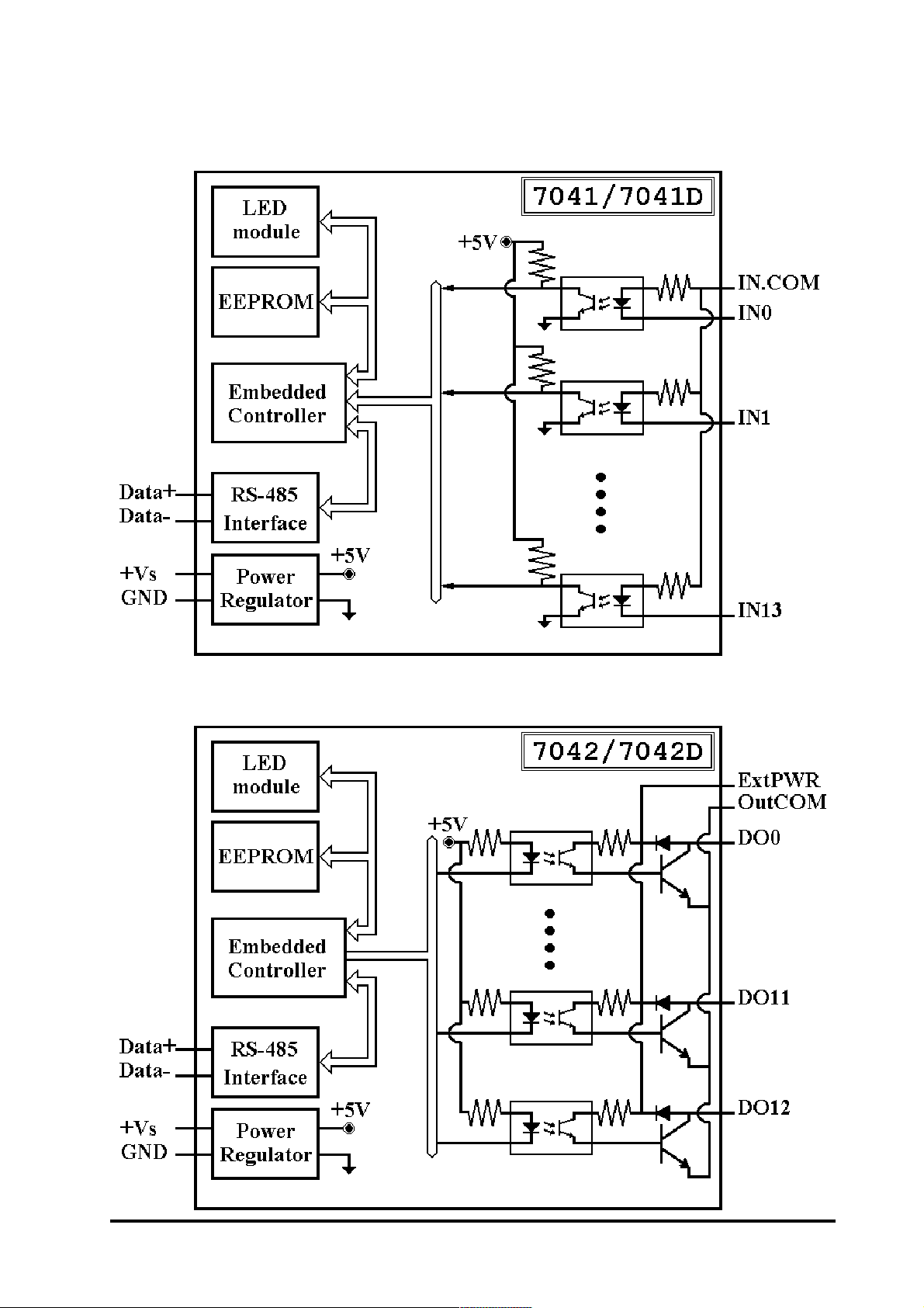
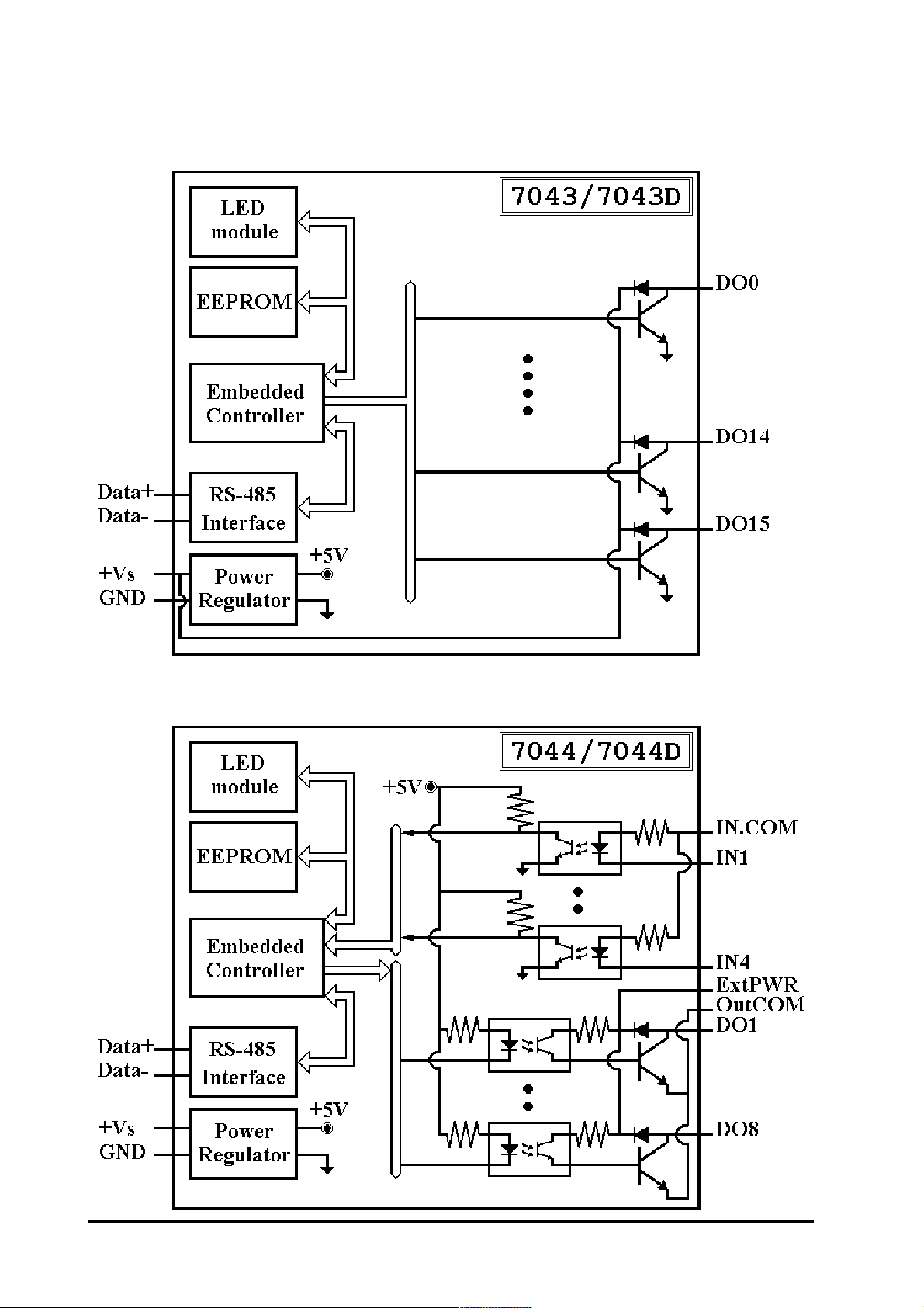
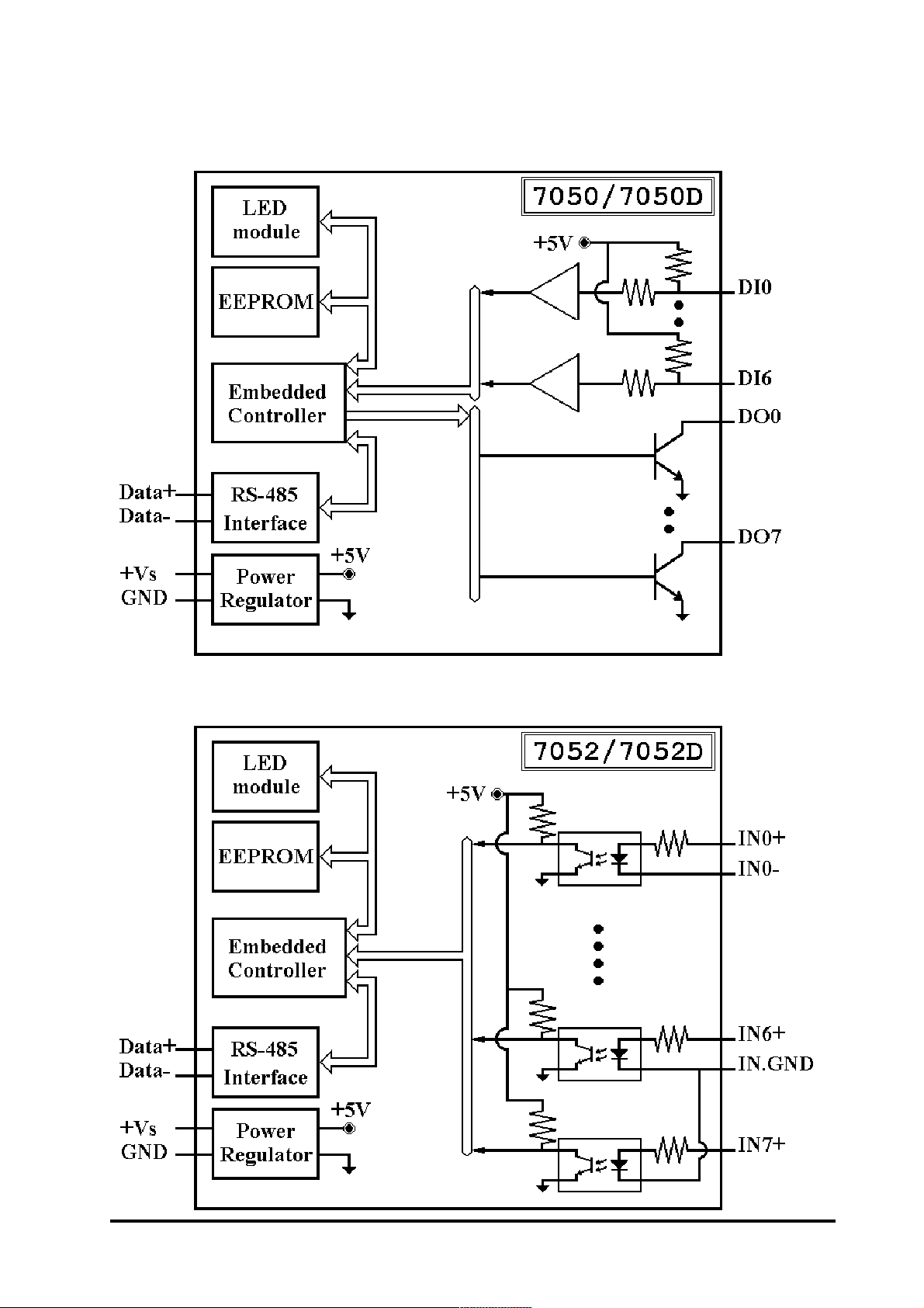
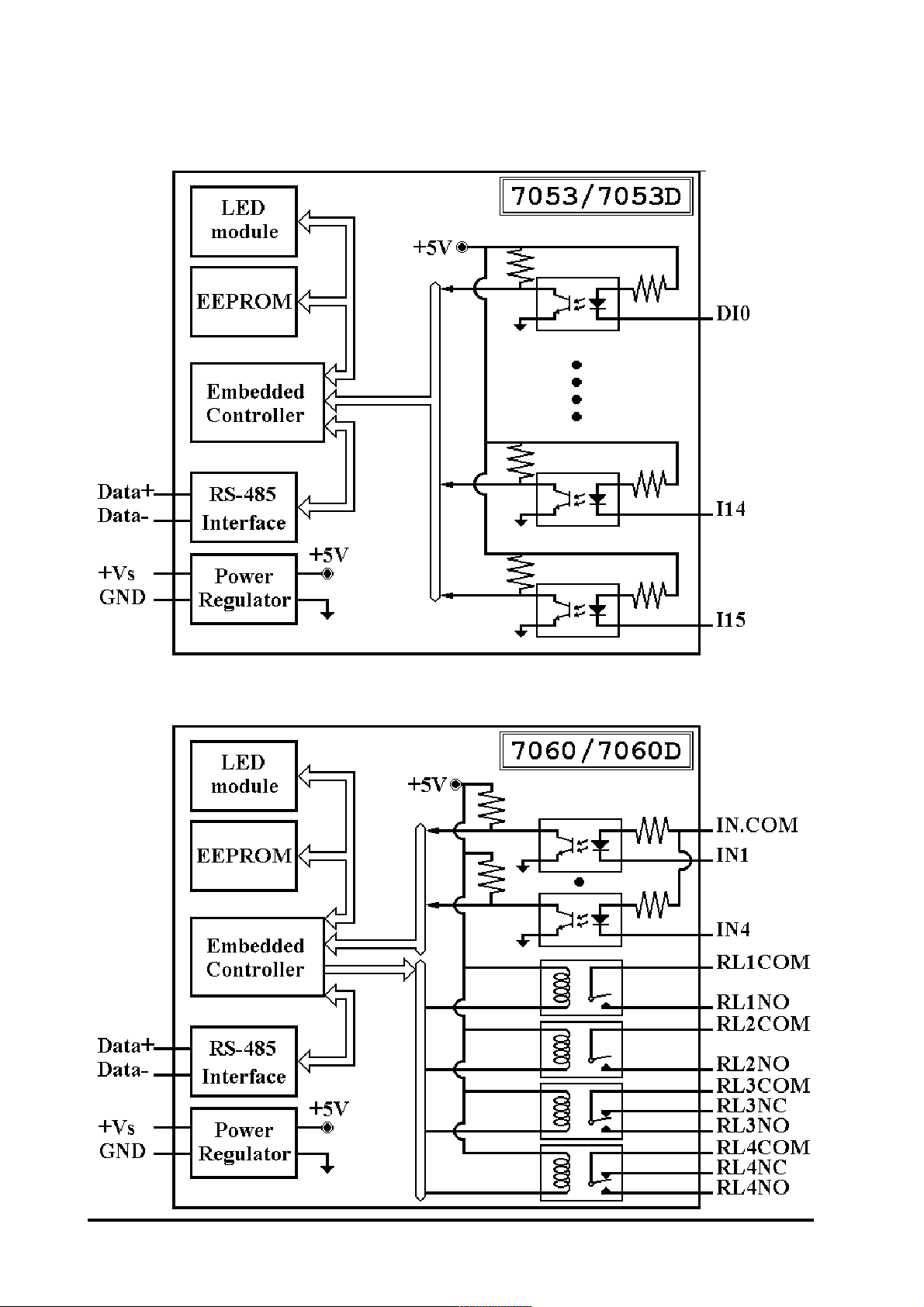
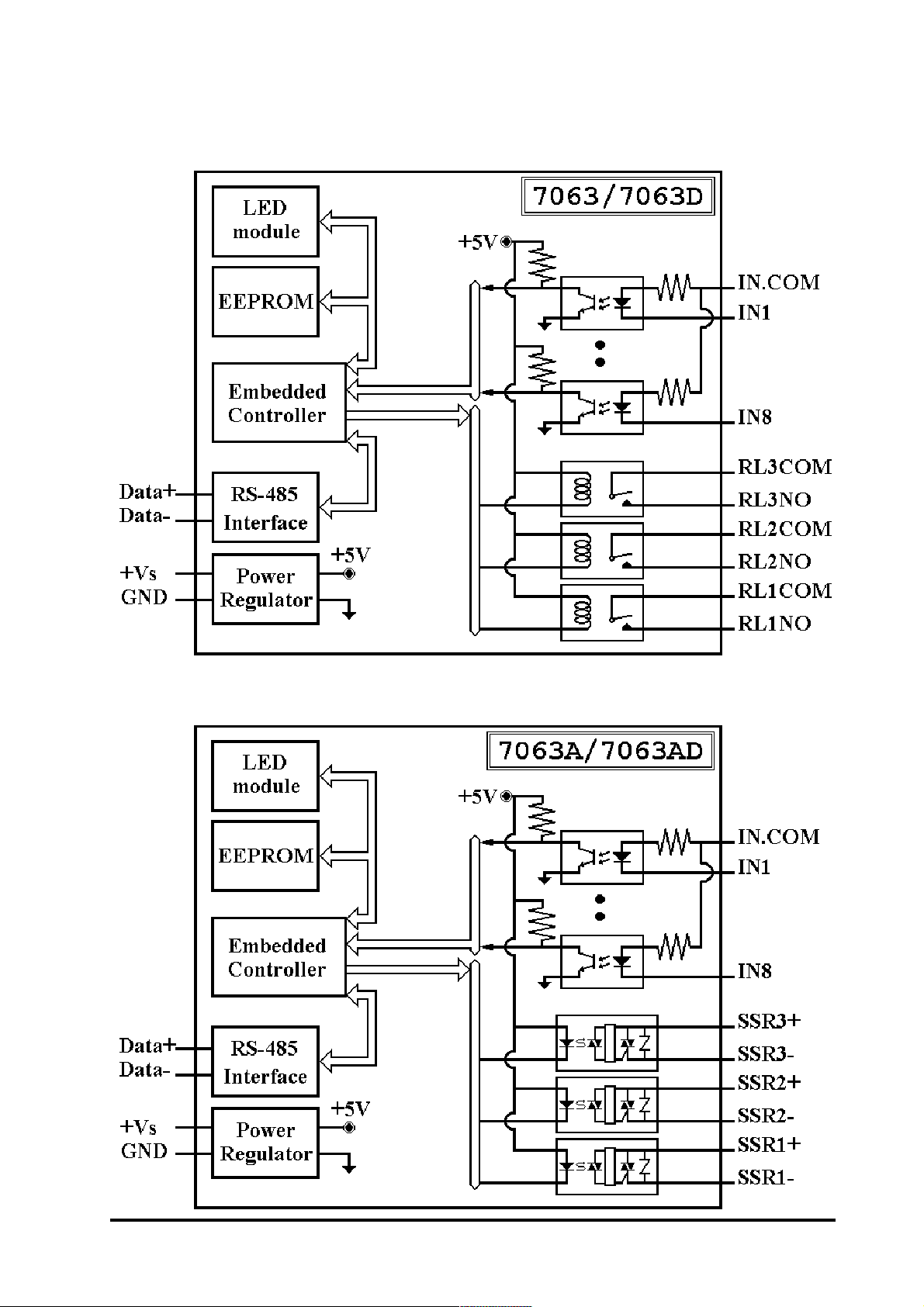
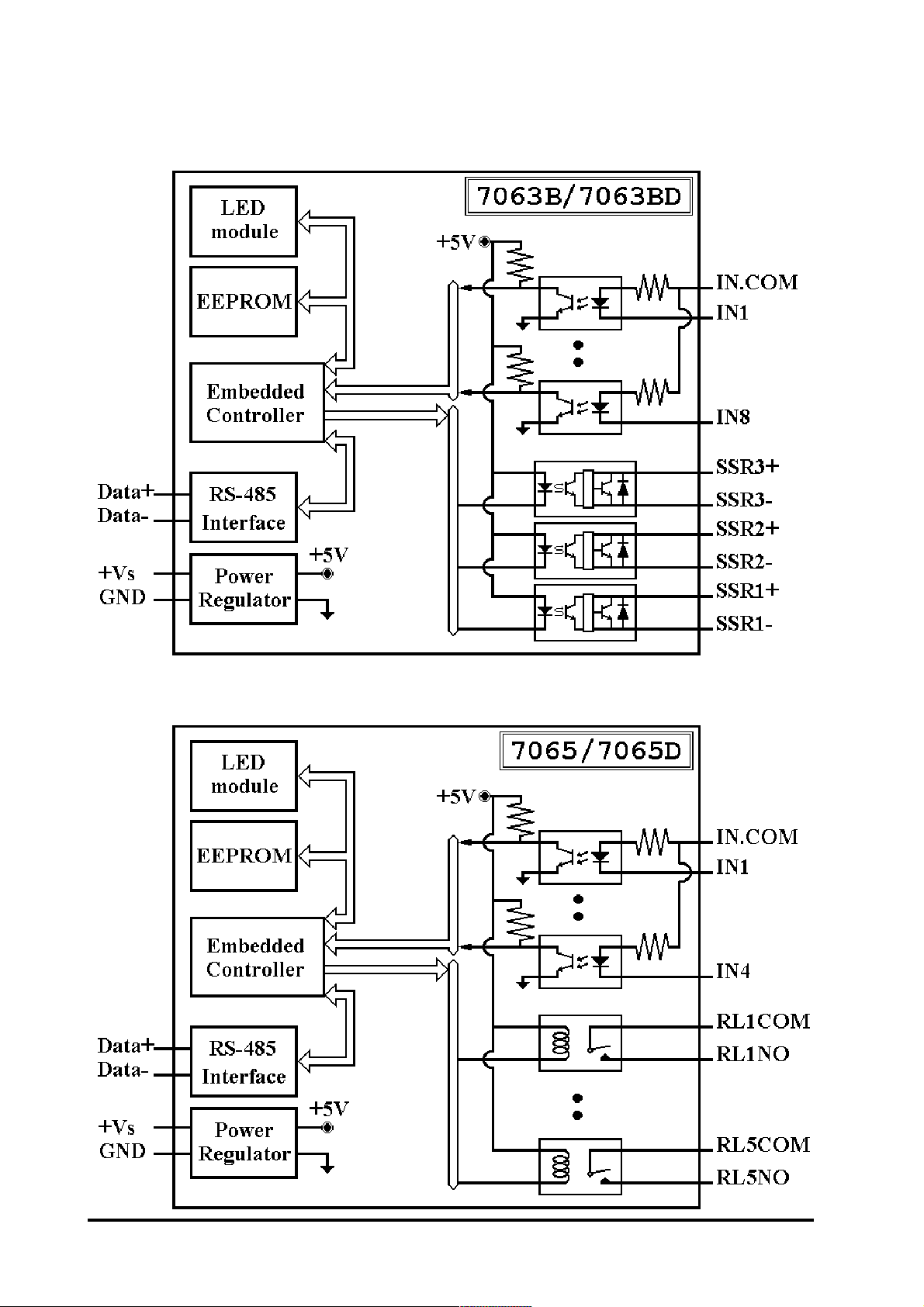
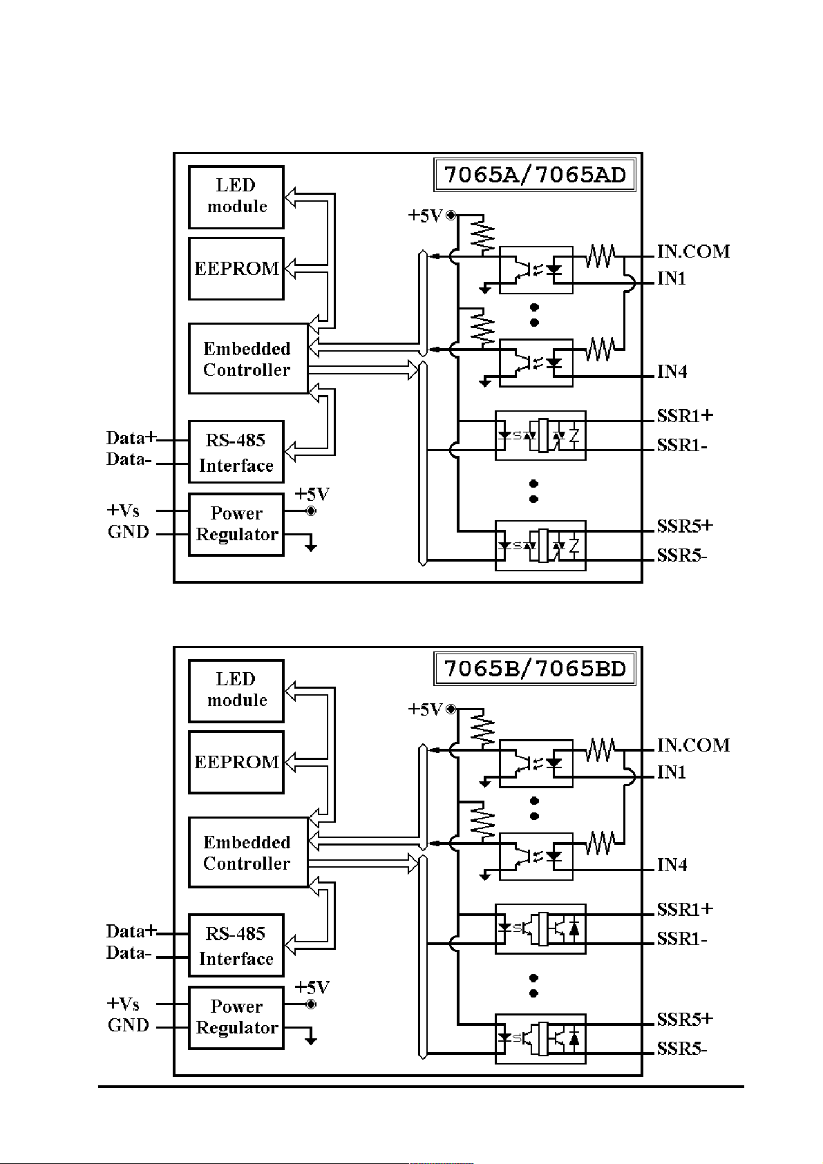
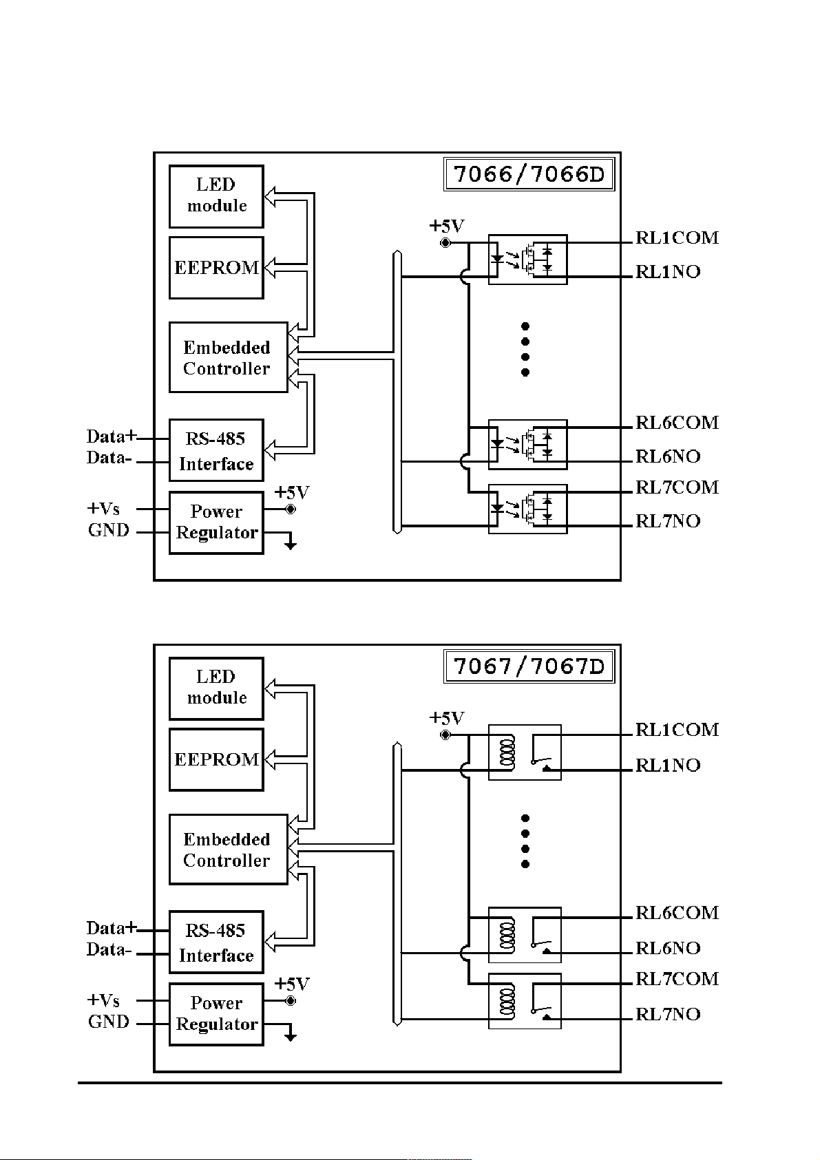
1.4 Block Diagram
I-7000 DIO ManualRev:B1.2
13
Page 14
14
I-7000 DIO Manual Rev:B1.2
Page 15
I-7000 DIO ManualRev:B1.2
15
Page 16
16
I-7000 DIO Manual Rev:B1.2
Page 17
I-7000 DIO ManualRev:B1.2
17
Page 18
18
I-7000 DIO Manual Rev:B1.2
Page 19
I-7000 DIO ManualRev:B1.2
19
Page 20
20
I-7000 DIO Manual Rev:B1.2
Page 21

1.5 Wire Connection
Dry Contact signal input
I-7052/52D
I-7050/50D/53/53D
TTL/CMOS signal input
I-7052/52D
I-7050/50D/53/53D
I-7041/41D/44/44D/60/60D/63/
63D/63A/63AD/63B/63BD/65/
65D/65A/65AD/65B/65BD
I-7000 DIO ManualRev:B1.2
I-7041/41D/44/44D/60/60D/63/
63D/63A/63AD/63B/63BD/65/
65D/65A/65AD/65B/65BD
21
Page 22
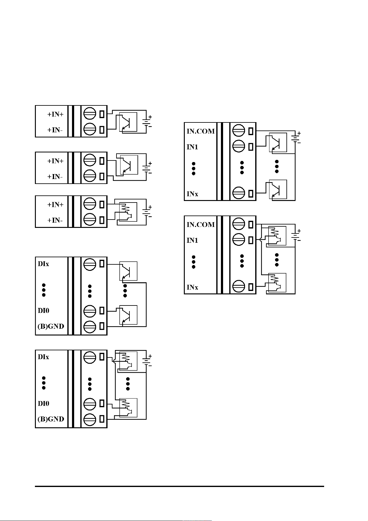
Open Collector signal input
I-7041/41D/44/44D/60/60D/63/
I-7052/52D
I-7050/50D/53/53D
63D/63A/63AD/63B/63BD/65/
65D/65A/65AD/65B/65BD
22
I-7000 DIO Manual Rev:B1.2
Page 23
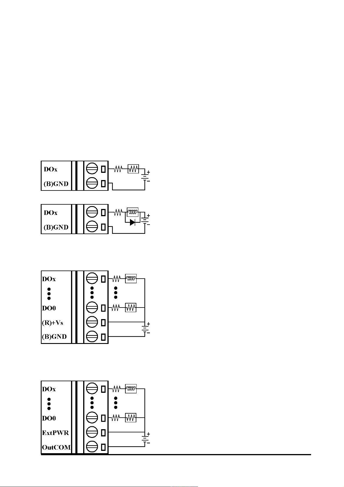
Open Collector output
I-7050/50D
Note : while connect inductive
load(for example to drive relay),
the diode is needed for prevent
the counter EMF.
I-7043/43D
I-7042/42D/44/44D
I-7000 DIO ManualRev:B1.2
23
Page 24
1.6 Quick Start
Refer to I-7000 Bus Converter User Manual and Get-
ting Start for detail.
1.7 Default Setting
Default setting for I-7000 DIO modules :
! Address : 01
! Baudrate : 9600 bps
! Type : Type 40 for DIO mode
! Checksum Disable
! I-7043/43D jumper setting at DO15
! I-7053/53D jumper setting at DI15
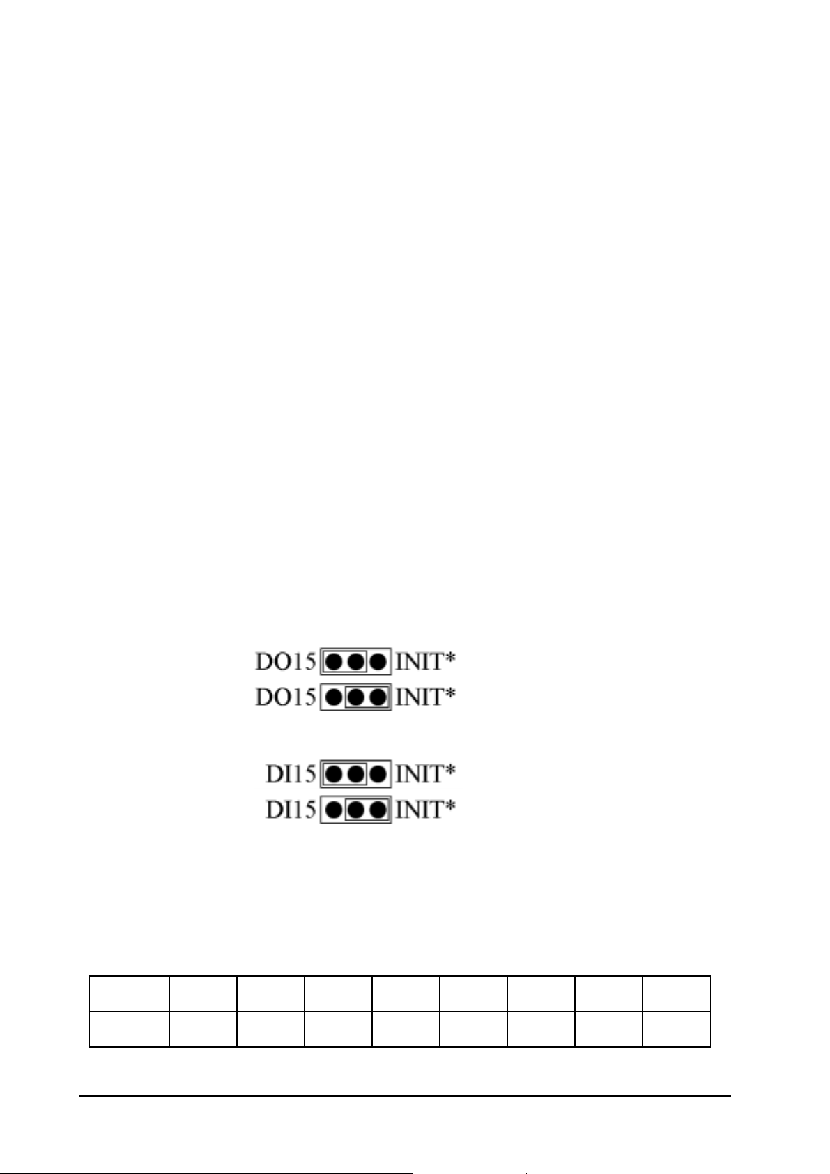
1.8 Jumper Setting
I-7043/43D : Jumper J3 for select the pin INIT*/DO15
Select DO15
Select INIT*
I-7053/53D : Jumper J1 for select the pin INIT*/DI15
Select DI15
Select INIT*
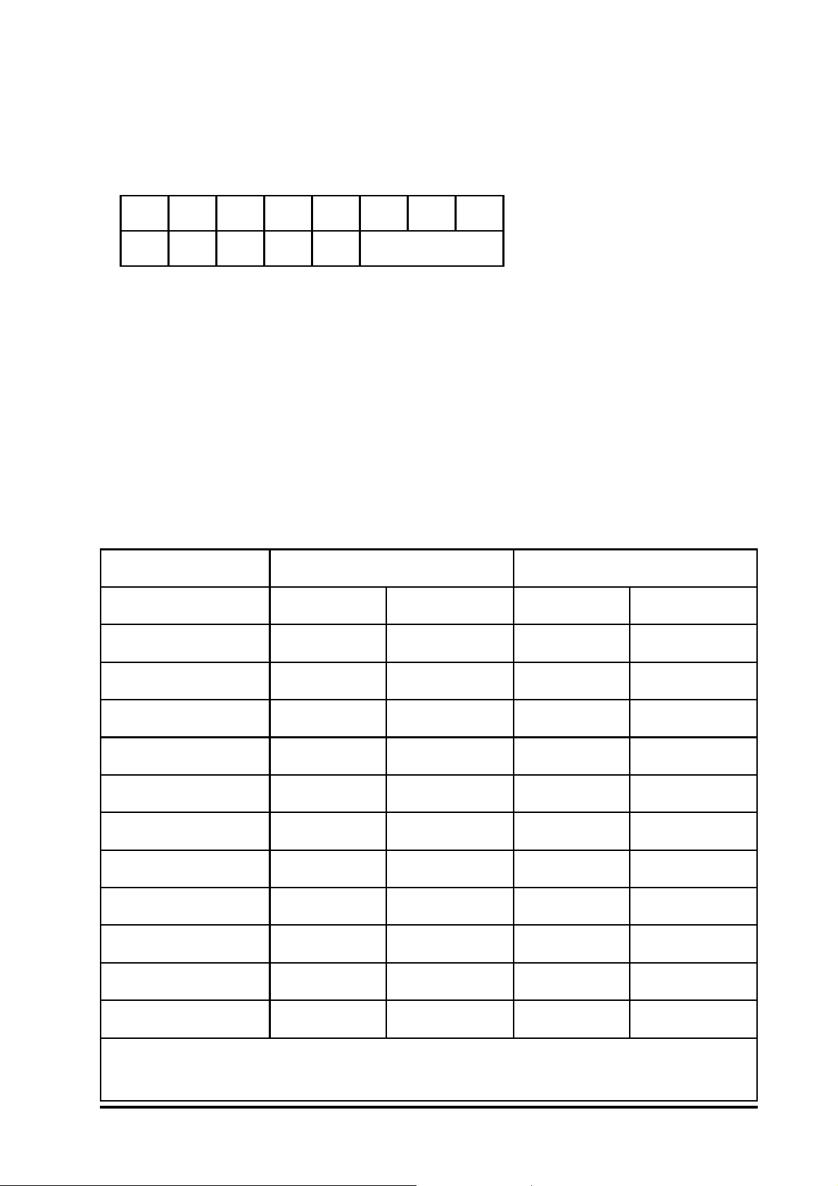
1.9 Configuration Tables
Configuration Table of I-7000 DIO modules
Baudrate Setting (CC)
edoC30405060708090A0
etarduaB0021004200840069002910048300675002511
24
I-7000 DIO Manual Rev:B1.2
Page 25
Type Setting (TT)
Type = 40 for DIO mode
Data Format Setting (FF)
76543210
1*2* 000 3*
*1 :Counter Update Direction : 0=Falling Edge, 1=Rising Edge
*2 :Checksum Bit : 0=Disable, 1=Enable
*3 :7050 = 0 (Bit[2.1.0] = 000), 7060 = 1 (Bit[2.1.0] = 001)
7052 = 2 (Bit[2.1.0] = 010), 7053 = 3 (Bit[2.1.0] = 011)
Read Digital Input/Output Data Format
Data of $AA6,$AA4,$AALS : (First Data)(Second Data)00
Data of @AA : (First Data)(Second Data)
ataDtsriFataDdnoceS
D14/1407-I)31-8(IDF3ot00)7-0(IDFFot00
D24/2407-I)21-8(ODF1ot00)7-0(ODFFot00
D34/3407-I)51-8(ODFFot00)7-0(ODFFot00
D44/4407-I)8-1(ODFFot00)4-1(IDF0ot00
D05/0507-I)7-0(ODFFot00)6-0(IDF7ot00
D25/2507-I)7-0(IDFFot000000
D35/3507-I)51-8(IDFFot00)7-0(IDFFot00
D06/0607-I)4-1(ODF0ot00)4-1(IDF0ot00
1*
s3607-I
)3-1(OD70ot00)8-1(IDFFot00
2*
s5607-I
D66/6607-I)7-1(ODF7ot000000
D76/7607-I)7-1(ODF7ot000000
1*
2*
)5-1(ODF1ot00)4-1(IDF0ot00
DB36/B36/DA36/A36/D36/3607-I:edulcnis3607-I
DB56/B56/DA56/A56/D56/5607-I:edulcnis5607-I
I-7000 DIO ManualRev:B1.2
25
Page 26

2. Command
Command Format : (Leading)(Address)(Command)[CHK](cr)
Response Format : (Leading)(Address)(Data)[CHK](cr)
[CHK] 2-character checksum
(cr) end-of-command character, character return(0x0D)
steSdnammoClareneG
dnammoCesnopseRnoitpircseDnoitceS
FFCCTTNNAA%AA!noitarugifnoCeludoMteS 1.2.ceS
**#esnopseRoNgnilpmaSdezinorhcnyS 2.2.ceS
DDBBAA#> tupuOlatigiD 3.2.ceS
NAA#)ataD(AA!retnuoCtupnIlatigiDdaeR 4.2.ceS
2AA$FFCCTTAA!noitarugifnoCdaeR 5.2.ceS
4AA$)ataD(S!ataDdezinorhcnySdaeR 6.2.ceS
5AA$SAA!sutatSteseRdaeR 7.2.ceS
6AA$)ataD(!sutatSO/IlatigiDdaeR 8.2.ceS
FAA$)ataD(AA!noisreVerawmriFdaeR 9.2.ceS
MAA$)ataD(AA!emaNeludoMdaeR 01.2.ceS
CAA$AA!tupnIlatigiDdehctaLraelC 11.2.ceS
NCAA$AA!tnuoCtupnIlaitiDraelC 21.2.ceS
SLAA$)ataD(!tupnIlatigiDdehctaLdaeR 31.2.ceS
AA@)ataD(>tupnIlatigiDdaeR 41.2.ceS
26
)ataD(AA@> tuptuOlatigiDteS 51.2.ceS
)ataD(OAA~AA!emaNeludoMteS 61.2.ceS
I-7000 DIO Manual Rev:B1.2
Page 27

steSdnammoCgodhctaWtsoH
dnammoCesnopseRnoitpircseDnoitceS
**~esnopseRoNKOtsoH 71.2.ceS
0AA~SSAA!sutatSeludoMdaeR 81.2.ceS
1AA~AA!sutatSeludoMteseR 91.2.ceS
2AA~VVAA!
godhctaWtsoHdaeR
eulaVtuoemiT
godhctaWtsoHteS
VVE3AA~AA!
eulaVtuoemiT
V4AA~)ataD(AA!eulaVefaS/nOrewoPdaeR 22.2.ceS
V5AA~AA!eulaVefaS/nOrewoPteS 32.2.ceS
02.2.ceS
12.2.ceS
I-7000 DIO ManualRev:B1.2
27
Page 28

2.1 %AANNTTCCFF
Description : Set module Configuration
Syntax : %AANNTTCCFF[CHK](cr)
% a delimiter character
AA address of setting module(00 to FF)
NN new address for setting module(00 to FF)
TT type 40 for DIO module
CC new baudrate for setting module (Ref Sec.1.9). It is needed
to short the INIT* to ground while change baudrate. (Ref
Sec.3.1)
FF new data format for setting module (Ref Sec.1.9). It is
needed to short the INIT* to ground to change checksum
setting. (Ref Sec.3.1)
Response : Valid Command : !AA[CHK](cr)
Invalid Command : ?AA[CHK](cr)
Syntax error or communication error may get no
response.
! delimiter for valid command
? delimiter for invalid command
AA address of response module(00 to FF)
Example :
Command : %0102400600 Receive : !02
Set module address 01 to 02, return success.
Related Command :
Sec.2.5 $AA2
Related Topics :
Sec.1.9 Configuration Tables, Sec.3.1 INIT* pin Operation
28
I-7000 DIO Manual Rev:B1.2
Page 29

2.2 #**
Description : Synchronized Sampling
Syntax : #**[CHK](cr)
# a delimiter character
** synchronized sampling command
Response : No response
Example :
Command : #** No response
Send synchronized sampling command to all modules.
Command : $014 Receive : !10F0000
Read synchronized data from address 01, return S=1, first read
and data
Command : $014 Receive : !00F0000
Read synchronized data from address 02, return S=0, have
readed and data.
Related Command :
Sec.2.6 $AA4
I-7000 DIO ManualRev:B1.2
29
Page 30

2.3 #AABBDD
Description : Digital Output
Command : #AABBDD[CHK](cr)
# delimiter character
AA address of reading module(00 to FF)
BBDD output command and parameter
For output multi-channel, the BB = 00, 0A or 0B the select which output group, and the DD is the output value.
tuptuOlennahC-itluMrofretemaraP
tuptuO
slennahC
D24/2407-I31FFot00)7-0(ODF1ot00)21-8(OD
D34/3407-I61FFot00)7-0(ODFFot00)51-8(OD
D44/4407-I8FFot00)8-1(ODANAN
D05/0507-I8FFot00)7-0(ODANAN
D06/0607-I4F0ot00)4-1(LRANAN
1*
s3607-I
2*
s5607-I
D66/6607-I7F7ot00)7-1(LRANAN
D76/7607-I7F7ot00)7-1(LRANAN
1*
2*
370ot00)3-1(LRANAN
5F1ot00)5-1(LRANAN
A0/00=BBB0=BB
DB36/B36/DA36/A36/D36/3607-I:edulcnis3607-I
DB56/B56/DA56/A56/D56/5607-I:edulcnis5607-I
DDBBAA#dnammocrofDD
30
For output single-channel, the BB = 1c, Ac or Bc where c
is the selected channel, and the DD must be 00 to clear
output and 01 to set output.
I-7000 DIO Manual Rev:B1.2
Page 31

tuptuOlennahC-elgniSrofretemaraP
cA/c1=BBrofccB=BBrofc
D24/2407-I7ot0)7-0(OD4ot0)21-8(OD
D34/3407-I7ot0)7-0(OD7ot0)51-8(OD
D44/4407-I7ot0)8-1(ODANAN
D05/0507-I7ot0)7-0(ODANAN
D06/0607-I3ot0)4-1(LRANAN
DDBBAA#dnammoctuptuolennahcelgniS
1*
s3607-I
2*
s5607-I
D66/6607-I6ot0)7-1(LRANAN
D76/7607-I6ot0)7-1(LRANAN
1*
2*
2ot0)3-1(LRANAN
4ot0)5-1(LRANAN
Response : Valid Command : >[CHK](cr)
Invalid Command : ?[CHK](cr)
Ignored Command : 
Syntax error or communication error may get no
response.
> delimiter for valid command
DB36/B36/DA36/A36/D36/3607-I:edulcnis3607-I
DB56/B56/DA56/A56/D56/5607-I:edulcnis5607-I
? delimiter for invalid command
! delimiter for ignore the command. The modules host
watchdog timeout status is set, and the output is set to Safe
Value.
Example :
Command : #0100FF Receive : >
Assume module is I-7044, set address 01 output value FF, return success.
I-7000 DIO ManualRev:B1.2
31
Page 32

Command : #021001 Receive : >
Assume module is I-7067, set address 02 channel 0 on, return
success.
Command : #021701 Receive : ?
Set address 02 channel 7 on, return the channel is invalid for I7067 only have 7-channel outputs (0 to 6).
Command : #0300FF Receive : !
Set address 03 output value FF, return ignore. The modules
host watchdog timeout status is set, and the output is set to
Safe Value.
Related Command :
Sec.2.15 @AA(Data), Sec.2.18 ~AA0, Sec.2.19 ~AA1
Related Topics :
Sec.1.9 Configuration Tables, Sec.3.2 Module Status, Sec.3.3 Dual
Watchdog Operation
Note :
The command is useless for I-7041/41D/52/52D/53/53D.
32
I-7000 DIO Manual Rev:B1.2
Page 33

2.4 #AAN
Description : Read Digital Input Counter from channel N
Command : #AAN[CHK](cr)
# delimiter character
AA address of reading module (00 to FF)
N channel to read
Response : Valid Command : !AA(Data)[CHK](cr)
Invalid Command : ?AA[CHK](cr)
Syntax error or communication error may get no
response.
! delimiter for valid command
? delimiter for invalid command
AA address of response module(00 to FF)
(Data) digital input counter value in decimal, from 00000 to 65535
Example :
Command : #032 Receive : !0300103
Read address 03 digital input counter value of channel 2, return value 103.
Command : #025 Receive : ?02
Read address 02 digital input counter value of channel 5, return the channel is not available.
Related Command :
Sec.2.12 $AACN
Note :
The command is useless for I-7042/42D/43/43D/66/66D/67/67D.
I-7000 DIO ManualRev:B1.2
33
Page 34

2.5 $AA2
Description : Read Configuration
Command : $AA2[CHK](cr)
$ delimiter character
AA address of reading module (00 to FF)
2 command for read configuration
Response : Valid Command : !AATTCCFF[CHK](cr)
Invalid Command : ?AA[CHK](cr)
Syntax error or communication error may get no
response.
! delimiter for valid command
? delimiter for invalid command
AA address of response module(00 to FF)
TT type code of module, it must be 40
CC baudrate code of module (Ref Sec.1.9)
FF data format of module (Ref Sec.1.9)
Example :
Command : $012 Receive : !01400600
Read address 01 status, return DIO mode, baud 9600, no
checksum.
Related Command :
Sec2.1 %AANNTTCCFF
Related Topics :
Sec.1.9 Configuration Tables, Sec3.1 INIT* pin Operation
34
I-7000 DIO Manual Rev:B1.2
Page 35

2.6 $AA4
Description : Read Synchronized Data
Command : $AA4[CHK](cr)
$ delimiter character
AA address of reading module (00 to FF)
4 command for read synchronized data
Response : Valid Command : !S(Data)[CHK](cr)
Invalid Command : ?AA[CHK](cr)
Syntax error or communication error may get no
response.
! delimiter for valid command
? delimiter for invalid command
AA address of response module(00 to FF)
S status of synchronized data, 1 = first read, 0 = been readed
(Data) synchronized DIO value (Ref Sec.1.9)
Example :
Command : $014 Receive : ?01
Read address 01 synchronized data, return no data available.
Command : #** Receive : no response
Send synchronized sampling to all modules.
Command : $014 Receive : !1000F00
Read address 01 synchronized data, return S=1, first read, and
synchronized data 0F00
Related Command :
Sec2.2 #**
Related Topics :
Sec.1.9 Configuration Tables
I-7000 DIO ManualRev:B1.2
35
Page 36

2.7 $AA5
Description : Read Reset Status
Command : $AA5[CHK](cr)
$ delimiter character
AA address of reading module (00 to FF)
5 command for read reset status
Response : Valid Command : !AAS[CHK](cr)
Invalid Command : ?AA[CHK](cr)
Syntax error or communication error may get no
response.
! delimiter for valid command
? delimiter for invalid command
AA address of response module(00 to FF)
S reset status, 1 = the module is been reset, 0 = the module is
not been reseted
Example :
Command : $015 Receive : !011
Read address 01 reset status, return first read.
Command : $015 Receive : !010
Read address 01 reset status, return no reset occurred.
Related Topics :
Sec3.4 Reset Status
36
I-7000 DIO Manual Rev:B1.2
Page 37

2.8 $AA6
Description : Read Digital I/O Status
Command : $AA6[CHK](cr)
$ delimiter character
AA address of reading module (00 to FF)
6 command for read digital input/output status
Response : Valid Command : !(Data)[CHK](cr)
Invalid Command : ?AA[CHK](cr)
Syntax error or communication error may get no
response.
! delimiter for valid command
? delimiter for invalid command
AA address of response module(00 to FF)
(Data) digital input/output value (Ref Sec.1.9)
Example :
Command : $016 Receive : !0F0000
Assume module is I-7060, read address 01 DIO status, return
0F00, digital input IN1 to IN4 are open, digital output RL1 to
RL4 are off.
Related Command :
Sec.2.14 @AA
Related Topics :
Sec1.9 Configuration Tables
I-7000 DIO ManualRev:B1.2
37
Page 38

2.9 $AAF
Description : Read Firmware Version
Command : $AAF[CHK](cr)
$ delimiter character
AA address of reading module (00 to FF)
F command for read firmware version
Response : Valid Command : !AA(Data)[CHK](cr)
Invalid Command : ?AA[CHK](cr)
Syntax error or communication error may get no
response.
! delimiter for valid command
? delimiter for invalid command
AA address of response module(00 to FF)
(Data) firmware version of module
Example :
Command : $01F Receive : !01A2.0
Read address 01 firmware version, return version A2.0.
Command : $02F Receive : !01B1.1
Read address 01 firmware version, return version B1.1.
38
I-7000 DIO Manual Rev:B1.2
Page 39

2.10 $AAM
Description : Read Module Name
Command : $AAM[CHK](cr)
$ delimiter character
AA address of reading module (00 to FF)
M command for read module name
Response : Valid Command : !AA(Data)[CHK](cr)
Invalid Command : ?AA[CHK](cr)
Syntax error or communication error may get no
response.
! delimiter for valid command
? delimiter for invalid command
AA address of response module(00 to FF)
(Data) Name of module
Example :
Command : $01M Receive : !017042
Read address 01 module name, return name 7042.
Command : $03M Receive : !037060D
Read address 03 module name, return name 7060D.
Related Command :
Sec.2.16 ~AAO(Data)
I-7000 DIO ManualRev:B1.2
39
Page 40

2.11 $AAC
Description : Clear Latched Digital Input
Command : $AAC[CHK](cr)
$ delimiter character
AA address of setting module (00 to FF)
C command for clear latched digital input
Response : Valid Command : !AA[CHK](cr)
Invalid Command : ?AA[CHK](cr)
Syntax error or communication error may get no
response.
! delimiter for valid command
? delimiter for invalid command
AA address of response module(00 to FF)
Example :
Command : $01L0 Receive : !01FFFF00
Read address 01 latch-low data, return FFFF.
Command : $01C Receive : !01
Clear address 01 latched data, return success.
Command : $01L0 Receive : !01000000
Read address 01 latch-low data, return 0000.
Related Command :
Sec2.13 $AALS
Note :
The command is useless for I-7042/42D/43/43D/66/66D/67/67D.
40
I-7000 DIO Manual Rev:B1.2
Page 41

2.12 $AACN
Description : Clear Digital Input Counter
Command : $AACN[CHK](cr)
$ delimiter character
AA address of setting module (00 to FF)
C command for clear digital input counter
N digital counter channel N to clear
Response : Valid Command : !AA[CHK](cr)
Invalid Command : ?AA[CHK](cr)
Syntax error or communication error may get no
response.
! delimiter for valid command
? delimiter for invalid command
AA address of response module(00 to FF)
Example :
Command : #010 Receive : !0100123
Read address 01 input channel 0 counter value, return 123.
Command : $01C0 Receive : !01
Clear address 01 input channel 0 counter value, return success.
Command : #010 Receive : !0100000
Read address 01 input channel 0 counter value, return 0.
Related Command :
Sec2.4 #AAN
Note :
The command is useless for I-7042/42D/43/43D/66/66D/67/67D.
I-7000 DIO ManualRev:B1.2
41
Page 42

2.13 $AALS
Description : Read Latched Digital Input
Command : $AALS[CHK](cr)
$ delimiter character
AA address of reading module (00 to FF)
L command for read latched digital input
S 1 = select latch high status, 0 = select latch low status
Response : Valid Command : !(Data)[CHK](cr)
Invalid Command : ?AA[CHK](cr)
Syntax error or communication error may get no
response.
! delimiter for valid command
? delimiter for invalid command
AA address of response module(00 to FF)
(Data) readed status (Ref Sec.1.9).1= the input channel is latched,
0=the input channel is not latched.
Example :
Command : $01L1 Receive : !012300
Read address 01 latch-high data, return 0123.
Command : $01C Receive : !01
Clear address 01 latched data, return success.
Command : $01L1 Receive : !000000
Read address 01 latch-high data, return 0.
Related Command :
Sec2.11 $AAC
Note :
The command is useless for I-7042/42D/43/43D/66/66D/67/67D.
42
I-7000 DIO Manual Rev:B1.2
Page 43

2.14 @AA
Description : Read Digital Input/Output Status
Command : @AA[CHK](cr)
@ delimiter character
AA address of reading module (00 to FF)
Response : Valid Command : >(Data)[CHK](cr)
Invalid Command : ?AA[CHK](cr)
Syntax error or communication error may get no
response.
> delimiter for valid command
? delimiter for invalid command
AA address of response module(00 to FF)
(Data) readed DIO status (Ref Sec.1.9)
Example :
Command : @01 Receive : >0F00
Read address 01 DIO status, return 0F00.
Related Command :
Sec.2.8 $AA6
Related Topics :
Sec.1.9 Configuration Tables
I-7000 DIO ManualRev:B1.2
43
Page 44

2.15 @AA(Data)
Description : Set Digital Output
Command : @AA(Data)[CHK](cr)
@ delimiter character
AA address of setting module (00 to FF)
(Data) output value, the data format is following :
(Data) is one character for output channel less than 4
For I-7060/60D, from 0 to F
For I-7063/63D/63A/63AD/63B/63BD, from 0 to 7
(Data) is two characters for output channel less than 8
For I-7044/44D/50/50D, from 00 to FF
For I-7065/65D/65A/65AD/65B/65BD, from 00 to 1F
For I-7066/66D/67/67D, from 00 to 7F
(Data) is four characters for output channel less than 16
For I-7042/42D, from 0000 to 1FFF
For I-7043/43D, from 0000 to FFFF
Response : Valid Command : >[CHK](cr)
Invalid Command : ?[CHK](cr)
Ignore Command : 
Syntax error or communication error may get no
response.
> delimiter for valid command.
? delimiter for invalid command.
! delimiter for ignore command. The module is in Host
Watchdog Timeout Mode, and the output is set to safe
value.
44
I-7000 DIO Manual Rev:B1.2
Page 45

Example :
Command : @017 Receive : >
Output address 02 value 7, return success.(The example is suitable for I-7060/60D/63/63D/63A/63AD/63B/63BD)
Command : @0200 Receive : >
Output address 01 value 00, return success.(The example is
suitable for I-7044/44D/50/50D/65/65D/65A/65AD/65B/
65BD/66/66D/67/67D)
Command : @030012 Receive : !
Output address 03 value 0012, return the module is in host
watchdog timeout mode, the output command is ignored.(The
example is suitable for I-7042/42D/43/43D)
Related Command :
Sec.2.3 #AABBDD, Sec.2.18 ~AA0, Sec.2.19 ~AA1
Related Topics :
Sec.1.9 Configuration Tables, Set.3.2 Module Status, Sec.3.3 Dual
Watchdog Operation, Sec.3.5 Digital Output
Note :
The command is useless for I-7041/41D/52/52D/53/53D.
I-7000 DIO ManualRev:B1.2
45
Page 46

2.16 ~AAO(Data)
Description : Set Module Name
Command : ~AAO(Data)[CHK](cr)
~ delimiter character
AA address of setting module (00 to FF)
O command for set module name
(Data) new name for module, max 6 characters
Response : Valid Command : !AA[CHK](cr)
Invalid Command : ?AA[CHK](cr)
Syntax error or communication error may get no
response.
! delimiter for valid command
? delimiter for invalid command
AA address of response module(00 to FF)
Example :
Command : ~01O7050 Receive : !01
Set address 01 module name 7050, return success.
Command : $01M Receive : !017050
Read address 01 module name, return name 7050.
Related Command :
Sec.2.10 $AAM
46
I-7000 DIO Manual Rev:B1.2
Page 47

2.17 ~**
Description : Host OK.
Host send this command to all modules for send the information
Host OK.
Command : ~**[CHK](cr)
~ delimiter character
** command for all modules
Response : No response.
Example :
Command : ~** No response
Related Command :
Sec.2.18 ~AA0, Sec.2.19 ~AA1, Sec.2.20 ~AA2, Sec.2.21
~AA3EVV, Sec.2.22 ~AA4V, Sec.2.23 ~AA5V
Related Topic :
Sec.3.2 Module Status, Sec.3.3 Dual Watchdog Operation
I-7000 DIO ManualRev:B1.2
47
Page 48

2.18 ~AA0
Description : Read Module Status
Command : ~AA0[CHK](cr)
~ delimiter character
AA address of reading module (00 to FF)
0 command for read module status
Response : Valid Command : !AASS[CHK](cr)
Invalid Command : ?AA[CHK](cr)
Syntax error or communication error may get no
response.
! delimiter for valid command
? delimiter for invalid command
AA address of response module(00 to FF)
SS module status, 00=host watchdog timeout status is clear,
04=host watchdog timeout status is set. The status will
store into EEPROM and only may reset by the command
~AA1.
Example :
Refer Sec.2.21 ~AA3EVV example
Related Command :
Sec.2.17 ~**, Sec.2.19 ~AA1, Sec.2.20 ~AA2, Sec.2.21
~AA3EVV, Sec.2.22 ~AA4V, Sec.2.23 ~AA5V
Related Topic :
Sec.3.2 Module Status, Sec.3.3 Dual Watchdog Operation
48
I-7000 DIO Manual Rev:B1.2
Page 49

2.19 ~AA1
Description : Reset Module Status
Command : ~AA1[CHK](cr)
~ delimiter character
AA address of setting module (00 to FF)
1 command for reset module status
Response : Valid Command : !AA[CHK](cr)
Invalid Command : ?AA[CHK](cr)
Syntax error or communication error may get no
response.
! delimiter for valid command
? delimiter for invalid command
AA address of response module(00 to FF)
Example :
Refer Sec.2.21 ~AA3EVV example
Related Command :
Sec.2.17 ~**, Sec.2.18 ~AA0, Sec.2.20 ~AA2, Sec.2.21
~AA3EVV, Sec.2.22 ~AA4V, Sec.2.23 ~AA5V
Related Topic :
Sec.3.2 Module Status, Sec.3.3 Dual Watchdog Operation
I-7000 DIO ManualRev:B1.2
49
Page 50

2.20 ~AA2
Description : Read Host Watchdog Timeout Value
Command : ~AA2[CHK](cr)
~ delimiter character
AA address of reading module (00 to FF)
2 command for read host watchdog timeout value
Response : Valid Command : !AAVV[CHK](cr)
Invalid Command : ?AA[CHK](cr)
Syntax error or communication error may get no
response.
! delimiter for valid command
? delimiter for invalid command
AA address of response module(00 to FF)
VV timeout value in HEX format, each count is 0.1 second,
01=0.1 second and FF=25.5 seconds
Example :
Refer Sec.2.21 ~AA3EVV example
Related Command :
Sec.2.17 ~**, Sec.2.18 ~AA0, Sec.2.19 ~AA1, Sec.2.21
~AA3EVV, Sec.2.22 ~AA4V, Sec.2.23 ~AA5V
Related Topic :
Sec.3.2 Module Status, Sec.3.3 Dual Watchdog Operation
50
I-7000 DIO Manual Rev:B1.2
Page 51

2.21 ~AA3EVV
Description : Set Host Watchdog Timeout Value
Command : ~AA3EVV[CHK](cr)
~ delimiter character
AA address of setting module (00 to FF)
3 command for set host watchdog timeout value
E 1=Enable/0=Disable host watchdog
VV timeout value, from 01 to FF, each for 0.1 second
Response : Valid Command : !AA[CHK](cr)
Invalid Command : ?AA[CHK](cr)
Syntax error or communication error may get no
response.
! delimiter for valid command
? delimiter for invalid command
AA address of response module(00 to FF)
Example :
Command : ~010 Receive : !0100
Read address 01 module status, return host watchdog timeout
status is clear.
Command : ~013164 Receive : !01
Set address 01 host watchdog timeout value 10.0 seconds and
enable host watchdog, return success.
Command : ~012 Receive : !0164
Read address 01 host watchdog timeout value, return 10.0
seconds.
I-7000 DIO ManualRev:B1.2
51
Page 52

Command : ~** No response
Reset the host watchcdog timer.
Wait for about 10 seconds and dont send command ~**, the LED
of module will go to flash. The flash LED indicates the host watchdog timeout status is set.
Command : ~010 Receive : !0104
Read address 01 module status, return host watchdog timeout
status is set.
Command : ~011 Receive : !01
Reset address 01 host watchdog timeout status, return success.
And the LED of this module stop flash.
Command : ~010 Receive : !0100
Read address 01 module status, return host watchdog timeout
status is clear.
Related Command :
Sec.2.17 ~**, Sec.2.18 ~AA0, Sec.2.19 ~AA1, Sec.2.20 ~AA2,
Sec.2.22 ~AA4V, Sec.2.23 ~AA5V
Related Topic :
Sec.3.2 Module Status, Sec.3.3 Dual Watchdog Operation
52
I-7000 DIO Manual Rev:B1.2
Page 53

2.22 ~AA4V
Description : Read PowerOn/Safe Value.
Command : ~AA4V[CHK](cr)
~ delimiter character
AA address of reading module (00 to FF)
4 command for read PowerOn/Safe value
V P = read PowerOn value, S = read Safe value
Response : Valid Command : !AA(Data)[CHK](cr)
Invalid Command : ?AA[CHK](cr)
Syntax error or communication error may get no
response.
! delimiter for valid command
? delimiter for invalid command
AA address of response module(00 to FF)
(Data) PowerOn Value or Safe Value
For I-7042/42D/43/43D (Data) is VVVV, where VVVV
is the PowerOn Value (or Safe Value).
For other modules, (Data) is VV00, where VV is the
PowerOn Value(or Safe Value).
Example :
Command : @010000 Receive : >
Output address 01 value 0000, return success.
Command : ~015S Receive : !01
Set address 01 Safe Value, return success.
Command : @01FFFF Receive : >
Output address 01 value FFFF, return success.
I-7000 DIO ManualRev:B1.2
53
Page 54

Command : ~015P Receive : !01
Set address 01 PowerOn Value, return success.
Command : ~014S Receive : !010000
Read address 01 Safe Value, return 0000.
Command : ~014P Receive : !01FFFF
Read address 01 PowerOn Value, return FFFF.
Related Command :
Sec.2.17 ~**, Sec.2.18 ~AA0, Sec.2.19 ~AA1, Sec.2.20 ~AA2,
Sec.2.21 ~AA3EVV, Sec.2.23 ~AA5V
Related Topic :
Sec.3.2 Module Status, Sec.3.3 Dual Watchdog Operation
Note :
The command is useless for I-7041/41D/52/52D/53/53D.
54
I-7000 DIO Manual Rev:B1.2
Page 55

2.23 ~AA5V
Description : Set PowerOn/Safe Value.
Command : ~AA5V[CHK](cr)
~ delimiter character
AA address of setting module (00 to FF)
5 command for set PowerOn/Safe Value
V P = set current output as PowerOn Value, S = set current
output as Safe Value
Response : Valid Command : !AA[CHK](cr)
Invalid Command : ?AA[CHK](cr)
Syntax error or communication error may get no
response.
! delimiter for valid command
? delimiter for invalid command
AA address of response module(00 to FF)
Example :
Command : @01AA Receive : >
Output address 01 value AA, return success.
Command : ~015P Receive : !01
Set address 01 PowerOn Value, return success.
Command : @0155 Receive : >
Output address 01 value 55, return success.
Command : ~015S Receive : !01
Set address 01 Safe Value, return success.
Command : ~014P Receive : !01AA00
Read address 01 PowerOn Value, return PowerOn Value AA.
I-7000 DIO ManualRev:B1.2
55
Page 56

Command : ~014S Receive : !015500
Read address 01 Safe Value, return Safe Value 55.
Related Command :
Sec.2.17 ~**, Sec.2.18 ~AA0, Sec.2.19 ~AA1, Sec.2.20 ~AA2,
Sec.2.21 ~AA3EVV, Sec.2.22 ~AA4V
Related Topic :
Sec.3.2 Module Status, Sec.3.3 Dual Watchdog Operation
Note :
The command is useless for I-7041/41D/52/52D/53/53D.
56
I-7000 DIO Manual Rev:B1.2
Page 57

3. Application Note
3.1 INIT* pin Operation
Each I-7000 module has a build-in EEPROM to store configuration information such as address, type, baudrate and other
information. Sometimes, user may forget the configuration of the
module. Therefore, the I-7000 have a special mode named INIT
mode, to help user to resolve the problem. The INIT mode is
setting as Address=00, baudrate=9600bps, no checksum
To enable INIT mode, please following these steps:
Step1. Power off the module
Step2. Connect the INIT* pin with the GND pin.
Step3. Power on
Step4. Send command $002(cr) in 9600bps to read the configu-
ration stored in the modules EEPROM.
Refer to 7000 Bus Converter User Manual Sec.5.1 and
Getting Start for more information.
3.2 Module Status
PowerOn Reset or Module Watchdog Reset will let all
output goto PowerOn Value. And the module may accept the
hosts command to change the output value.
Host Watchdog Timeout will let all output goto Safe
Value.The modules status (readed by command ~AA0) will be
04, and the output command will be ignored.
I-7000 DIO ManualRev:B1.2
57
Page 58

3.3 Dual Watchdog Operation
Dual Watchdog = Module Watchdog + Host Watchdog
The Module Watchdog is a hardware reset circuit to monitor the modules operating status. While working in harsh or noisy
environment, the module may be down by the external signal. The
circuit may let the module to work continues and never halt.
The Host Watchdog is a software function to monitor the
hosts operating status. Its purpose is to prevent the network from
communication problem or host halt. When the timeout interval
expired, the module will turn all outputs to predefined Safe Value.
This can prevent the controlled target from unexpected situation.
The I-7000 module with Dual Watchdog may let the control system more reliable and stable.
3.4 Reset Status
The Reset Status is set while the module power on or reset
by Module Watchdog, and is cleared while the command read Reset Status ($AA5) applied. This is useful for user to check the
modules working status. When the Reset Status is set means the
module is reset and the output may be changed to the PowerOn
Value. When the Reset Status is clear means the module is not
reseted, and the output is not changed.
3.5 Digital Output
The modules output have 3 different situation :
<1> Safe Value. If the host watchdog timeout status is
set, the output is set to Safe Value.While the module receive the
58
I-7000 DIO Manual Rev:B1.2
Page 59

output command, like @AA(Data) or #AABBDD, the module will
ignore the command and return !, and will not change the output
to the output command value. The host watchdog timeout status
is set and store into EEPROM while the host watchdog timeout
interval expired, and only can be cleared by command ~AA1.
If user want to change the output, he need to clear the host watchdog timeout status firstly, and send output command to change the
output into desired value.
<2> PowerOn Value. Only the module reseted, and the
host watchdog timeout status is clear, the modules output is set to
predefined PowerOn Value.
<3> Output command value. If the host watchdog timeout
status is clear, and user issue a digital output command, like @AA
(Data) or #AABBDD, to module for changing the output value.
The module will response success (receive >).
3.6 Latch Digital Input
For example, user connect the key switch to digital input
channel of a digital input/output module and want to read the key
stoke. The key input is a pulse digial input, and user will lost the
strike. While reading by command $AA6 in A and
B position, the response is that no key stroke and
he will lose the key stroke information. Respectly, the read latchlow digital input command $AAL0 will slove this problem. When
issue $AAL0 command in A and B position, the response denote
that there is a low pulse between A and B position for a key storke.
I-7000 DIO ManualRev:B1.2
59
Page 60

4 DN Module
4.1 DN-SSR4
Output Channel : 4 Solid State Relay Contact
Output Specification :
Type : Zero-Cross AC Solid-State Relay Output
Rated Load Voltage : 200 to 240 VAC
Rated Load Current : 4 Arms
Surge Current : 50A
Max. Off-State Leakage Current : 5.0 mA
Operate Time : 1/2 cycle of voltage sine wave + 1mS
Input Impedance : 1.5K Ohms
Din-Rail mounted
Power Input : +24VDC
60
I-7000 DIO Manual Rev:B1.2
Page 61

4.2 DN-PR4
Output Channel : 4 Relay Contact
Output Specification :
Type : 1 FormC Relay Contact
Norminal Load : 5A@250VAC, 5A@30VDC
Max. Switching Power : 1250 VAC
Max. Switching Voltage : 250VAC, 150VDC
Max. Switching Current : 5A
Mechanical/Electrical Life : Min. 10*10$/100*10! ops.
Operate/Release Time : Max. 10mS/5mS
Dielectric Strength : 2000VAC 1 minute
Nominal Coil Power : 360mW
Din-Rail mounted
Power Input : 24VDC
I-7000 DIO ManualRev:B1.2
61
Page 62

4.3 RM-104, RM-108, RM-116
Output Channel : 4/8/16 Relay Contact
Output Specification :
Type : 1 FormC Relay Contact
Rated Load : 16A@250VAC
Max. Switching Voltage : 400VAC
Max. Peak Current : 30A
Standard Contact Material : AgCd0
Min. Life : 100,000 ops.
Din-Rail mounted
Dimension :
RM-104 : 78mm * 77mm RM-108 : 135mm * 77mm
RM-116 : 270mm * 77mm
Power Input : 24VDC
62
I-7000 DIO Manual Rev:B1.2
Page 63

4.4 RM-204, RM-208, RM-216
Output Channel : 4/8/16 Relay Contact
Relay Specification :
Type : 2 FormC
Rated Load : 5A@250VAC
Max. Switching Voltage : 400VAC
Max. Peak Current : 10A
Standard Contact Material : Ag Nt
Min. Life : 100,000 ops.
Din-Rail mounted
Dimension :
RM-204 : 78mm * 77mm RM-208 : 135mm * 77mm
RM-216 : 270mm * 77mm
Power Input : 24VDC
I-7000 DIO ManualRev:B1.2
63
Page 64

4.5 Application
The DN Modules are the IO extension of I-7000 modules.
These modules may drive more power and heavy load in
application. User may use I-7000 modules, like I-7043 or others,
to control the DN modules to drive loads.
64
I-7000 DIO Manual Rev:B1.2
 Loading...