

Page 1
Basic Operation
Page 2

Basic Operation
Table of Contents
Table of Contents...........................................................................................................3
Basic Ladder Elements ..................................................................................................4
3
i Memory Locations..................................................................................................5
Input / Output Types......................................................................................................6
Assigning Function Keys and Screens...........................................................................7
Basic Ladder Logic......................................................................................................10
Or Gate.....................................................................................................................12
And Gate..................................................................................................................12
Function Blocks.......................................................................................................13
Timers and Counters................................................................................................14
Timer Set up.........................................................................................................14
Counter Set up......................................................................................................18
Move Functions .......................................................................................................19
Set Points .................................................................................................................21
Download Options...................................................................................................22
Connecting to your i3...........................................................................................22
Configuring the correct model.............................................................................24
Downloading the Program...................................................................................25
Screen Editor................................................................................................................26
Screen Editor Tool Bar. ...........................................................................................27
Static Text................................................................................................................28
Numeric Data...........................................................................................................29
Time Data.................................................................................................................30
Password..................................................................................................................31
Text Table data ........................................................................................................32
Notepad....................................................................................................................33
Menu Item................................................................................................................34
Indicator Lamp.........................................................................................................35
Button.......................................................................................................................36
Selector Switch ........................................................................................................37
Slider........................................................................................................................38
Screen Jump.............................................................................................................39
Bar Graph.................................................................................................................40
Meter........................................................................................................................41
Gauge.......................................................................................................................42
Static Bitmap............................................................................................................43
Animation ................................................................................................................44
Trend........................................................................................................................45
X – Y Data Graph ....................................................................................................46
Alarms......................................................................................................................47
Configure the Alarm Log.....................................................................................48
Recipe Editor ...........................................................................................................49
© IMO Precision Controls ltd. 3
Page 3
N
p
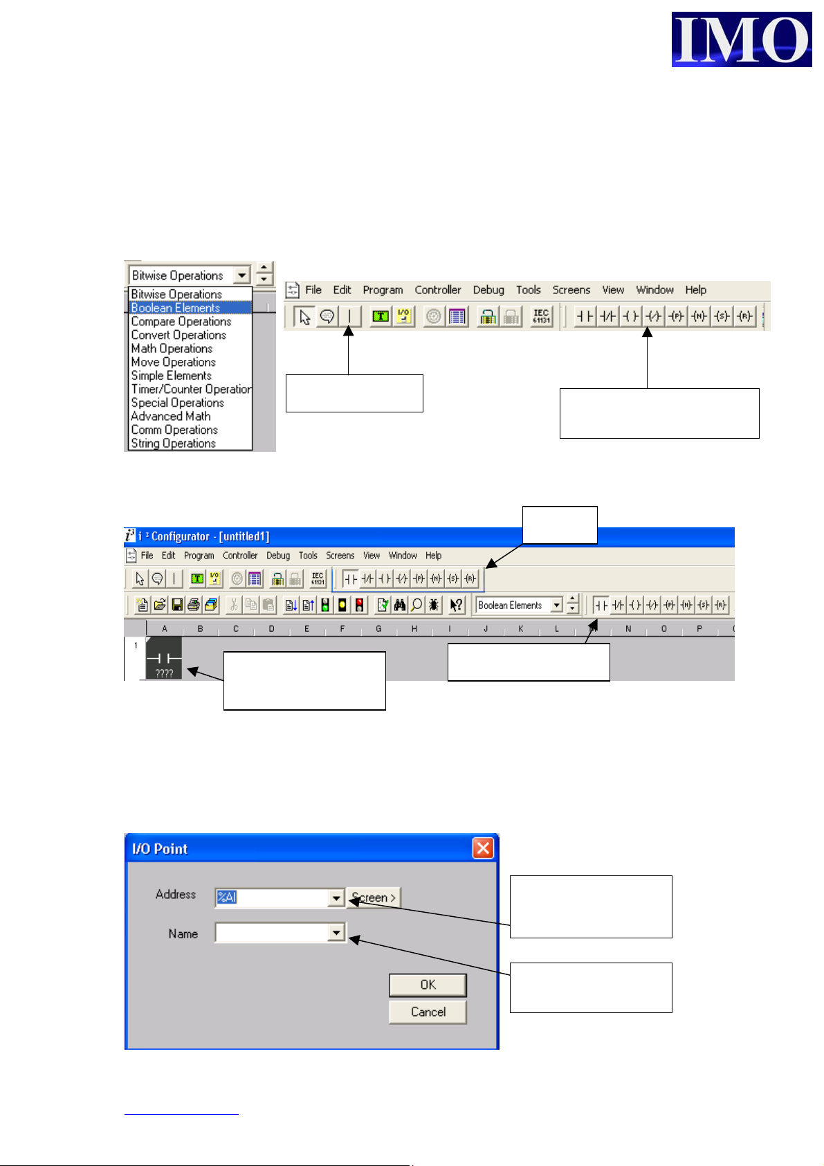
Basic Ladder Elements
All the Functions, contacts and coils for the ladder programming are contained in a
drop down menu to select what range of functions you want to insert. It is also
possible to scroll through the sub-sections using the up and down arrow keys. These
sub sections can also be docked on to the main programming interface.
Vertical line tool
Once you have selected your sub section it is now possible to click on the icon to
insert it into the ladder diagram.
Icon attaches to mouse
Enter the contact / coil / function into the diagram by clicking it into the Ladder
diagram.
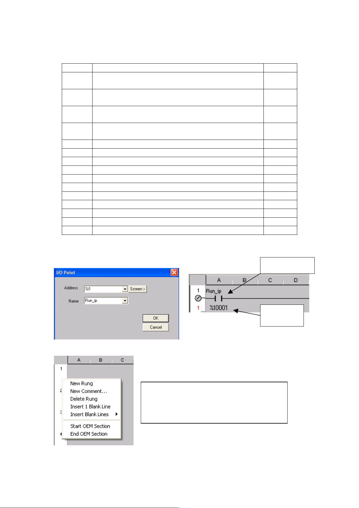
When inserting a Contact or a Coil you will need to assign the variable to a location
and giving it a name is a good idea for documentation.
for insertion into
ladder diagram
O Contact selected
Docked Boolean elements
Docked
Select from the drop
down location
Drop down menu of
redefined variables
www.imopc.com 4
Page 4
Basic Operation
n
3
i Memory Locations
Type Description and example of what might use the type Format
%I Discrete Inputs from the field; proximity sensors, panel
BOOL
buttons, etc
%Q Discrete Outputs to the field; relays, indicator lamps,
BOOL
etc.
%AI Analogue Inputs from the field; Thermocouples, WORD
4-20mA inputs
%AQ Analogue Outputs to the field; 0-10VDC or 4-20mA
WORD
outputs
%IG Global Discrete Inputs from the CAN smart I/O; BOOL
%QG Global Discrete Outputs to the CAN smart I/O; BOOL
%AIG Global Analogue Inputs from the CAN smart I/O; WORD
%AQG Global Analogue Outputs to the CAN smart I/O; WORD
%T Internal Temporary bits, use for contacts and coils BOOL
%M Internal Memory bits, use for contacts and coils BOOL
%R Internal Registers, use for timers, counters & other data WORD
%K Keypad bits, reflect Function Key status BOOL
%D Display bits, control screens or indicate screen on/off BOOL
%S Internal System Bits (See System Registers) BOOL
%SR Internal System Registers (See System Registers) WORD
Note: The allocation of I/O starts from 1 the first input is %*01 and not %*00
.
Contact name
By right clicking the mouse in the left margi
we can have some more options.
We have the options to add or remove rungs,
insert documentation and start OEM sections.
© IMO Precision Controls ltd. 5
Contact
address
Page 5
p
Input / Output Types
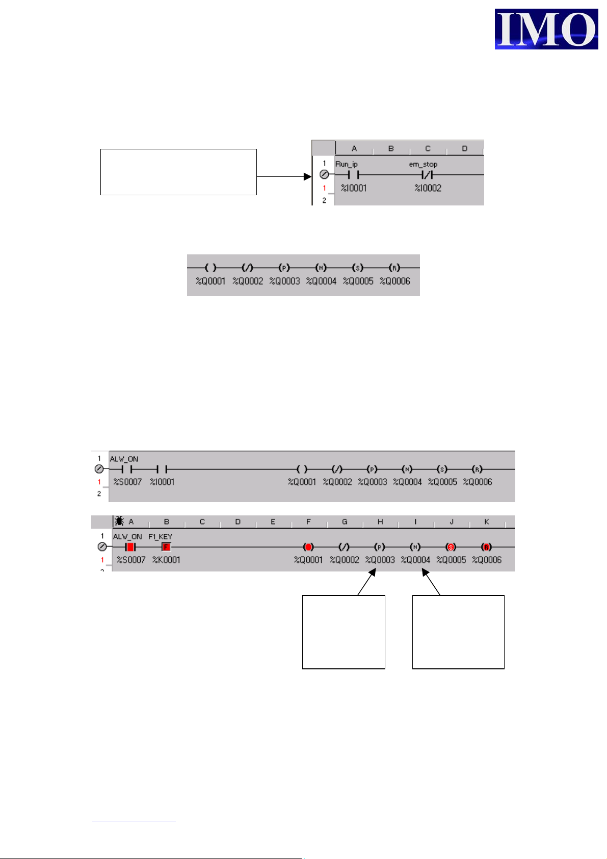
The i3 has 2 types of inputs: Normally Open (N/O) and Normally Closed (N/C).
The rung has been “Made”
when this symbol is present.
The i3 has 6 types of outputs: N/O, N/C, Positive Edge, Negative Edge, Set and Reset.
More than one output can be put on a single rung. This performs the same function as
OR’ing the outputs. When the input condition is met all of the outputs on the rung
will be activated.
Example 1:
When %I0001 is enabled, %Q0001 switches state, as does %Q0002. Whereas
%Q0003 switches on the positive edge of %I0001 and %Q0004 will switch on the
negative edge of %I0001. %Q0006 will reset from its current state.
Q3 was on
only on the
ositive edge
of the input
Q4 was on
only on the
negative edge
of the input
www.imopc.com 6
Page 6
Basic Operation
d
N
N
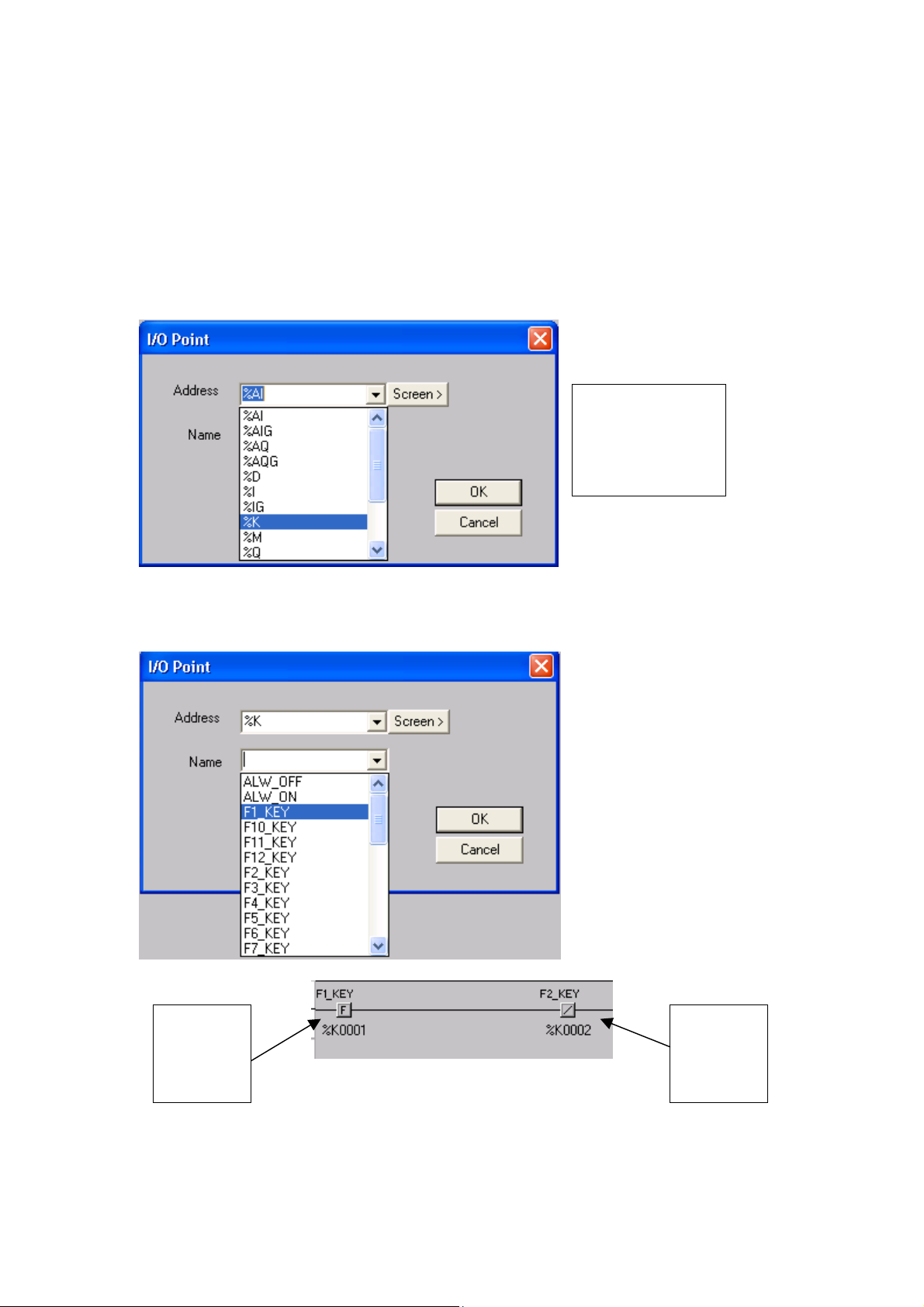
Assigning Function Keys and Screens
The i3 has 11 function keys that can be programmed into the ladder diagrams. It also
has four buttons that can be programmed through the screen editor which are
discussed later in this document.
Assigning Function Keys in the ladder diagram is very simple. Select an input contact
and address it to the Keys!
Select %K an
then assign the
address for the
key, 1-12
Or, select it by its predefined name.
O
Function
Key
contact
© IMO Precision Controls ltd. 7
C
Function
Key
contact
Page 7
n
b
a
s
n
u
n
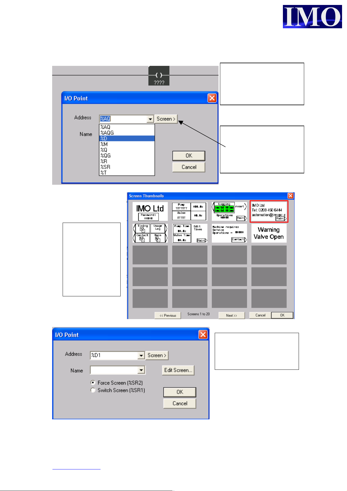
To insert a screen into the ladder logic, select an output coil and click it into the ladder
diagram.
Select %D and then enter
the number for the screen
to display, i.e. %D0001 is
screen 1.
By clicking the scree
utton you can choose
screen from the thumbnail
menu.
The screens
hown were set
up previously. If
no screen has
been set up then
it will be shown
as a blank grey
box.
We can open the scree
editor from this men
which is covered later i
this document.
There are now two options to choose from which control the way an individual screen
is presented.
www.imopc.com 8
Page 8
Basic Operation
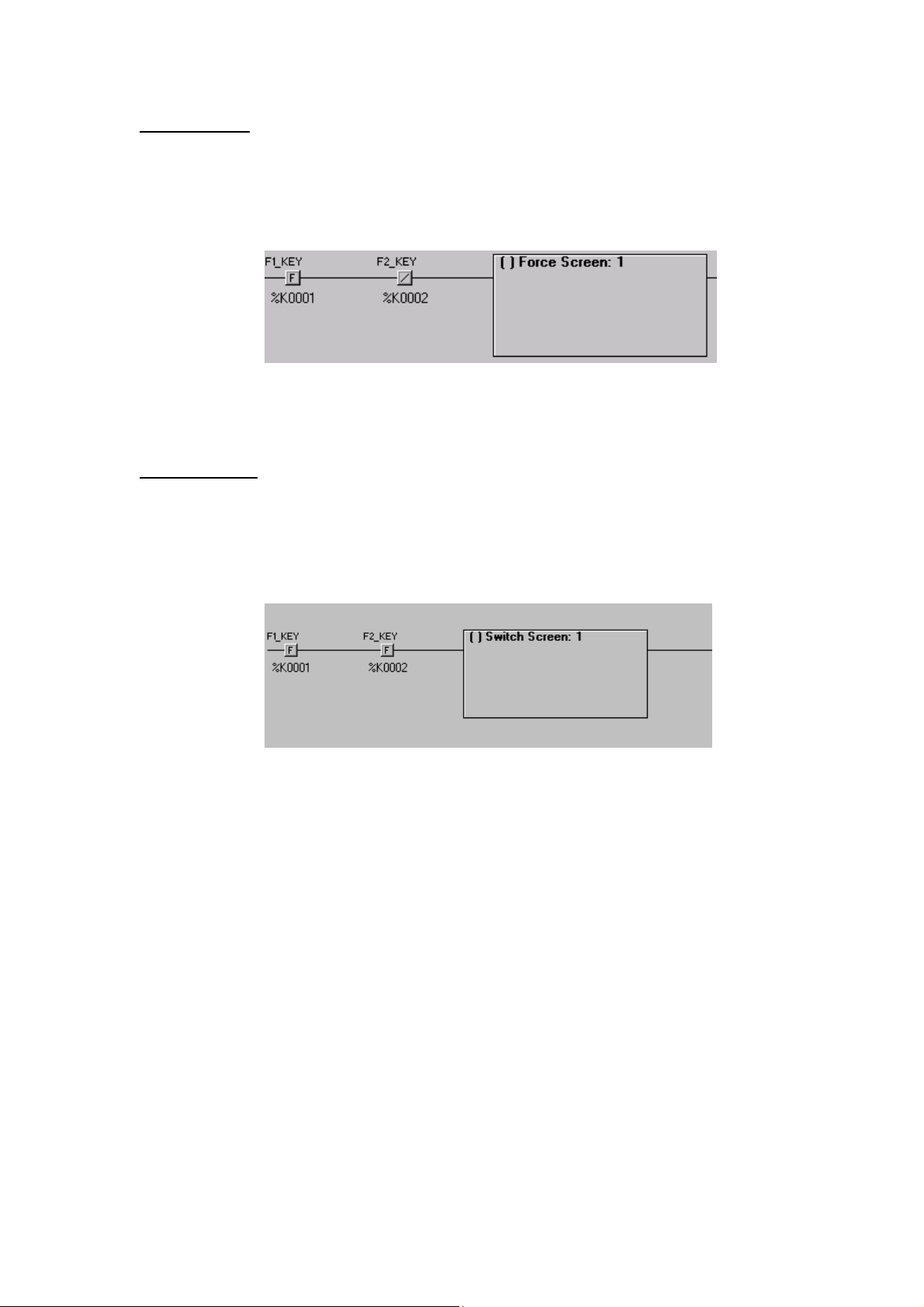
Force Screen:
Displays the screen whilst the conditions to make the contact are met. When the
condition is not met anymore the screen will go back to the previously set screen.
Example 2: Warning Message when a valve is open.
When F1_KEY AND NOT F2_KEY are pressed the i will display screen 1. When F1
3
has been released the i3 will display the previously set screen.
Switch Screen:
Changes the display to the desired screen when the condition is met.
When the logical condition is no longer true the selected screen remains on display.
Example 3: Changing screens on a menu selection.
When F1_KEY AND F2_KEY are pressed the i3 will display screen 1. When F1 has
been released the i3 Screen 1 will remain on the display until the next Screen is called.
© IMO Precision Controls ltd. 9
Page 9
n
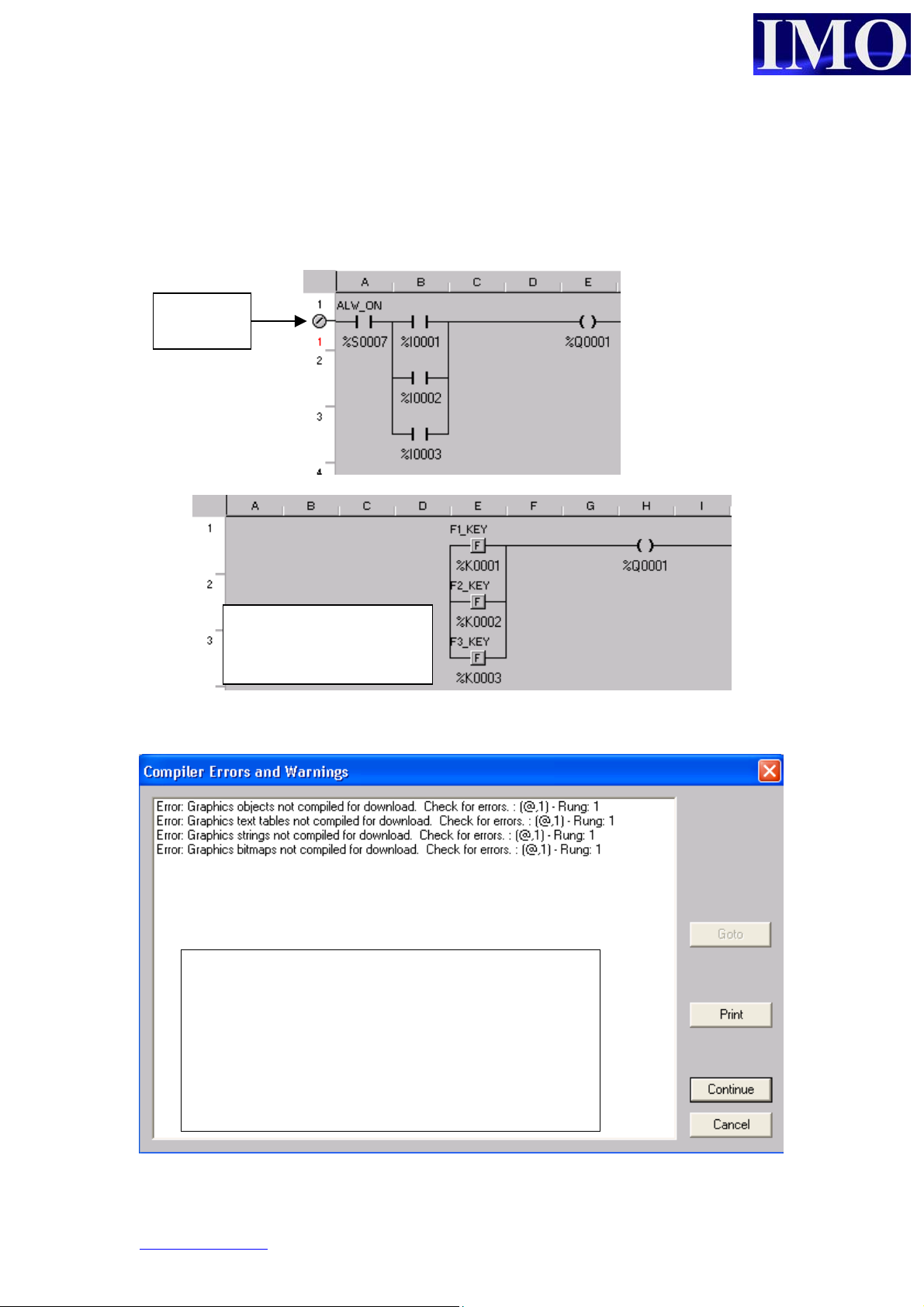
Basic Ladder Logic
Using Ladder logic it is necessary to insert a contact in the first column. A good
practice is to insert an ALWAYS ON (ALW_ON) contact at the beginning then add
your logic after.
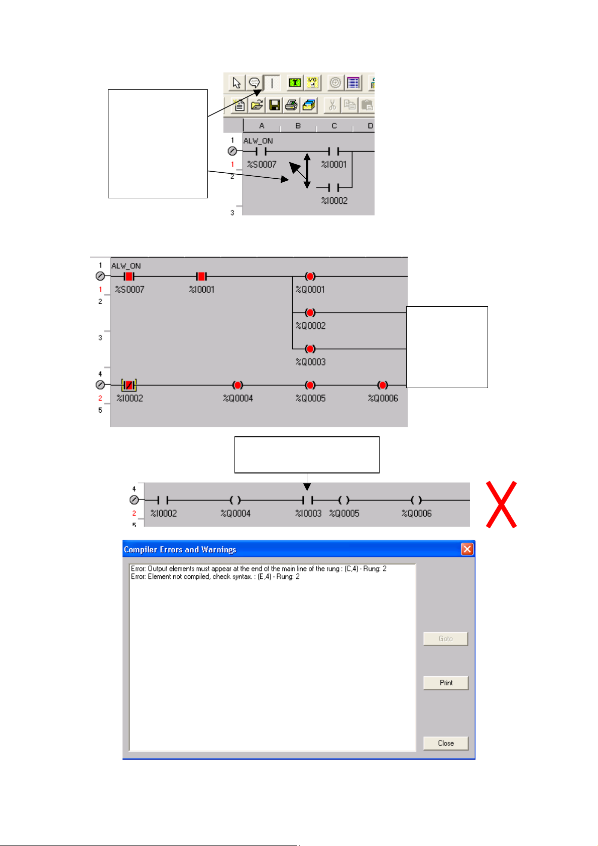
Rung is
complete
Rung not complete. The
program logic will fail to
compile and Download.
A common error message will appear if no scree
has been configured.
An initial screen must be configured before the
3
program can be successfully downloaded to the
i
www.imopc.com 10
Page 10
Basic Operation
n
N
Vertical lines
can be draw
using the tool.
The tool attaches
to the mouse
icon.
Each rung can have multiple outputs but they must be at the end of the line.
ested
outputs can
also be put
horizontally.
An input in this position
will cause an error
© IMO Precision Controls ltd. 11
Page 11
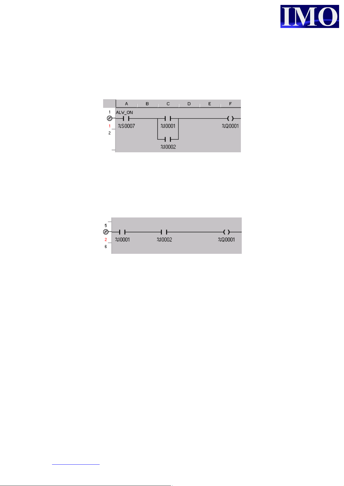
Or Gate
When any one of two or more inputs will switch on the output: In this example either
%I0001 or %I0002 will switch ON %Q01.
And Gate
When all input conditions on a single rung are met the output will switch ON. In this
example both %I0001 AND %I0002 must be on for the output %Q0001 to be
energised.
www.imopc.com 12
Page 12
Basic Operation
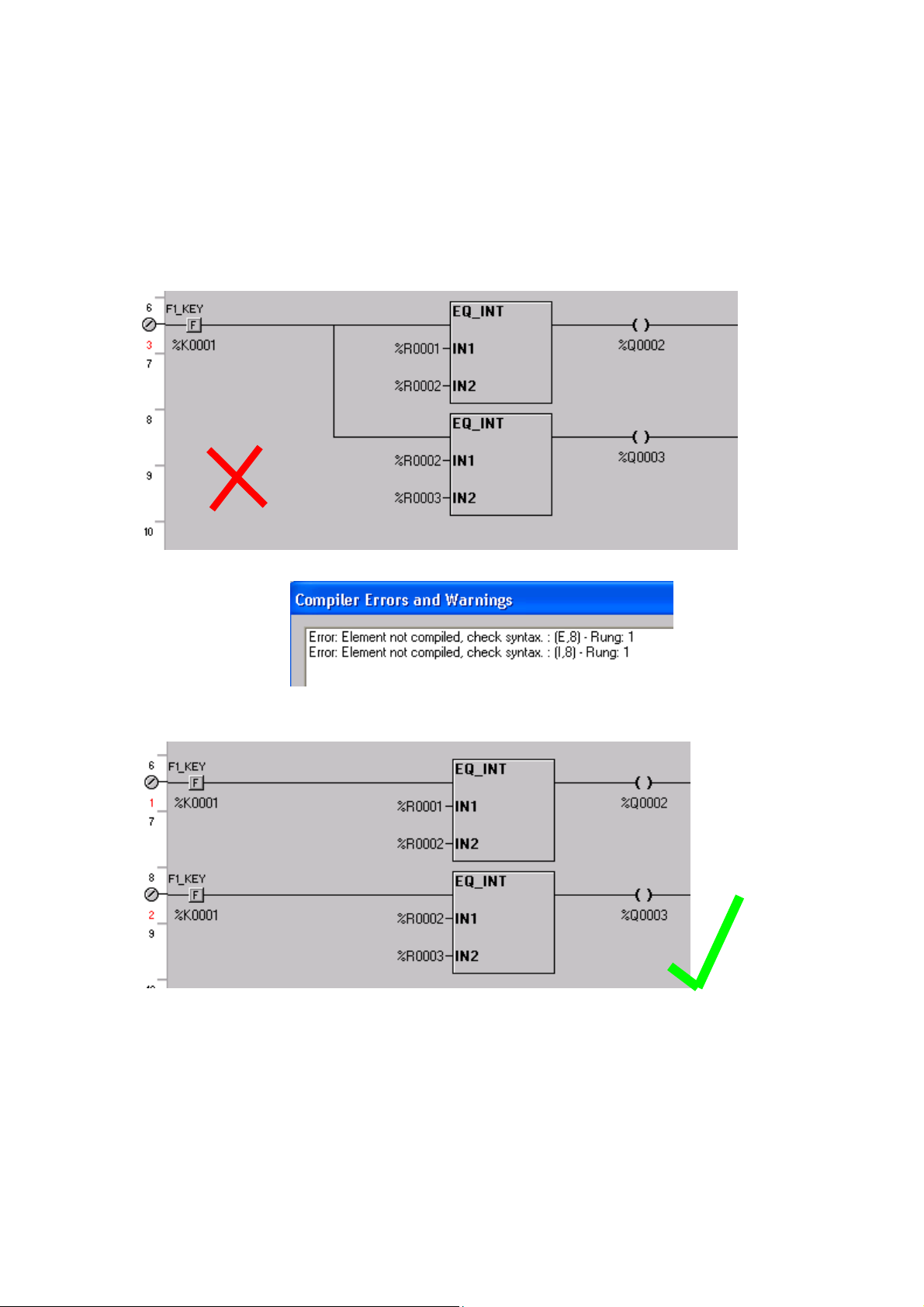
Function Blocks
All function blocks have an enable input and a Boolean output. Other I/O parameters
are dependent on the individual function block and are required to be set up when
inserting the block.
Nesting function blocks will create an error.
© IMO Precision Controls ltd. 13
Page 13
Timers and Counters
Timers and counters require two consecutive registers to store their data in memory.
The first register contains the current value and the second contains the status bits of
the counter or timer.
Register 1 = Accumulated value
Register 2 .15 = Function Enabled
Register 2 .16 = Function Completed i.e. timing elapsed, preset value met.
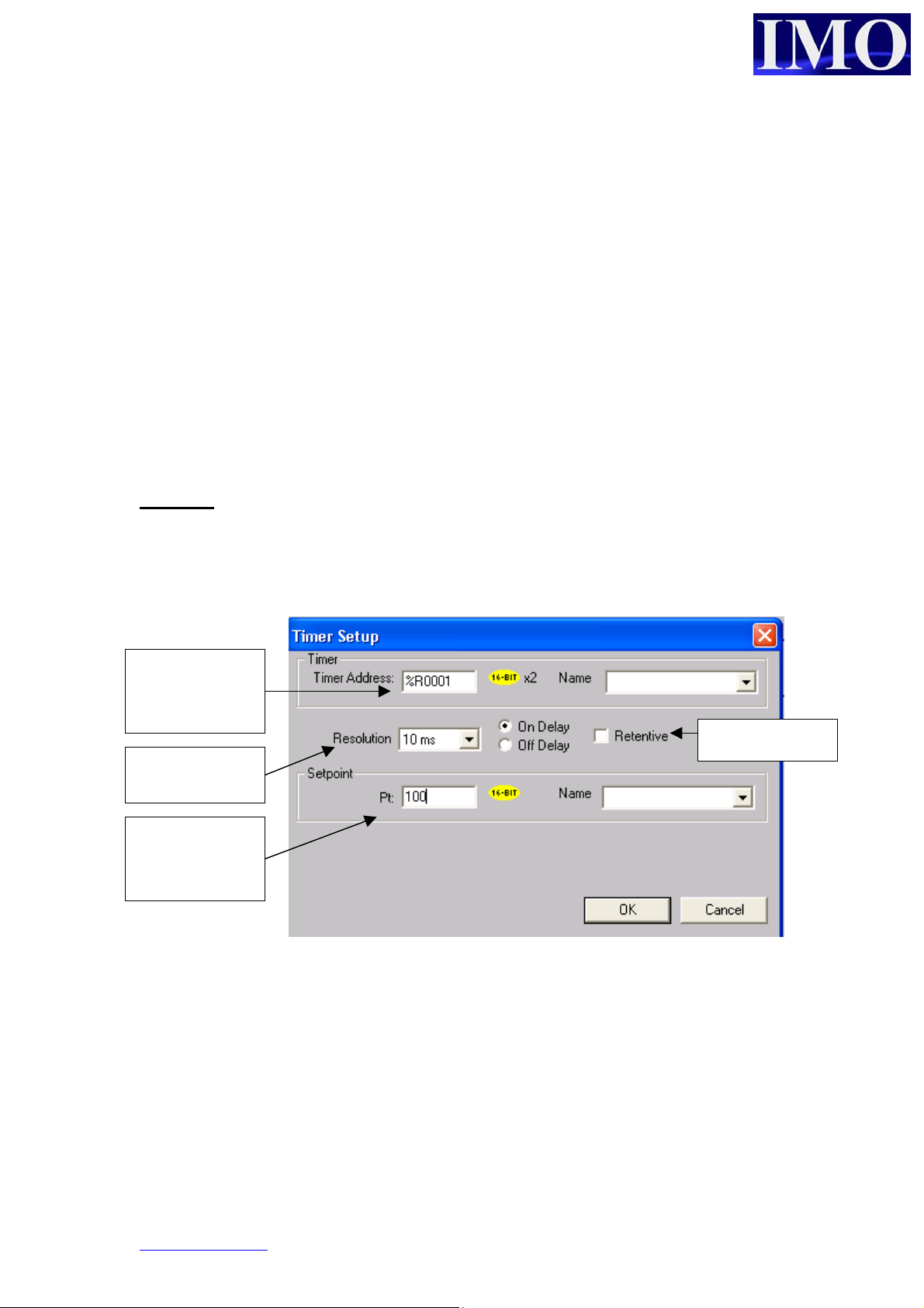
Timer Set up
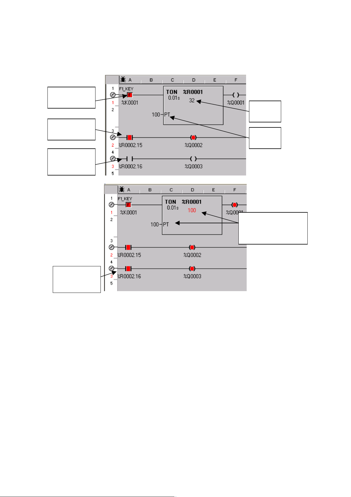
There are two types of timer, on delay and off delay. The On delay timers can be
retentive.
On Delay
Delays before the output goes high. On being enabled the timer starts. When elapsed
time reaches the Preset the output will energise. The output will remain energised
until the input to the timer has been removed.
Consecutive
registers %R01
and R02
Either 10ms or
100ms
Set point can
be a register or
a constant
Timer options
www.imopc.com 14
Page 14
Basic Operation
p
Example 4:
This is an example of a 1s On delay timer.
F1 enables
the timer
Timer
enabled
Timer is not
complete
Current
value
Preset
value
Timer output
is energised.
Current value =
reset value and the
output is high
© IMO Precision Controls ltd. 15
Page 15
p
b
f
N
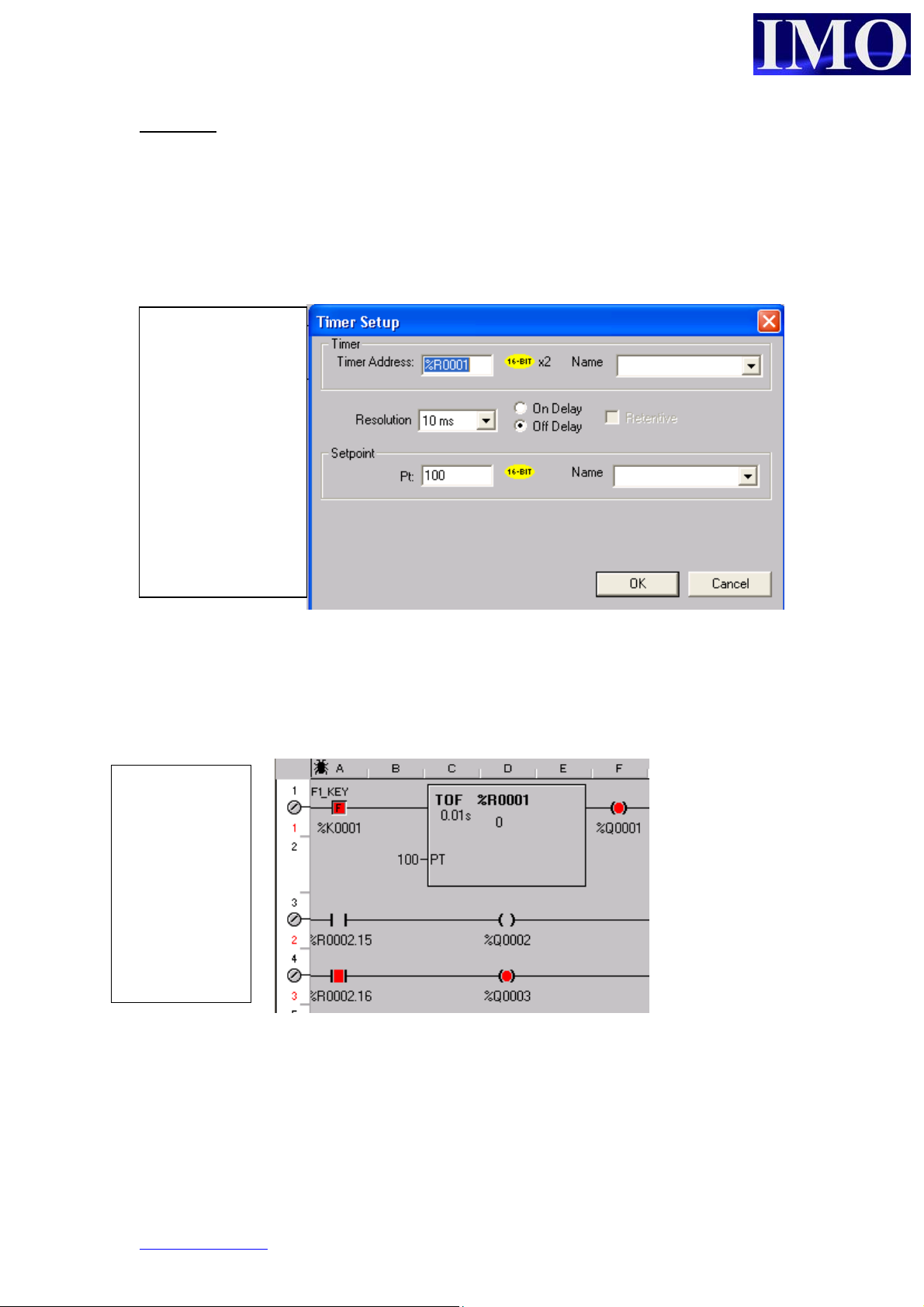
Off Delay
The Off delay timer provides a delay before switching the output off when the input is
enabled. When the input is removed the timing will begin, when the elapsed time
equals the preset the output will reset.
The setup window
is the same as the
revious example
ut the “Of
Delay” button is
checked.
otice that the
Retentive button is
no longer available
Example 5:
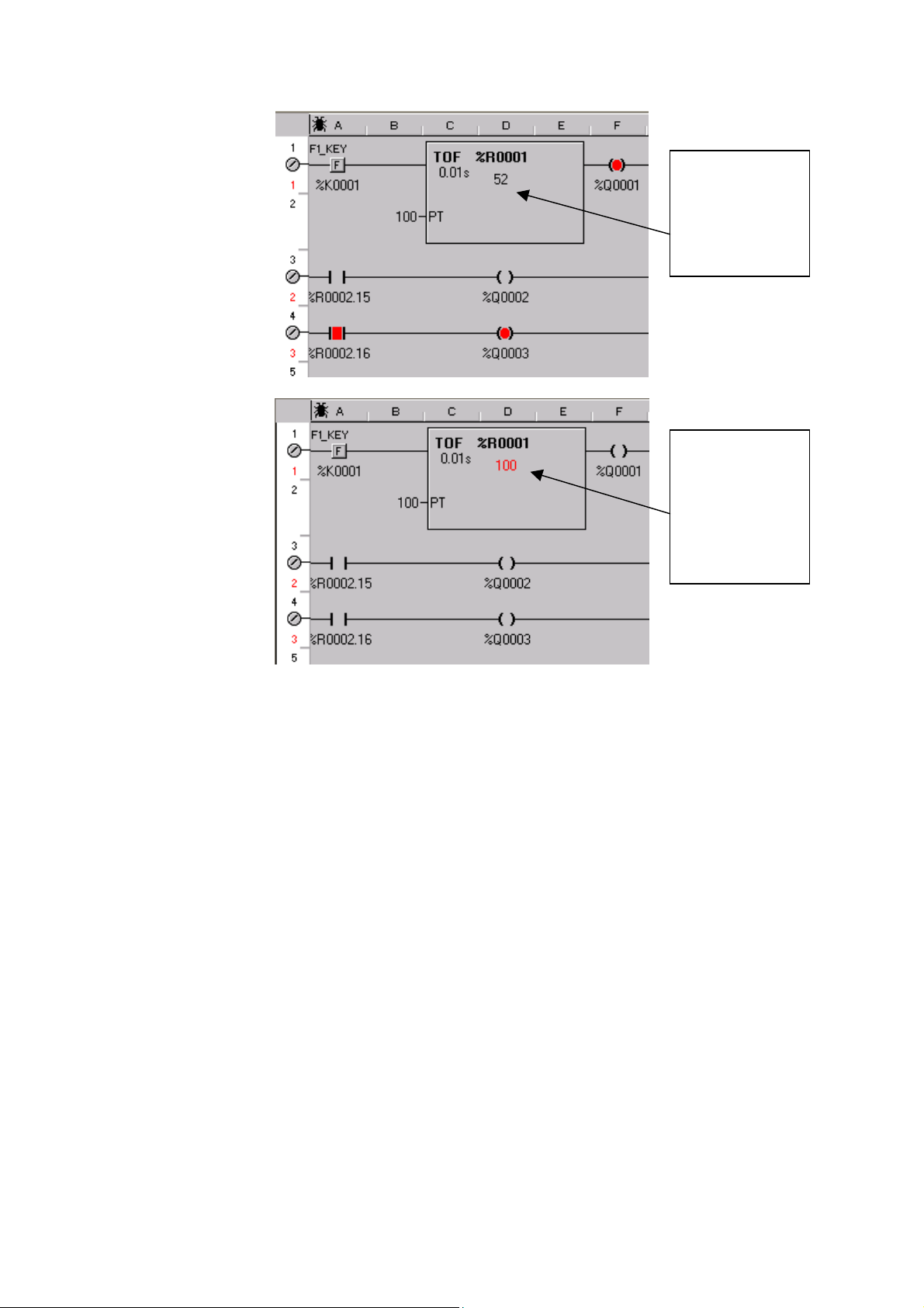
This is a 1 second Off-delay Timer. The output (%R0002.16) is energised when the
input (%K0001) is made and will remain energised for 1 second after the input is
removed.
The input to
the timer has
been enabled
and the output
is high.
When the input
is remove the
timing begins.
www.imopc.com 16
Page 16
Basic Operation
p
The output
remains high,
whilst the
current value is
accumulating.
The current
value now
equals the
reset value
and the timer is
now off.
© IMO Precision Controls ltd. 17
Page 17
p
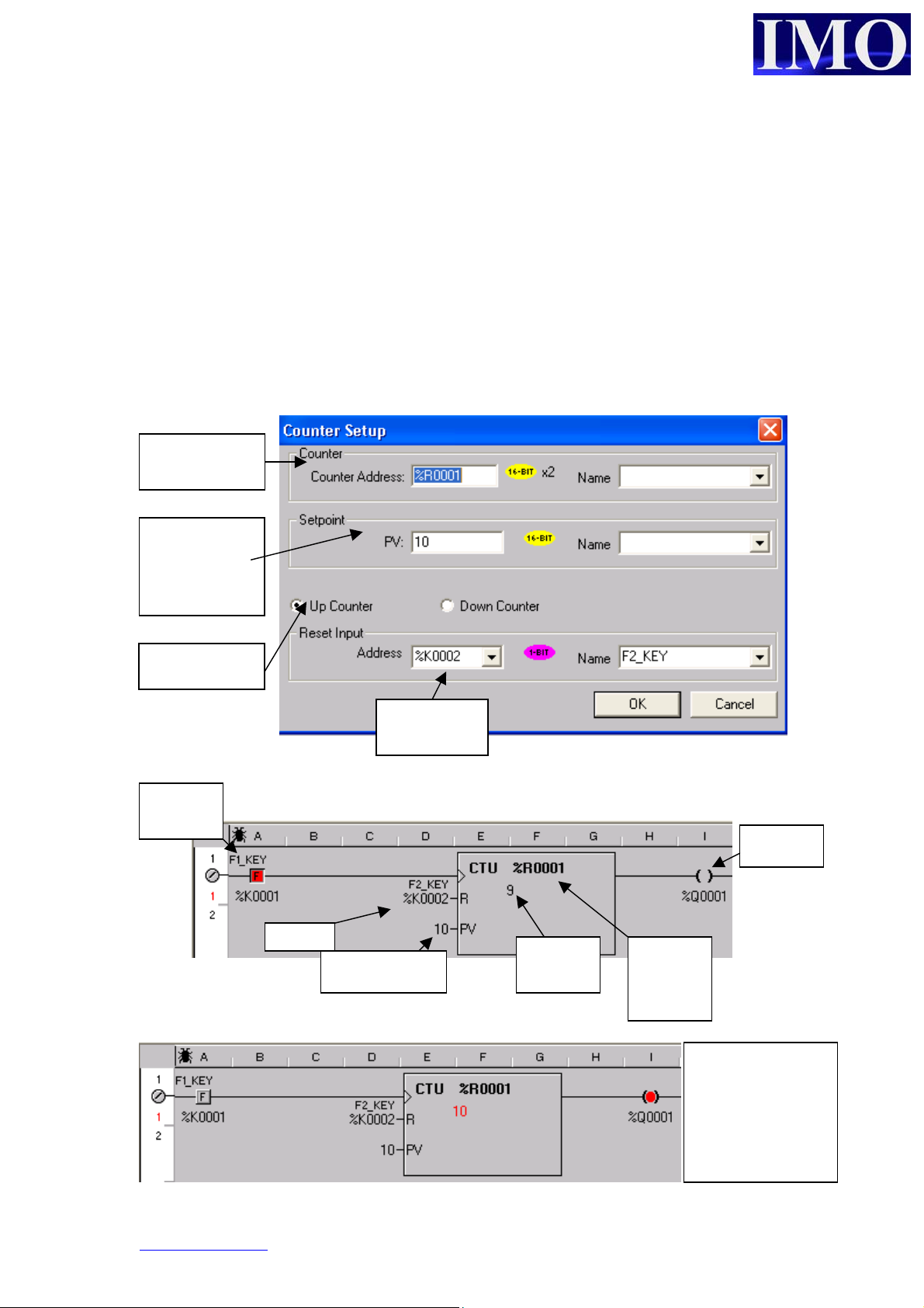
Counter Set up
There can be two types of counters, Up Count and Down Count. All the counters
increment / decrement the current value on the positive edge of a defined input and
require a Reset input.
An up counter will increment its current value from 0 to the preset value at which
point the output is energised. A down counter will decrement its current value
(starting at a value equal to the Preset) until the current value reaches 0 at which point
the output is energised. Both counters will overtake the preset if input pulses continue
to be applied to the counter after the output is energised.
Consecutive
registers (2)
Set point can
be a register
or a constant
Counter type
Input to
counter
reset
Select the
Reset input
Preset value
output
Current
value
Starting
counter
register
The count value
has reached the
reset energising
the output.
www.imopc.com 18
Page 18
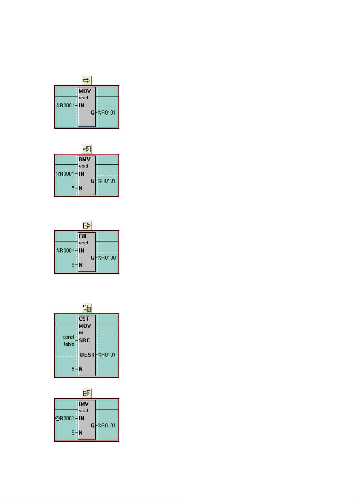
Move Functions
Basic Operation
used to copy a single byte, word or double-word from one
location to another. The count is locked at 1. In the case of the
example to the left, the value in %R1 is copied into %R101.
This only happens when the ladder rung receives power. The
value in %R101 is NOT taken back out when power is lost to
The first type of Move is the ‘Move Word’, or ‘MOV’. It is
the rung. The IN can be either a register or a constant value.
The next type of Move is the ‘Move Data Block’, or ‘BMV’.
It is used to copy a group of bytes, words or double-words to
another location. The count (N) determines how many
registers are to be copied. In the example to the left, %R1%R5 are copied into %R101-%R105. Again, this only
happens when the ladder rung receives power. The IN must be
a register reference and constant values are not allowed.
The next type of Move is the “Fill WORD”, or “Fill”. It is
used to copy the contents of a single register or value into
multiple other registers, thus filling that one value into a group
of registers. The count (N) determines how many registers to
fill that single value into. In the example to the left, the value
in %R1 is copied into %R101-%R105 so that %R101-%R105
all will have the same value in them. This can be used to zeroout a group of registers. The IN can be either a register or a
constant value.
The ‘Constant Move’, or ‘CST MOV’, it is used to move a group of
constant values into a group of consecutive registers. If, for
example, you want to move the values 1, 2, 3, 4 and 5 into %R101,
%R102, %R103, %R104 and %R105, respectively, then you can use
the Constant Move function. The count (N) is automatically
determined by how many constant values you enter into the
configuration for this function. The source data can ONLY be
constant data and cannot be register references.
The ‘Indirect Move’, or ‘IMV’, it is used to move data from variable
positions or to variable positions or both. It functions, for the most
part, like the Block Move function. If specified as Indirect, the IN
and/or the Q are used as pointers to where in the %R registers to get
data from or put data to. When looking at the ladder logic, the @
symbol will appear next to the IN or Q address if it is specified as
Indirect. This function is used in data logging applications.
© IMO Precision Controls ltd. 19
Page 19

Indirect Move Examples
In this example, the IN is specified as Indirect. This means the
controller will look at %R1 and see a value within it. If %R1 has a
value of 501 in it, the controller will go to %R501 to get the source
data. 5 registers will then be moved from %R501-%R505 to
%R101-%R105.
In this example, the Q is specified as Indirect. This means the
controller will look at %R101 and see a value within it. If %R101
has a value of 851, the controller will take the data in %R1-%R5 and
move it into %R851-%R855.
In this example, both the IN and the Q are specified as Indirect. This
means the controller will look at %R1 and see a value. Let’s say it is
241. The controller also looks at the value in %R101. Let’s say it is
341. The controller will then take the values in %R241-%R248 and
move them into %R341-%R348.
www.imopc.com 20
Page 20
Basic Operation
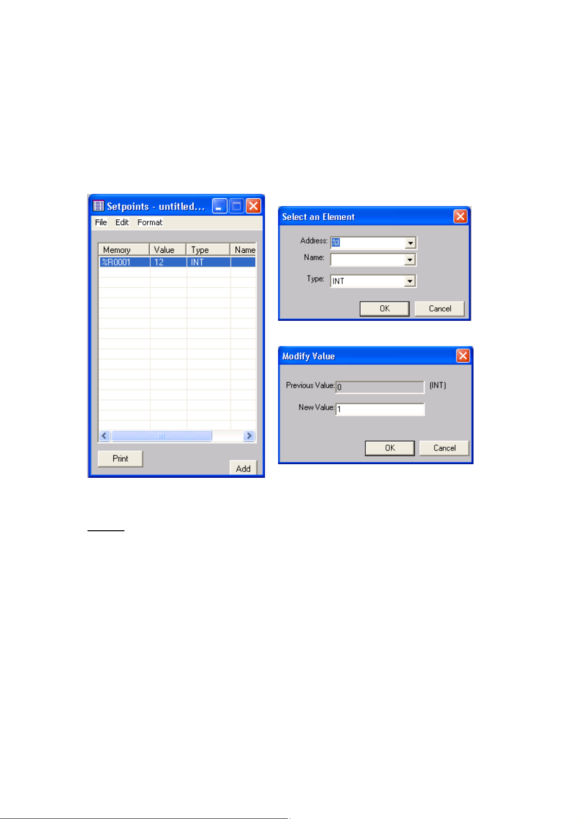
Set Points
It is possible to set registers with initial values by using the set point editor. To open
it, select the Setpoint option from the program menu.
From within the editor we can “Add” a new register. Double click on the Value
column to enter a Setpoint.
NOTE:
The Setpoint button must be selected in the Download Options when you are ready to
3
i
download the application program into the
.
© IMO Precision Controls ltd. 21
Page 21
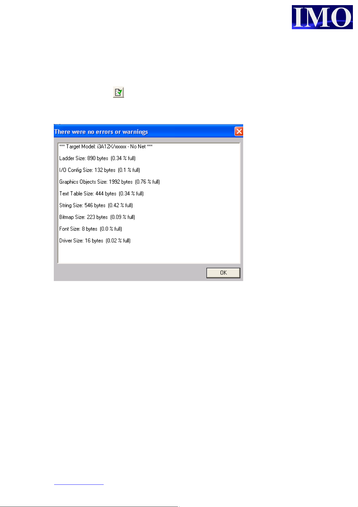
Download Options
Once you have created the Ladder logic and user screens the program can be verified
by clicking the icon . This will check the program for any errors. If there no errors
are detected in the program or configuration of the i3 the download can proceed.
Connecting to your i3
It is important to understand a little of how the
designed in order to do this correctly. The Configurator is also a complete Project
Management System capable of connecting to multiple i3 Controllers simultaneously
to debug an entire iCAN network. This means that you may have as many as 252 i3
Controllers linked together via the CAN port. Then by linking your PC via an
Ethernet, Serial, or Modem link to just one of them; you can debug and monitor them
all. So therefore, each project has the Network ID for that device stored as one of the
settings.
3
i
that does not have a CAN port, such as the basic 10A01 model, has a default
An
network ID of 253 (above the usable range of 1 – 252) as it will never be part of a
network. When creating a new project for a device without CAN the
defaults the network ID to 253. When creating a new project for a device with CAN
the software defaults the network ID to 1 – as is the default setting of a CAN enabled
3
i
. Problems can occur if a project is started with the device configured for one option,
3
i
Configurator software has been
3
i
Configurator
www.imopc.com 22
Page 22
Basic Operation
then switched to the other at a later time. The result will be a mismatch in the network
ID settings between the Configurator project and the i3 (it is trying to communicate
with ID 253 when the device is set at 1, or communicate with ID 1 when the device is
set to 253).
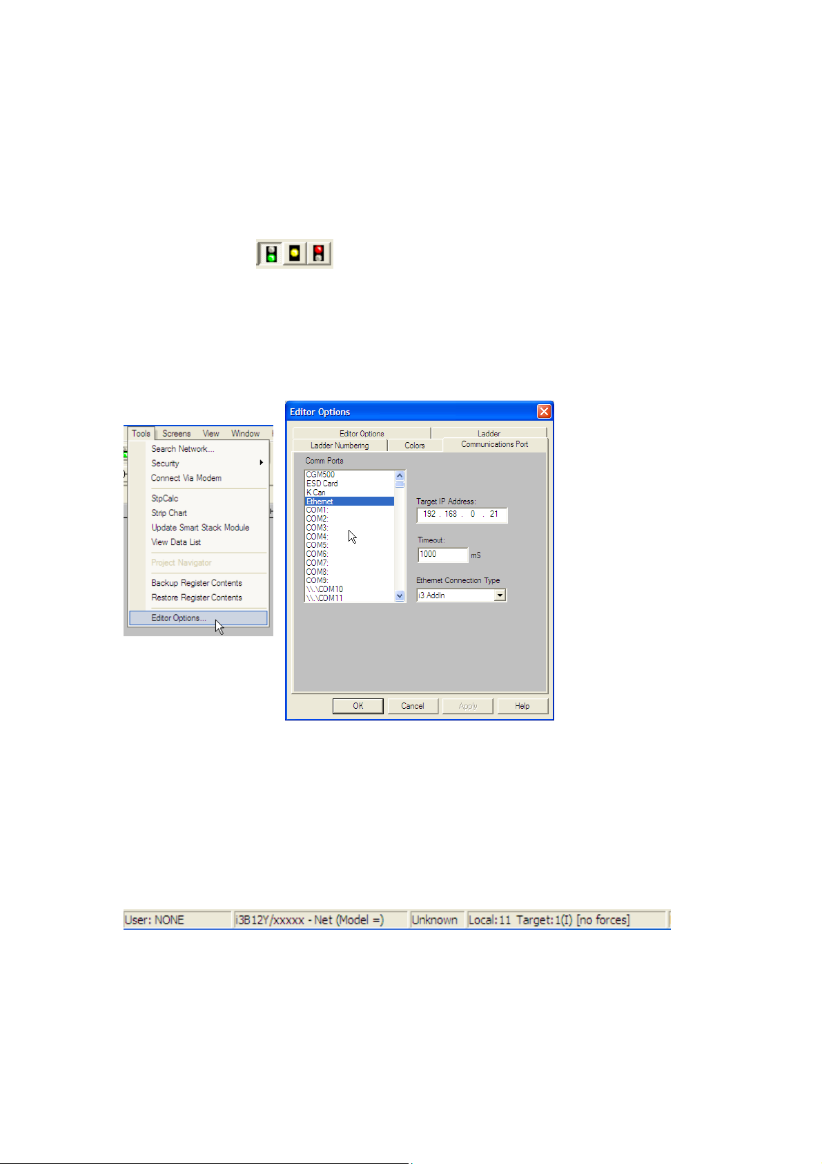
Also, the comms engine of the i3 Configurator constantly runs in the background as
soon as the software is started. The first indicator that Comms are established is that
the ‘Traffic Lights’ will show the status of the connected i3, as one of the
buttons will appear depressed.
If this does not occur then the comms settings can be verified as shown below. This
shows an Ethernet connection. Care must be taken if using a USB to Serial Adapter
that the Com port assigned to the adapters matches the one selected through these
options.
At the bottom of the Configurator screen we can see the status bar. This is showing
that we are Locally connected to the i3 of Network ID 11. This is the device that we
are physically connected to. But, it is showing the Target ID of 1. So, despite being
connected to ID 11; we are actually configuring/debugging/monitoring the i3 with an
ID of 1. It is showing us that this is an i3B model with CAN Net, but no I/O
configuration as yet (/xxxxx).
© IMO Precision Controls ltd. 23
Page 23

Configuring the correct model.
Before downloading the program it must be configured to match the model of i3 to be
used.
Select the I/O
configure from
the controller
menu.
Then click the
“Auto Config System”
button ensuring the i
3
is connected to the PC
with an i3PC45 cable.
When
configured
3
the i
part
number will
match the
unit.
www.imopc.com 24
Page 24
Basic Operation
p
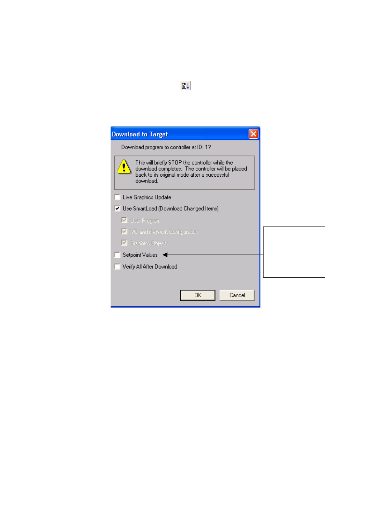
Downloading the Program
Then to download to the i3 click the icon or select Download from the Program
Menu.
The “Download to Target” menu will appear.
If you want to
download set
oints, ensure
that this option is
checked.
© IMO Precision Controls ltd. 25
Page 25
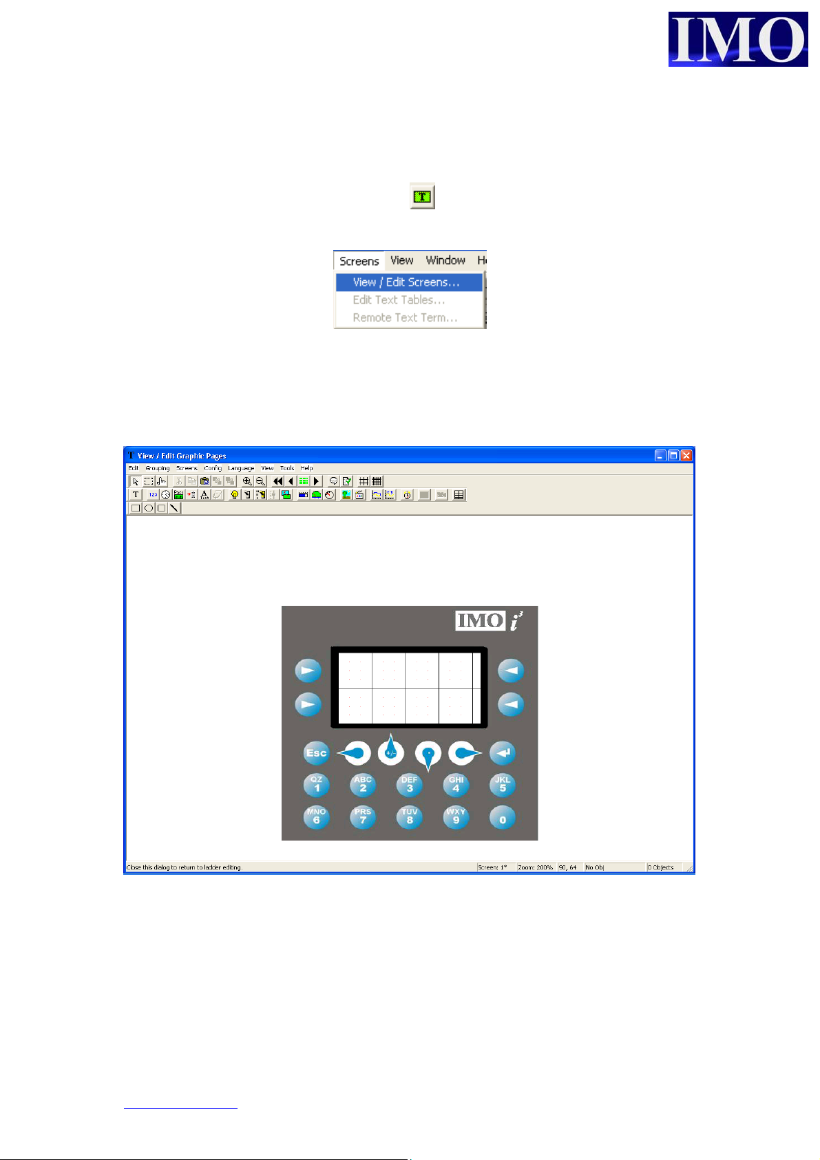
Screen Editor
To open the screen editor click on the icon or select the option from the screens
menu.
Please note that a default screen needs to be configured before a program can be
downloaded to an i3.
Before editing screens it is important to configure the I/O as previously described.
The screen editor program shows the i3 in the middle with the programming functions
at the top and screen information in the bottom right corner. To exit click the top right
corner where the X is.
www.imopc.com 26
Page 26

Screen Editor Tool Bar.
r
d
r
r
N
r
p
umeric data
Static text
RTC data
Text table
Passwor
otepad (i3B Models)
ASCII data
Menu Item
Lamp
Basic Operation
Switch & Selecto
Slider (i3B Models)
Bar Graphs, Gauges
Screen Jump
& meters
Static Bitmap
&Animation
Trends and XY Graphs
Removable Media
Alarm Handle
Menu (option)
e Edit
Reci
Selectors
Operator Stimulato
Cut, Copy,
Paste
Screen Ordering
Zoom
Scroll through
screens
View Screen
Drawing Tools
Bottom right corner of Editor
Screen
numbe
Zoom view
Cursor location
on screen in i3Object location
3
on screen in i
screen
3
umber of objects
in i
Check code
documentation
Snap to Grid lines
© IMO Precision Controls ltd. 27
Page 27
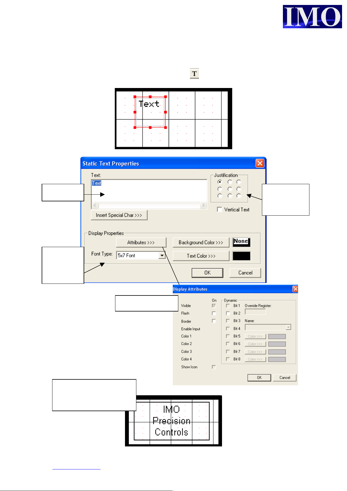
Static Text
To insert a Static Text message click on the icon and click it to the screen.
The box can be
resized as required.
To enter the text to
be displayed double
click on the box.
Insert your
text here.
Select Font
type from
the menu.
Once you have correctly
set up the static text, click
OK to confirm and exit
Display Attributes.
Justification
within the
text box
www.imopc.com 28
Page 28

Basic Operation
Numeric Data
To insert a numeric data display click on the icon and click it into the screen.
The box can be resized as
required. To Enter the
details of the numeric data
double click on the box.
The Legend of the Numeric
Field can be modified as
required.
The address of
the data to be
displayed
display
Editable
allow the
user to
enter data
through the
screen
© IMO Precision Controls ltd. 29
Page 29

R
Time Data
To insert a time data display click on the icon and click it into the screen. Double
click the box to edit the properties.
The system
time is stored
in
consecutive
SR registers
from %SR44
It may simpler to
select the RTC
registers by
choosing their S
register name
www.imopc.com 30
Page 30

Basic Operation
p
d
Password
To insert a Password display, click on the icon and click it into the screen.
The password
box is similar to
the numeric data
display but the
numbers are
hidden.
Address where the
assword will be
entered.
Simple password logic uses
a Compare Function block.
When the Password Number
entered is equal to the store
value an additional control
condition can be unlocked.
© IMO Precision Controls ltd. 31
Page 31
N
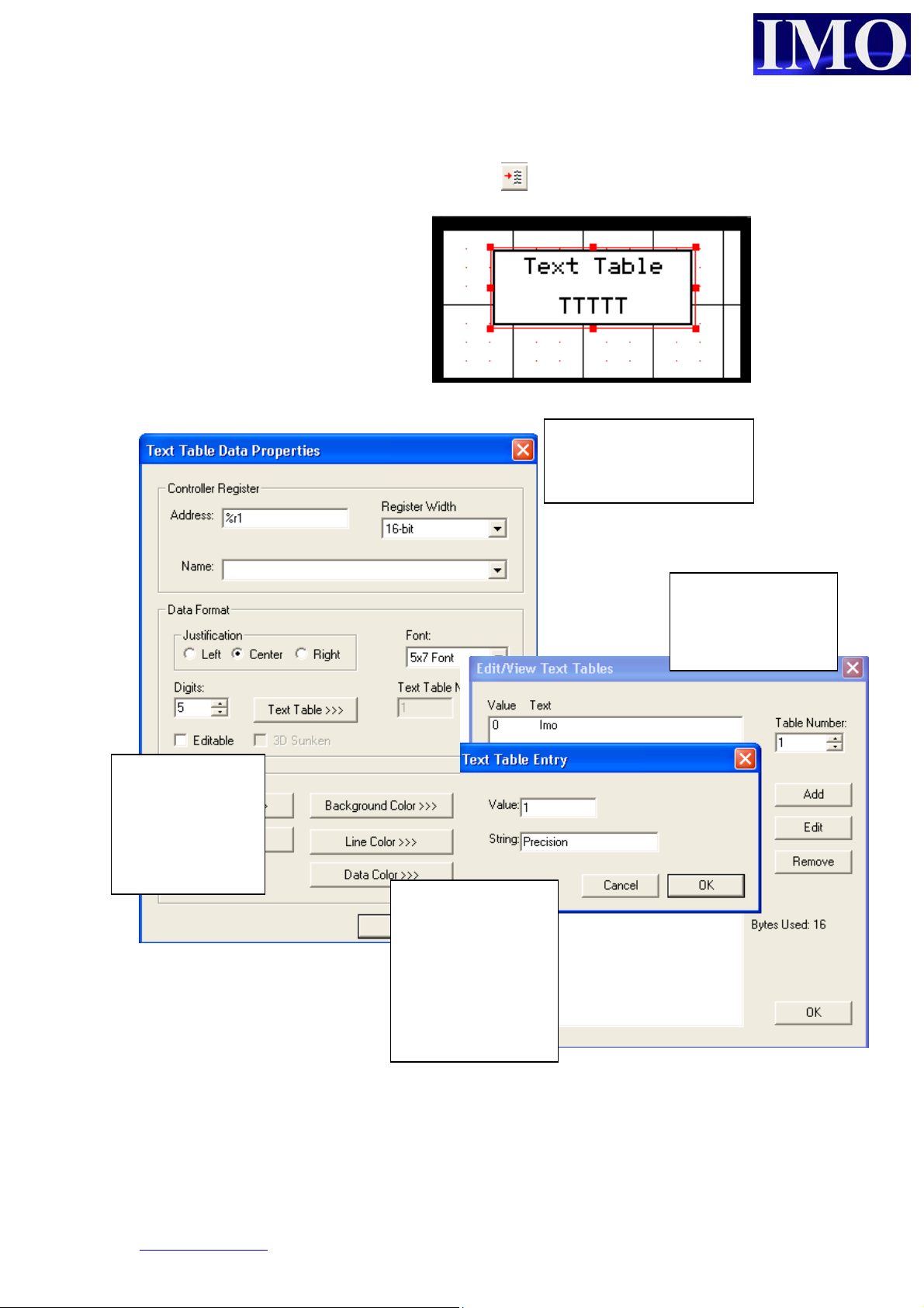
Text Table data
To insert a Text Table display, click on the icon and click it into the screen.
The text table can be used to
display text messages instead of
numeric data for a given register.
A message table can be
selected for a word, byte
or a bit.
There can be up to
255 tables and one
can be used more
than once.
The number of
digits to display
must match the
maximum length
of message to
display.
Select a value and
enter a message to
correspond to it.
ow the message
will be displayed
instead of the
numeric value.
www.imopc.com 32
Page 32
Basic Operation
N
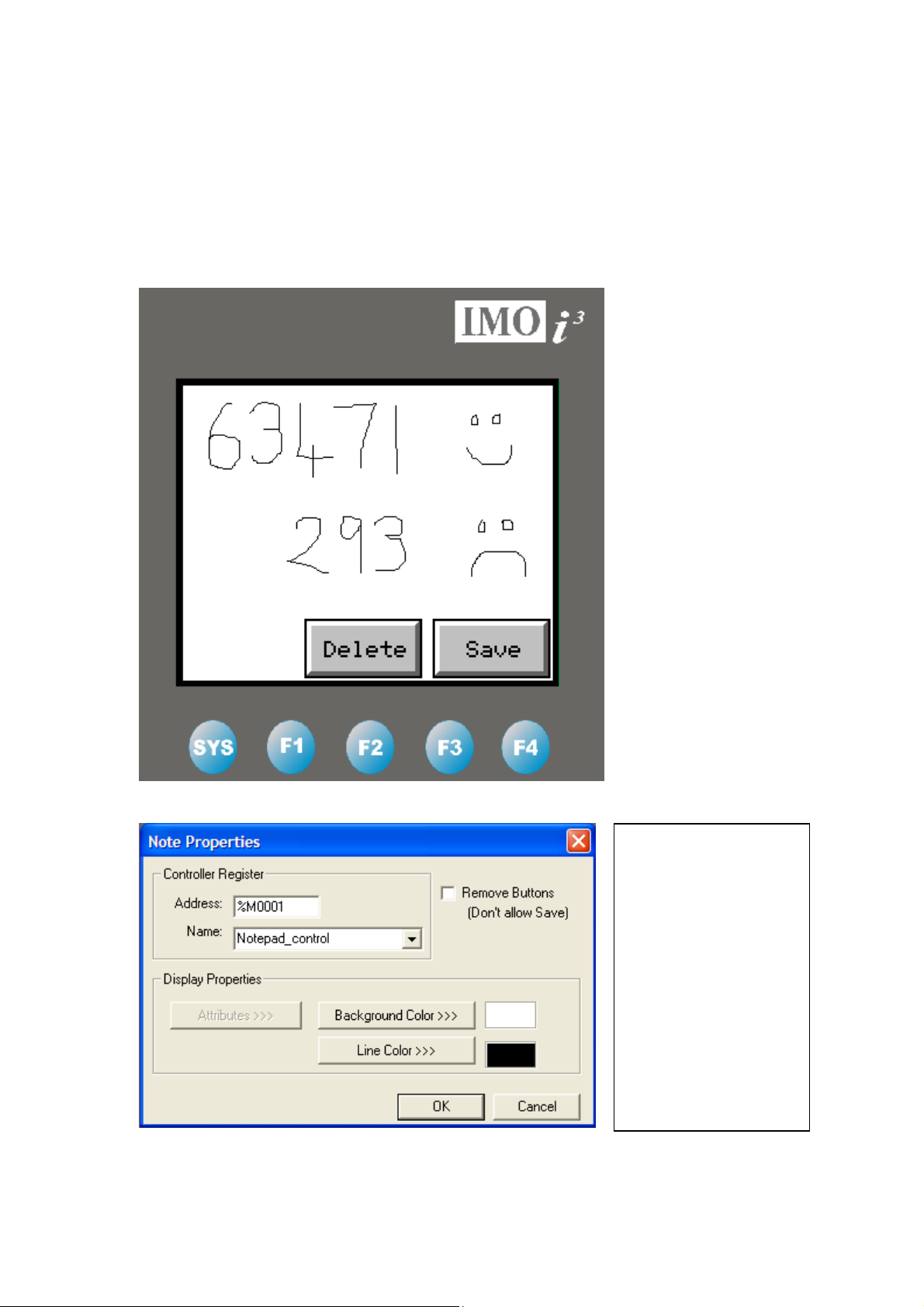
Notepad
This is function is only for touch-screen models such as the i3B12Y range. It provides
the operator with a screen upon which they can write or draw a simple diagram. This
data can then be stored into the HMI memory for recall at a later date. A useful
feature should an operator find themselves without a pen and in need of writing down
batch numbers.
The Controller
Register enables or
disables the Note
Object. The Remove
Buttons checkbox
removes the ‘Delete’
and ‘Save’ buttons
from the Note object
making sure it is
erased every time the
ote screen is exited.
© IMO Precision Controls ltd. 33
Page 33
p
i
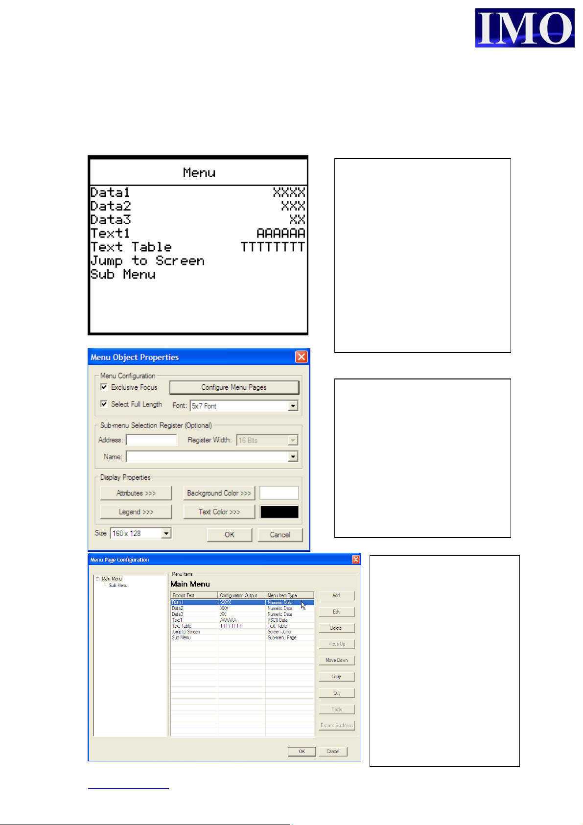
Menu Item
A Menu Item allows many settings and screens to be configured through one single
object.
Inside the Menu Item it is
ossible to easily configure
groups of Numeric Data Items,
Text Tables, ASCII text Items,
Passwords, Screen Jumps and
also Sub-menu items.
The Sub-Menus allow more pages
of configurable data to be
displayed, allowing an operator to
make many changes from within
a single screen.
The menu object is navigated via
the soft keys or touch screen.
If the Exclusive Focus is selected
then no other objects on the
screen can be activated.
Clicking on the Configure Menu
Pages button opens the window
below.
The ‘Size’ of the Menu must be
selected when using on a Touch-
3
Screen
.
Menu Items can be added,
then, configured in a similar
way to how they are outside
of a Menu Object by
specifying the Control
Register, Data Format, and
Display Properties. The
only difference is that
‘Prompt Text’ is used
instead of a Legend.
Sub-Menus can also be
added, to partition the data
into different areas as
required.
www.imopc.com 34
Page 34
Basic Operation
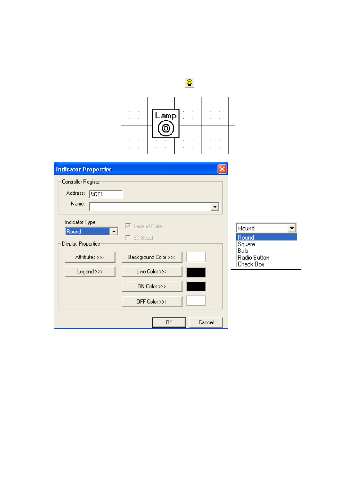
Indicator Lamp
To insert an indicator lamp, click on the icon and click it into the screen.
The indicator
lamp can only be
assigned to a bit
(Q, M, S or T).
There are several
different options for
display of lamp.
© IMO Precision Controls ltd. 35
Page 35
p
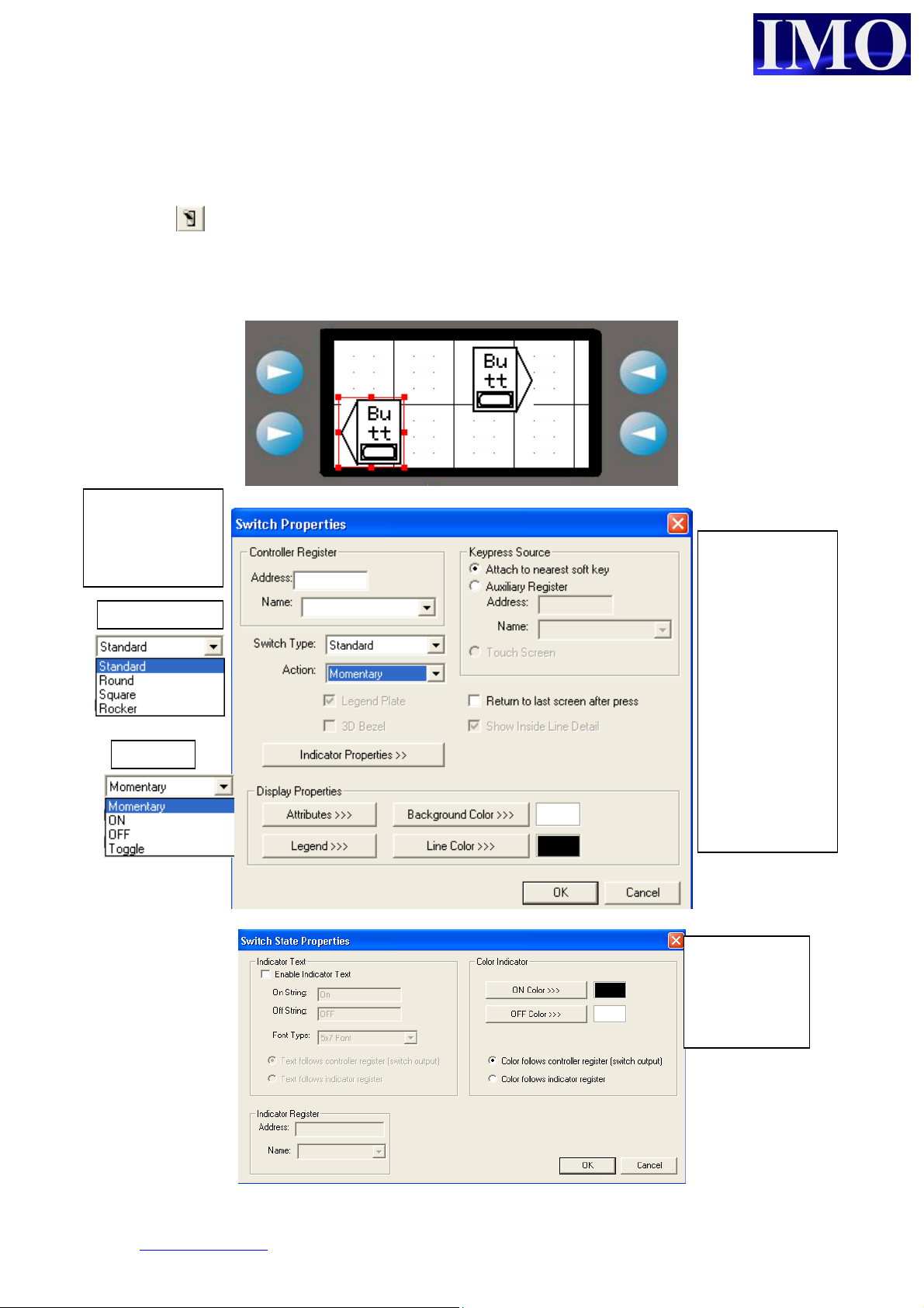
Button
There are four buttons that can be programmed through the screen editor, the
remaining keys are programmed in the ladder editor. To insert a button, click on the
icon and click it into the screen.
The button will then allocate itself to the nearest key next on the side of the screen.
Only one button can be assigned to a single key per screen.
The buttons are
binary and can
only be assigned
to a bit
Switch type
The Keypress
source defaults
at the nearest
softkey (4 keys
either side of
the screen.
However they
can be set to
another
address in the
3
i
.
We can also
edit the
indicator
roperties
www.imopc.com 36
Page 36

Basic Operation
Selector Switch
To insert a selector switch, click on the icon and click it into the screen.
It will then select the nearest buttons to it on either side of the screen. With the
selector switch the maximum the i3 can have is two positions.
A selector
switch will
be either one
of two states.
The
address
can be a
bit or a
register.
The items
can be
given
meaningful
names
© IMO Precision Controls ltd. 37
Page 37

Slider
This is an option only for touch-screen models such as the i3B12Y range. It is a quick
way to change a value inside a 16-bit register. The object can be configured with or
without extra buttons for fine control, and automatically changes it orientation from
horizontal to vertical depending how it is sized – similar to the Bar Chart Item.
The Slider has configurable
scale limits. It also has two
checkboxes that allow the
graphic of the slider to be
turned off along with the
Inc/Dec buttons.
www.imopc.com 38
Page 38

Basic Operation
Screen Jump
Screen jumps are allocated like buttons but are for jumping between screens in a
menu fashion. To insert a screen jump, click on the icon and click it into the
screen.
The jump
button will
allocate itself
to the nearest
key at either
side.
Select what screen number to jump to and the display properties of the button.
The Keypress
source defaults
at the nearest
softkey (4 keys
either side of
the screen.
However they
can be set to
another
address in the
i3 or can even
be selected
using the
cursor and
arrow keys
© IMO Precision Controls ltd. 39
Page 39
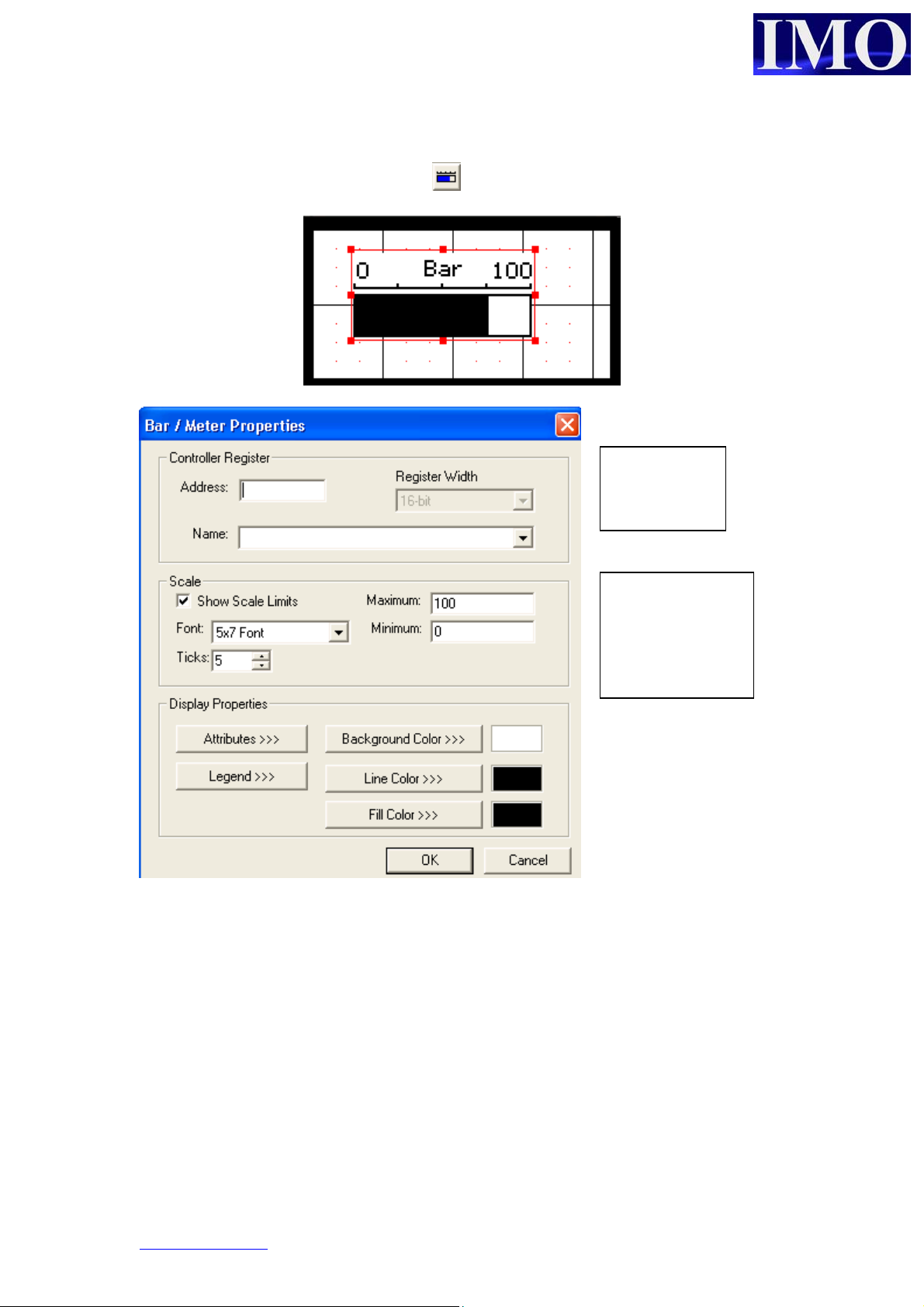
Bar Graph
To insert a bar graph, click on the icon and click it into the screen.
To graphically display
a register value on the
screen. Click on the
edge of the box and
drag to make the bar
graph bigger.
The bar
graphs must
be a word.
The bar graph
has to be scaled
and this can be
shown on the
screen.
www.imopc.com 40
Page 40
Basic Operation
b
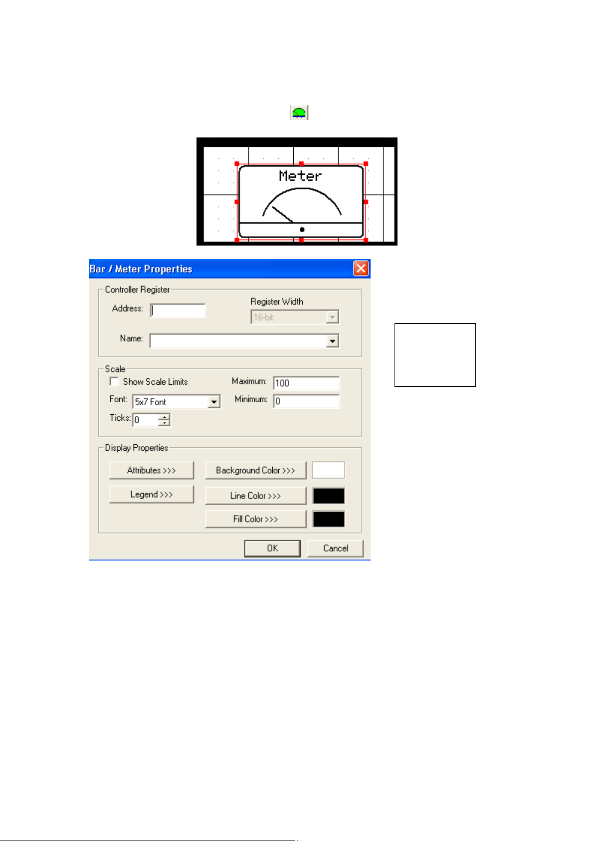
Meter
To insert a meter graph, click on the icon and click it into the screen.
Another option
to the bar
graph is o
display the data
as a meter.
The details
are the same
as with the
ar graph.
© IMO Precision Controls ltd. 41
Page 41
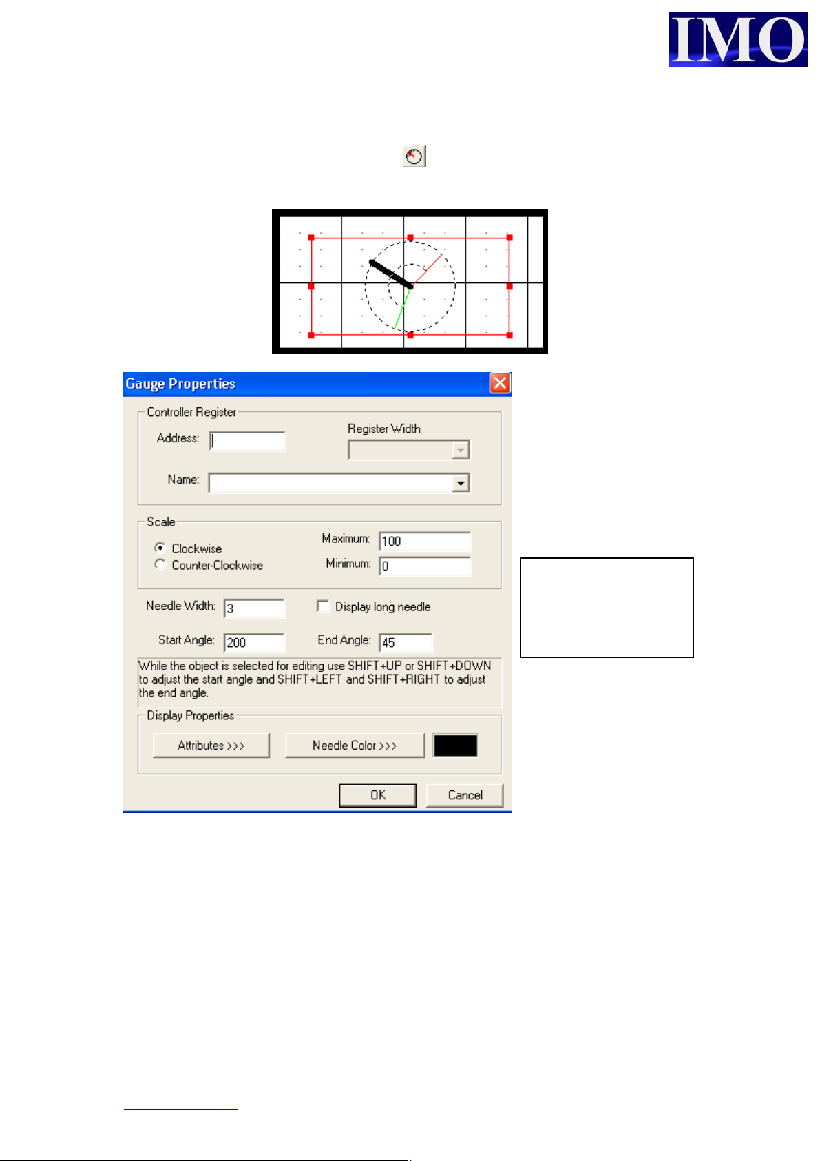
p
Gauge
To insert a gauge graph, click on the icon and click it into the screen.
The Gauge is more
complex than a bar /
meter. This gauge is
an automotive style
gauge and can be
laced over bitmaps.
Select starting and
ending angle and the
needle will rotate
within the set scale.
www.imopc.com 42
Page 42

Basic Operation
Static Bitmap
A bitmap can be used as a screen back drop, where a company logo can be inserted.
To insert a static bitmap, click on the icon and click it into the screen.
The i3 has a
mono screen,
therefore the
bitmap must
comply to these
restrictions.
Bitmaps can be created in simple packages like MS Paint.
© IMO Precision Controls ltd. 43
Page 43
b
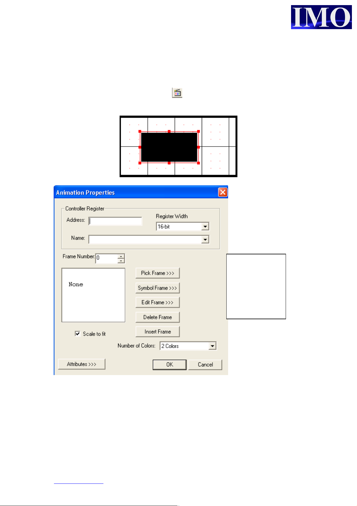
Animation
The animation displays a series of bitmaps depending on the value of a register,
double word, word, byte or bit.
To insert an animation, click on the icon and click it into the screen.
Select the
bitmaps for the
frames to match
the value in the
registers, i.e. a
it will have two
frames.
www.imopc.com 44
Page 44

Basic Operation
p
Trend
The data trend tracks data over a period of time. To insert a trend, click on the icon
and click it into the screen.
A data trend can
track up to four
registers over a
set period of
time.
The sample can be in
seconds, minutes or
hours
The trigger address
is required to
activate the trend.
The trend can be 1 of
4 different types, see
the help file for
detailed information
Up to 4
ens per
trend can
be edited.
i.e. 4 data
registers.
The axis titles
can be edited
to something
more
meaningful,
and the scale
can be adjusted
© IMO Precision Controls ltd. 45
Page 45

p
p
X – Y Data Graph
To insert an X – Y Graph, click on the icon and click it into the screen. The X-Y
graph represents variation of a variable in comparison to variations in one or more
variables.
The trigger
address is
required to
reset and
refresh the
lotting
rocess.
www.imopc.com 46
Page 46

Basic Operation
Alarms
To insert an Alarm Log, click on the icon and place it into the screen. There are
two types of alarm: Summary and History. Summary only displays the alarm when it
is currently active and History logs the alarm. There are two steps to setting up the
alarm, first the button needs to be set up then the log itself.
The alarm will
display a
message and
time stamp it
for when it
occurred.
Type of
alarm log
Details to
display
There can be
up to 16
different
alarm groups
© IMO Precision Controls ltd. 47
Page 47

Configure the Alarm Log
Select Alarm from
the Config Menu
drop down, to open
the Alarm Log
editor.
The alarm
trigger can
be 1
register or
consecutive
Choose what
to display in
the History
log
www.imopc.com 48
Alarm
message to
display and
group
related to.
Page 48
Basic Operation
q
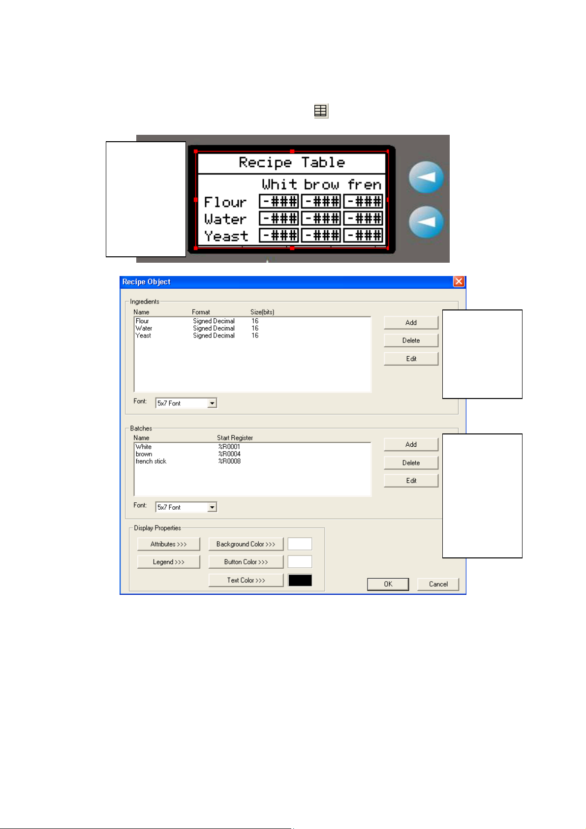
Recipe Editor
To insert a Recipe Editor Object, click the icon on to the screen.
A recipe can
be created to
store the
values of
variables for
different
batch
uantities.
Add the
ingredients
table. These
will be stored
in consecutive
registers.
Add the
different
batches, to
store the
different
rates of
ingredient
quantities
© IMO Precision Controls ltd. 49
Page 49

p
Set up the
ingredient
display and
scales.
Add the
batch
roperties
and storage
register.
This recipe function can be used in conjunction with move function blocks, to move
recipe data from one location to another.
www.imopc.com 50
Page 50

Basic Operation
© IMO Precision Controls ltd. 51
 Loading...