

Page 1
GW-7552 PRIFIBUS/MODBUS GATEWAY
Quick Start User Guide
1. Introduction
This manual introduces the GW-7552's basic setting and operating quickly, the user
can refer to the user manual in the ICP DAS companion CD-ROM (Path:
“CD:\PROFIBUS\Gateway\GW-7552\ manual\GW-7552 user manual.pdf”).
This manual helps users to understand about the GW-7552 module and application.
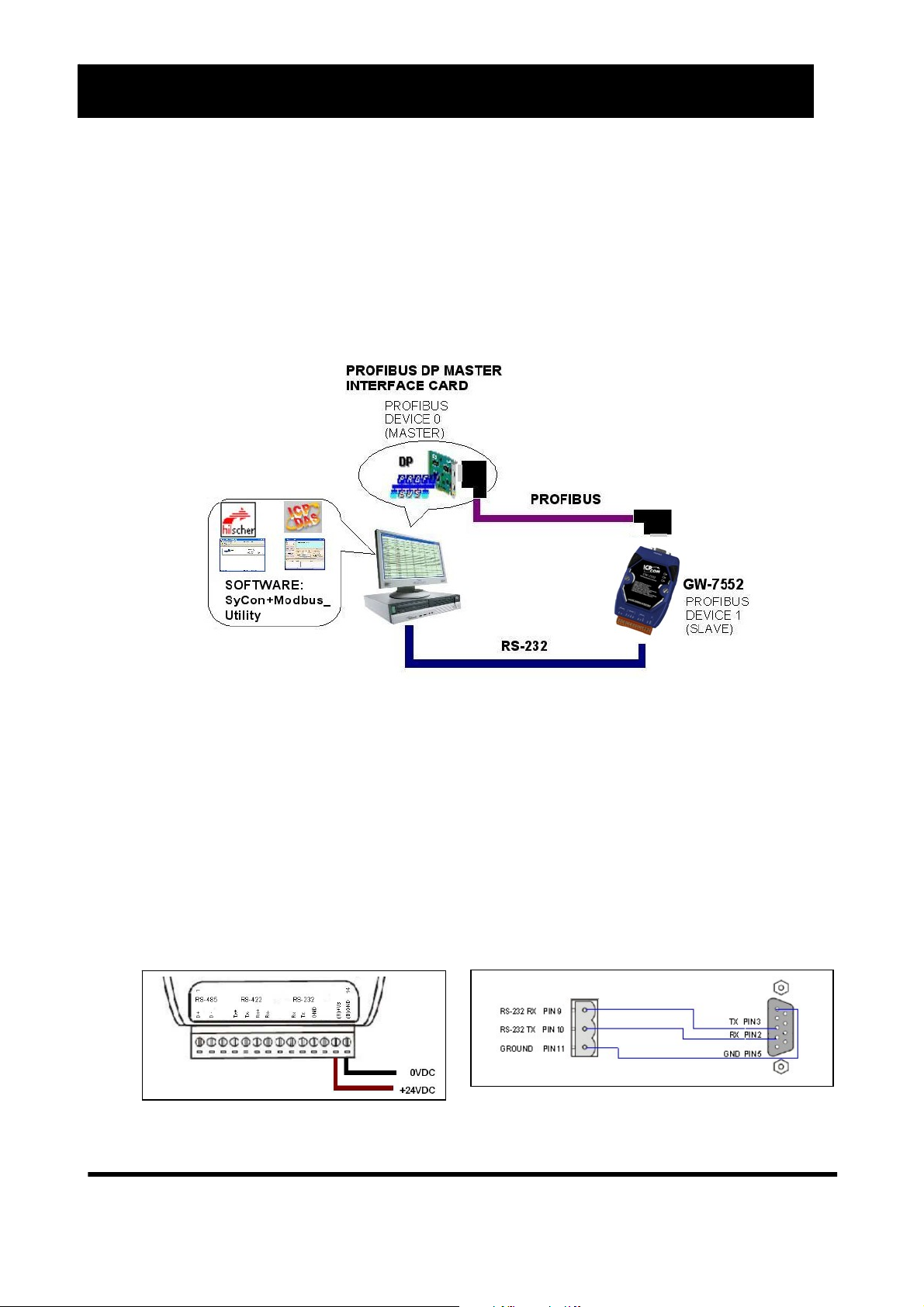
In the following examples the CIF50-PB PROFIBUS master card from Hilscher is
used. The configuration and communication is done by the program “SyCon”
provided by Hilscher.
Application example of PROFIBUS to Modbus
In this example the GW-7552 acts as a Modbus slave device. When the GW-7552
module receives a write DO Modbus command from PC’s COM Port, the GW-7552
module can send the message to the input data area of PROFIBUS master station.
When the GW-7552 module receives a read DI Modbus command from PC’s COM
Port, GW-7552 module can refer to the output data area of PROFIBUS master
station to produce response message and send it to PC’s COM Port.
2. Hardware configuration
RS232 connection Power connection
GW-7552 PROFIBUS/MODBUS GATEWAY Quick Start User Guide (Version 1.30) PAGE:1
Page 2
PROFIBUS connection
Here we recommend users to use the standard PROFIBUS cable and
connector (DB9 male). It is only needed to use D-type connector via
PROFIBUS cable to connect PROFIBUS master station and GW-7552
module. PROFIBUS master station and GW-7552 module belong to terminal
equipments in this example, thus we need to enable the terminator resistor in
the D-type connector.
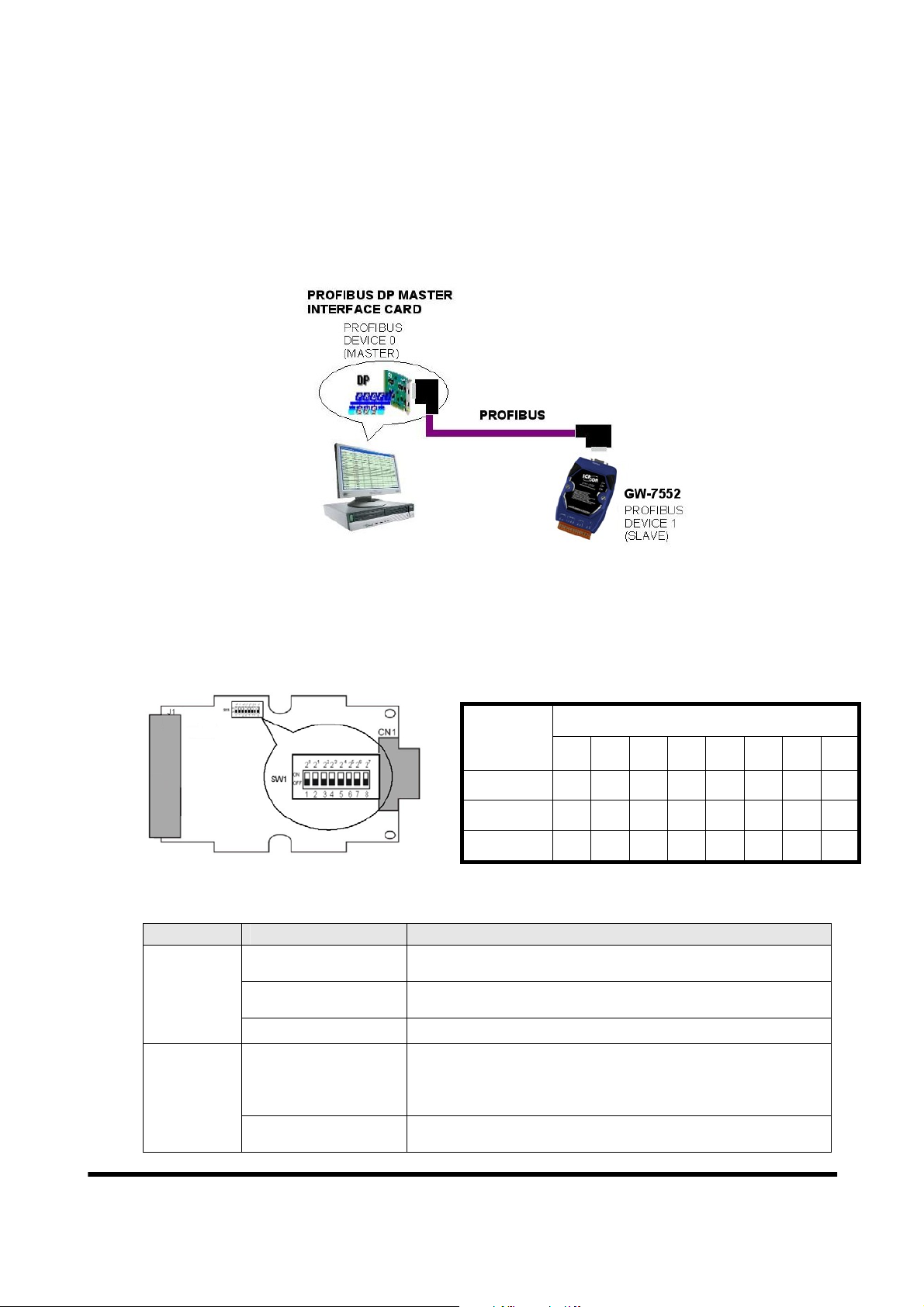
Address setting
The GW-7552 is a slave device of PROFIBUS DP protocol. The station address
of GW-7552 can be set by dip switch. The dip switch can be seen by open the
cover, as shown in the below. The range of dip switch is 0~126, here we set
GW-7552 module’s dip switch to 1.
Station
address
1 2 3 4 5 6 7 8
1 1 0 0 0 0 0 0 0
10 0 1 0 1 0 0 0 0
31 1 1 1 1 1 0 0 0
DIP SWITCH(SW1)
LED status indicator
LED Status Description
When the GW-7552 is as a Modbus slave device and receiving
query message form Modbus master device, PWR led will flash.
Power supply is ok.
The firmware has loaded.
When the GW-7552 connects with the utility tool, it will flash
fast (flash once about 55ms).
When the GW-7552 has diagnostic message, it will flash slowly
(flash once about 220ms).
The connection is error with PROFIBUS master device or
PROFIBUS system configuration is not correct.
PWR
ERR
flash
on
off Power supply has failed.
flash
on
GW-7552 PROFIBUS/MODBUS GATEWAY Quick Start User Guide (Version 1.30) PAGE:2
Page 3
PROFIBUS system configuration is correct.
It is normal operation.
Data exchange mode.
It is normal operation.
RUN
off
on
off GW-7552 module is not in data exchange mode.
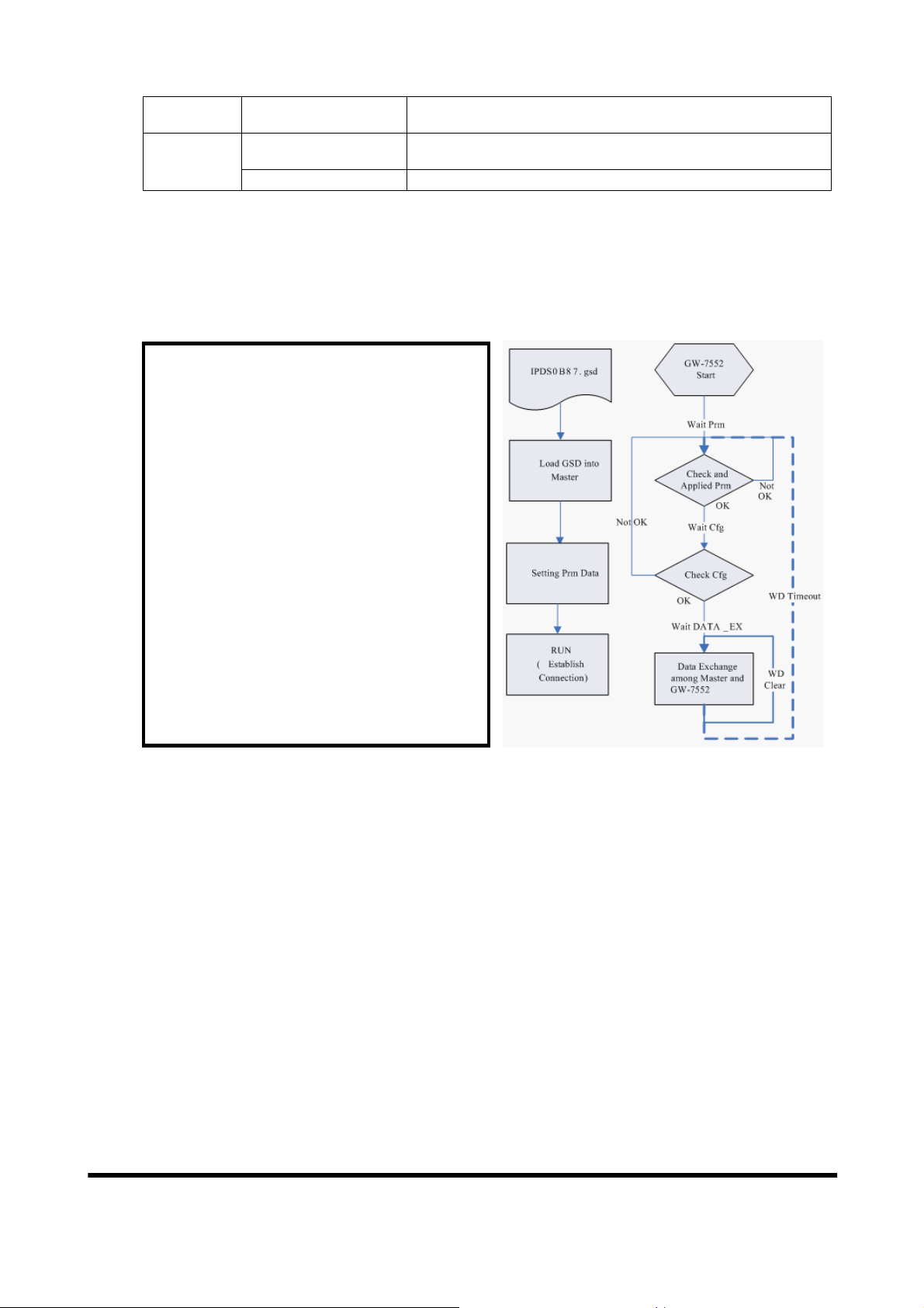
3. Establish connection with GW-7552
Before establish the connection between DP-Master and GW-7552, users
should obey the following steps first.
1. First, users must load the
electronic device description file
(GSD file) of the GW-7552 into
the DP-Master.
2. And then set the parameters and
configurations.
3. Finally change your DP-master
from offline state to operate
state. The GW-7552 will be
initialized. If there is no error
occurs, GW-7552 proceeds into
data exchange state. At the
meantime, if there is any error
occurs, GW-7552 will return to
wait for parameterization.
4. Software configuration
GSD file
Please copy the GSD file (IPDS0B87.gsd) and the Bitmap file (ICP_7552.
bmp, i_7552.bmp) from the CD of the GW-7552 module into the Profibus
configuration tool.
File->CopyGSD
(Directory: --> CD:\PROFIBUS\ GATEWAY\GW-7552\GSD\)
¾ the example of how to load GSD file
Here, we use the hilscher CIF50-PB PROFIBUS communication interface to
show how to load GW-7552’s GSD file step by step.
GW-7552 PROFIBUS/MODBUS GATEWAY Quick Start User Guide (Version 1.30) PAGE:3
Page 4

Step 1: Click insert slave button
g
in the PROFIBUS
confi
uration tool.
Step 2: Choose GW-7552 device
and click Add button.
Step 3: Set address of GW-7552
and then click OK button.
¾ Set the parameters of the GW-7552
The user just needs to change Modbus type to slave and use the default
value in the other parameters in this example. Please refer to user manual
section 4.3 The Configuration of the common parameters.
Double click the GW7552’s icon to enter the
Slave configuration dialog
Step 4: Finish adding GW-7552
in the DP-master
Click <Parameter Data>
button to enter the Parameter
Data dialog
GW-7552 PROFIBUS/MODBUS GATEWAY Quick Start User Guide (Version 1.30) PAGE:4
Page 5

b
g
g
Change Modbus type to
slave and click <OK> button
¾ Set the modules of the GW-7552
The modules of the GW-7552 are described below.
● System setting module:3 byte out
● Output module:Output Relay/CoilÆ 1~32 Bytes
Output RegisterÆ 1~64 Words
● Input module:Input Relay/CoilÆ 1~32 Bytes
Input RegisterÆ 1~64 Words
In this example, we configure a “system setting module”, an “Output
Relay/Coil--2 Byte module” and an “Input Relay/Coil--2 Byte module”, as
follows.
Double click GW-7552’s icon to
enter Slave confi
uration dialo
Configure module and click OK
utton
GW-7552 PROFIBUS/MODBUS GATEWAY Quick Start User Guide (Version 1.30) PAGE:5
Page 6

When the user finishes the configuration and saves setting in the
PROFIBUS master station successfully, the 'RUN' LED indicator of GW7552 is turned on. That shows the GW-7552 working in the data exchange
mode.
Click <Online->Download> to download the setting into PROFIBUS master
station
5. GW-7552 module communication test
This demo uses utility “MBRTU” on the PC to communicate with the GW-
7552. The User can download it on the web site:
http://ftp.icpdas.com.tw/pub/cd/8000cd/napdos/modbus/modbus_utility/
settings of the “MBRTU” are shown in the below.
. The
MBRTU setting
GW-7552 PROFIBUS/MODBUS GATEWAY Quick Start User Guide (Version 1.30) PAGE:6
Page 7

¾ PROFIBUS input test
--Send Command to write DO of the GW-7552
The user needs to input command (” 01 0F 00 00 00 10 02 FF FF”) here and
click <Send Command> button to send Modbus command and then MBRTU
can receive response message (” 01 0F 00 00 00 10 54 07”). The user can find
byte 0, 1 of input data area of Profibus master device have changed into “FF”
at this time, as shown in the below.
Send modbus command (output data: FF, FF)
Receive “0xFF” in input data area of Profibus master station
Module Byte Data type Representation Value
Input module
¾ PROFIBUS output test
--Send Command to read DI of the GW-7552
The user needs to input command (” 01 02 00 00 00 10”) in MBRTU and
click <Send Command> button to send Modbus command and then MBRTU
can receive response message (” 01 02 02 00 00 B9 B8”). In this message, the
user can know the value of DI0 & DI1 is “0” in the GW-7552.
--Send output data to write DI of the GW-7552 by the Profibus master
Input 0 Byte Hex 0xFF
Input 1 Byte Hex 0xFF
The user needs to set “0xFE” & “0xDC” in byte 3 & byte 4 of output data
GW-7552 PROFIBUS/MODBUS GATEWAY Quick Start User Guide (Version 1.30) PAGE:7
Page 8

area of Profibus master device and then set the value of the first byte from 0
to 1 to trigger the data output command.
--Send Command to read DI of the GW-7552 again
Now the user can input command (” 01 02 00 00 00 10”) in MBRTU and
click <Send Command> button to send Modbus command again. Then
MBRTU can receive response message (” 01 02 02 FE DC F8 41”). In this
message, the user can know the value of DI0 & DI1 have changed into
“0xFE” & “0xDC” in the GW-7552, as shown in the below.
Set output data and trigger output data command
Module Byte Data type Representation Value
System
module
Output
module
Output 0 Byte Hex
Output 1 Byte Hex 0x00
Output 2 Byte Hex 0x00
Output 3 Byte Hex
Output 4 Byte Hex
0x00 → 0x01
0x00→ 0xFE
0x00→ 0xDC
Send Modbus command to read DI of the GW-7552 and receive data (0xFE, 0xDC)
GW-7552 PROFIBUS/MODBUS GATEWAY Quick Start User Guide (Version 1.30) PAGE:8
 Loading...