

Page 1
GW-7433D
MODBUS TCP Server/CANopen Master
Gateway
Quick Start User Guide
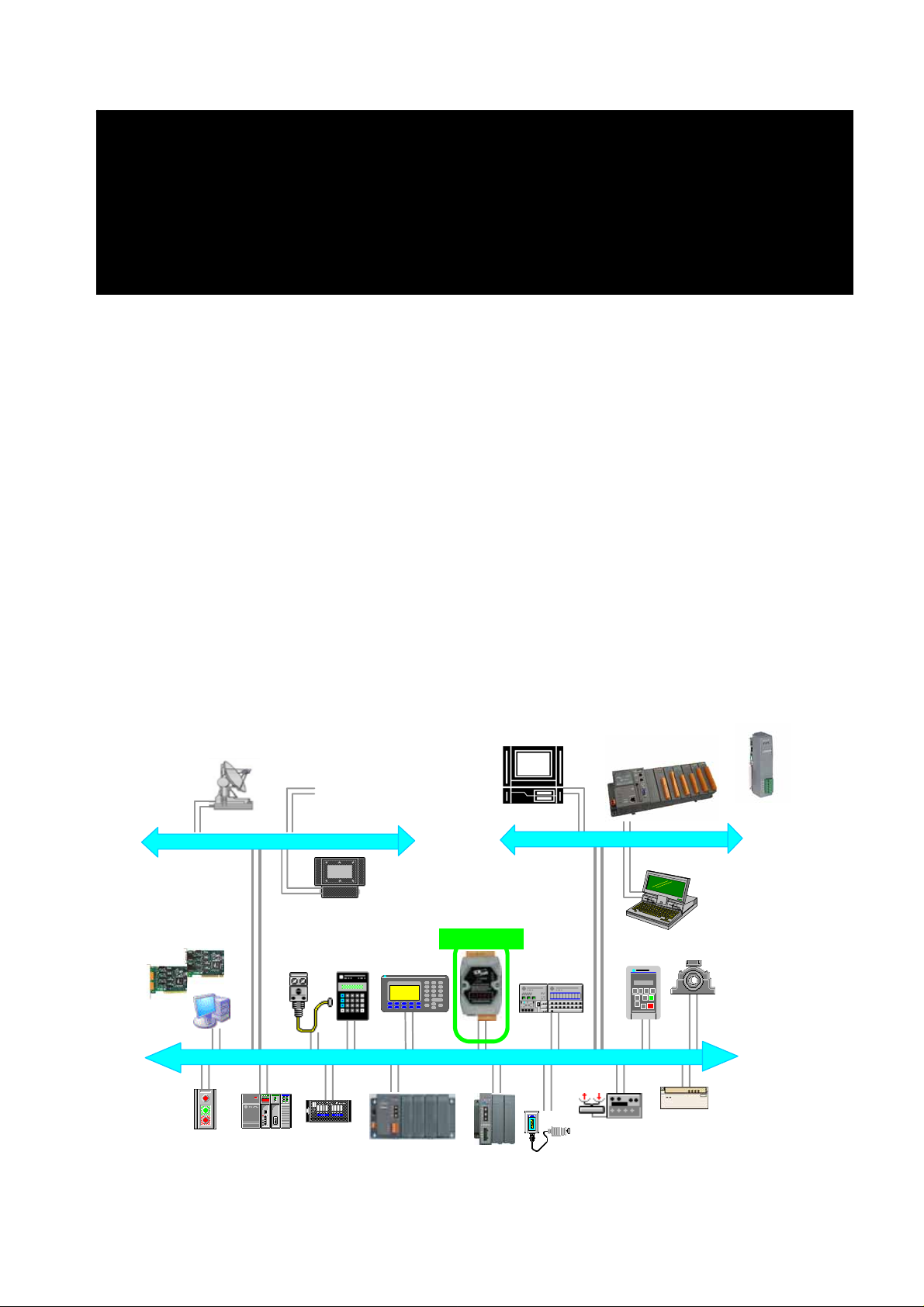
1. Introduction
The CAN (Controller Area Network) is a serial communication protocol, which
efficiently supports distributed real-time control with a very high level of security.
It is an especially suited for networking “intelligent” devices as well as sensors
and actuators within a system or sub-system. In CAN networks, there is no
addressing of subscribers or stations in the conventional sense, but instead,
prioritized messages are transmitted. CANopen is one kind of the network
protocols based on the CAN bus and mainly used for machine control network,
such as textile machinery, printing machines, injection molding machinery, or
packaging machines, etc. CANopen is a low level network that provides
connections between simple industrial devices (sensors, actuators) and
higher-level devices (controllers), as shown in Figure 1.1.
+
I-87123
INFORMATION LAYER
GW-7433D
ALLEN-BRADLEY
F1F6F2F7F3F8F4F9F5
F1F6F2F7F3F8F4F9F5
DEVICE LAYER - CANopen
PanelView 550PanelView 550ALLEN-BRADLEY
7 8 9
7 8 9
4 5 6
4 5 6
1 2 3
1 2 3
. 0 -
. 0 -
<
<
-
<-----------------'
<-----------------'
-
-
^
^
< >
< >
F1
F1
v
v
0
0
CONTROL LAYER
Figure: Example of the CANopen network
GW-7433D MODBUS TCP/CANopen Gateway Quick Start User Guide (Version 1.0, July/2008)
1
Page 2
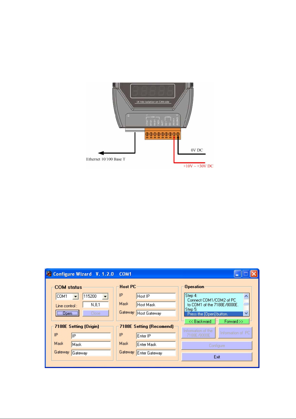
2. Hardware Installation
Step1: Connect the (R) Vs+ and (B) GND pins of the GW-7433D module to
the DC power supply (10~30VDC).
Step3: Connect the Ethernet ports of the GW-7433D and the PC to the hub
with standard network cable respectively.
Step4: Connect the CAN ports of theGW-7433D with CANopen slave devices
3. Configure the GW-7433D
Before starting the GW-7433D gateway, users need to configure the
parameters of it via the “Configuration Wizard” and “GW-7433D Utility” tools.
The details of this procedure are shown below. For more information about
setting steps, please refer to section 5 of the GW-7433D’s user’s manual.
Step1: Configure the network parameters via “Configuration Wizard”
To Use the Configuration Wizard, you must first install PCDiag.
( 8000CD:\Napdos\7188e\TCP\PCDiag\Setup\Setup.exe )
GW-7433D MODBUS TCP/CANopen Gateway Quick Start User Guide (Version 1.0, July/2008)
2
Page 3
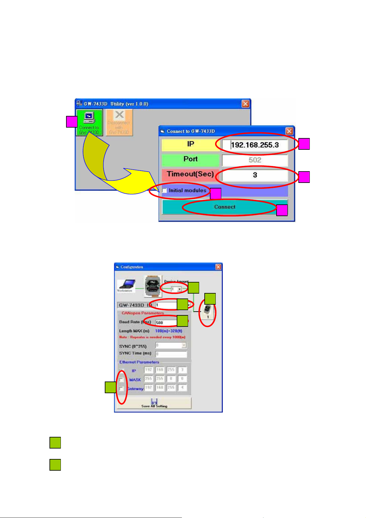
Step2: After configuring the network setting of the GW-7433D, users can use
the GW-7433D Utility tool to configure it.
Step3: Click the “Connect” button to connect with the GW-7433D. These steps
are shown in the following figure.
1
2
3
4
5
Figure : Connection setting of GW-7433D
If the GW-7433D is online and work normally, the GW-7433D Utility tool will
display the “MappingModules” window. Shown in the following figure.
1
5
2
3
4
Connect to the CANopen slave devices with the GW-7433D
1
Æ Select the device amount of CANopen slaves. Maximum amount of CANopen
slaves = 10.
2
Æ The GW-7433D ID number, show in the 7-LED.
GW-7433D MODBUS TCP/CANopen Gateway Quick Start User Guide (Version 1.0, July/2008)
3
Page 4

3
Æ Select the baud rate of CANopne bus.
4
Æ Change the GW-7433D IP, MASK or Gateway.
5
Æ When user finish from step 1 to step 4, please click the button, and the
“CANopenDeviceSetting” window will be pop-up then user can set the
CANopen slave device parameters into the GW-7433D.
Step4: Setting the RxPDO, TxPDO, RxSDO, and TxSDO of “CANopenDeviceSetting”
window. As follow figure.
(1). TxPDO Setting.
1
2
3
8
4 5 6 7
9
Æ It is the code name of this CANopen salve in GW-7433D.
1
Æ Setting the CANopen slave device’s station’s ID.
2
Æ Set the guarding time of the CANopen slave.
3
Æ Key-in the PDO COB-ID (in hex format) of this CANopen slave.
4
Æ Set the RTR mode. In the TxPDO is “1”, and RxPDO is “0”.
5
Æ Select the length of PDO data. Users have to select the correct DLen for
6
each PDO, otherwise some error will happen on the GW-7433D. In this case,
users have to reset the parameters by checking the item “Initialize module”
shown on the figure Connection setting of GW-7433D.
Æ Select the type of data. If DI is selected, this field will present ”P_DIx”. If AI is
7
selected, this field will present “P_Aix”. The letter “P” means PDO. DI or AI
indicate the type of data. The “x” means the number of data.
(Note: The unit of DI is one byte, AI is two bytes).
Æ Delete button. If users want to delete the PDO configuration, click this
8
button.
GW-7433D MODBUS TCP/CANopen Gateway Quick Start User Guide (Version 1.0, July/2008)
4
Page 5

1
2
Æ Please move the mouse to “NO.” column, and select user want to delete
1
row, then click it.
Æ When user finishes the step, then click the “Delete” button.
2 1
(2). RxPDO Setting
User can set the RxPDO parameters by TxPDO’s way, as follow figure.
(note: the Cycle column select always “NO”).
Cycle
(3). Read TxSDO Setting.
Key-in the index (in hex format) and subindex (in hex format) of the object
GW-7433D MODBUS TCP/CANopen Gateway Quick Start User Guide (Version 1.0, July/2008)
5
Page 6

of the CANopen slave, and select the data type to be DI or AI value. Then it
will present “S_DIx” or ”S_AIx”. The letter “S” means SDO. DI or AI indicates
the type of data. The “x” means the number of data.
(Note: The unit of DI is one byte, AI is two bytes)
Bytes subIndex Index
(4). Write RxSDO Setting
User can set the RxSDO parameters by TxSDO’s way, as follow figures.
Æ Exit the “CANopenDeviceSetting” window.
9
Step4: When exit the “CANopenDeviceSetting” window, the “MappingModules”
window Will pop-up again, as follow figure.
GW-7433D MODBUS TCP/CANopen Gateway Quick Start User Guide (Version 1.0, July/2008)
6
Page 7

Then user can click the “Save All Setting” button to write the parameters
into the GW-7433D’s EEPROM, and the GW-7433D will auto-run the firmware
to communication with CANopen slave devices.
After finish the step of above steps, the “ShowMapping” window will be
display. As follow figure.
1
2 3 4
5
CANopen slave device mapping to the Modbus TCP table
Æ
The “DO Mapping “tab is present the DO register mapping of CANopen
1
slave device to the Modbus TCP.
GW-7433D MODBUS TCP/CANopen Gateway Quick Start User Guide (Version 1.0, July/2008)
7
Page 8

Æ The column is Modbus TCP DO address, the row range is 0 ~63.
2
Æ The row is CANopen slave device’s data byte address mapping to Modbus
3
TCP address.
Æ The row is CANopen slave device’s data byte address mapping to Modbus
4
TCP address.
Æ Close the “ShowMapping” window.
5
The “DI Mapping,” ”AI Mapping” and “AO Mapping” of mapping type the
same as the “DO Mapping” of mapping type. In these tabs, the PDO and SDO
arrayal of bytes are form PDO bytes to SDO bytes.
When user over view the “ShowMapping” window finish, Plase close the
“ShowMapping” window, when user close it then the GW-7433D Utility will
display the “MappingModules” window, then user have to close the
“MappingModules” window, the GW-7433D Utility will display the “GW-7433D
Utility ver(1.0.0)” window and click the “Disconnect with GW-7433D” button to
close the window to finish the GW-7433D Utility setting. As follow figure.
Close the GW-7433D Utility setting
GW-7433D MODBUS TCP/CANopen Gateway Quick Start User Guide (Version 1.0, July/2008)
8
 Loading...