

Page 1
www.bb-elec.com orders@bb-elec.com support@bb-elec.com
International Office: 707 Dayton Road PO Box 1040 Ottawa, IL 61350 USA 815-433-5100 Fax 433-5104
European Office: Westlink Commercial Park Oranmore Co. Galway Ireland +353 91 792444 Fax +353 91 792445
PRODUCT INFORMATION B&B ELECTRONICS
FOSTCDRI-Sx
Quick Start Guide
Package Contents
FOSTCDRI-Sx Industrial Serial To Single-mode Fiber
Optic Converter
Datasheet (One per shipment)
Power Terminal Block (installed)
Serial Terminal Block (installed)
Fiber Optic Dust Cover (installed)
If any item is missing or damaged, contact B&B Electronics
for a replacement
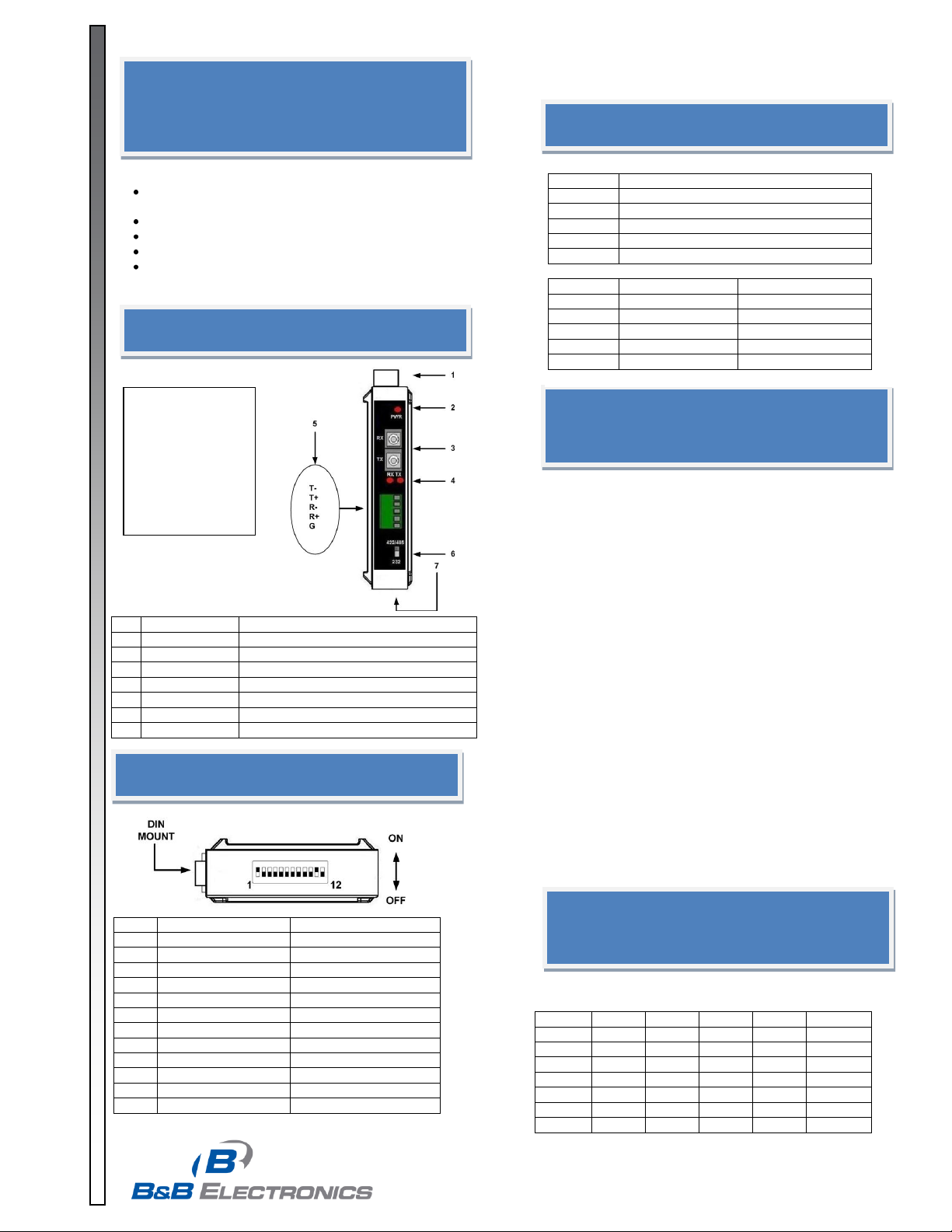
Front Panel
1
Power TB
2 Position, Removable
2
PWR LED
ON When Power Applied
3
Fiber Port
Single-mode, SC or ST Connectors
4
Fiber RX LED
Flashes when data received
4
Fiber TX LED
Flashes when data transmitted
5
Serial Port TB
5 Position, Removable
6
Serial Switch
Selects RS-232 or RS-422/485 Mode
7
DIP Switch
12 Position
Wiring Terminal
Information
1. Copper Wire Only
2. One Conductor Per Terminal
3. Wire Range 28 to 16 AWG
4. Tightening Torque, 1.7 lb-in.
5. Temperature Rating of Field Wiring - 105°C (221° F)
minimum sized for 60° C (140°F) ampacity.
Note: The label
for the serial
connection
terminal block is
not visible with
the TB installed.
This detail is
provided for
reference.
DIP Switch (SW1)
Pos
ON
OFF
1
RS-485
RS-422
2
HALF-DUPLEX
FULL-DUPLEX
3
2-WIRE
4-WIRE
4
2-WIRE
4-WIRE
5
TERMINATION IN
TERMINATION OUT
6
TX BIAS OUT
TX BIAS IN
7
RX BIAS OUT
RX BIAS IN
8
57.6 KBPS
9
38.4 KBPS
10
19.2 KBPS
11
9.6 KBPS
12
MULTI-DROP
POINT-TO-POINT
Terminal Block
Terminal
RS-232
T-
Output
T+
Not Used
R-
Input
R+
Not Used
G
Ground
Terminal
RS 4852-Wire
RS-422/4854-Wire
T-
Data A(-)
TD A(-)
T+
Data B(+)
TD B(+)
R-
Not Used
RD A(-)
R+
Not Used
RD B(+)
G
Ground
Ground
RS-422/485 Baud Rate /
Timeout
SW1
SW1
SW1
SW1
Timeout
Baud 8 9
10
11
(ms)
9600
OFF
OFF
OFF
ON
1.30
19.2K
OFF
OFF
ON
OFF
0.56
38.4K
OFF
ON
OFF
OFF
0.27
57.6K
ON
OFF
OFF
OFF
0.22
76.8K
ON
OFF
ON
ON
0.14
115.2K
ON
OFF
ON
OFF
0.10
p/n 8405 FOSTCDRI-Sx-1112qsg-1/4
© 2009 by B&B Electronics. All rights reserved.
Page 2
p/n 8405 FOSTCDRI-Sx-1112qsg-2/4
www.bb-elec.com orders@bb-elec.com support@bb-elec.com
International Office: 707 Dayton Road PO Box 1040 Ottawa, IL 61350 USA 815-433-5100 Fax 433-5104
European Office: Westlink Commercial Park Oranmore Co. Galway Ireland +353 91 792444 Fax +353 91 792445
PRODUCT INFORMATION B&B ELECTRONICS
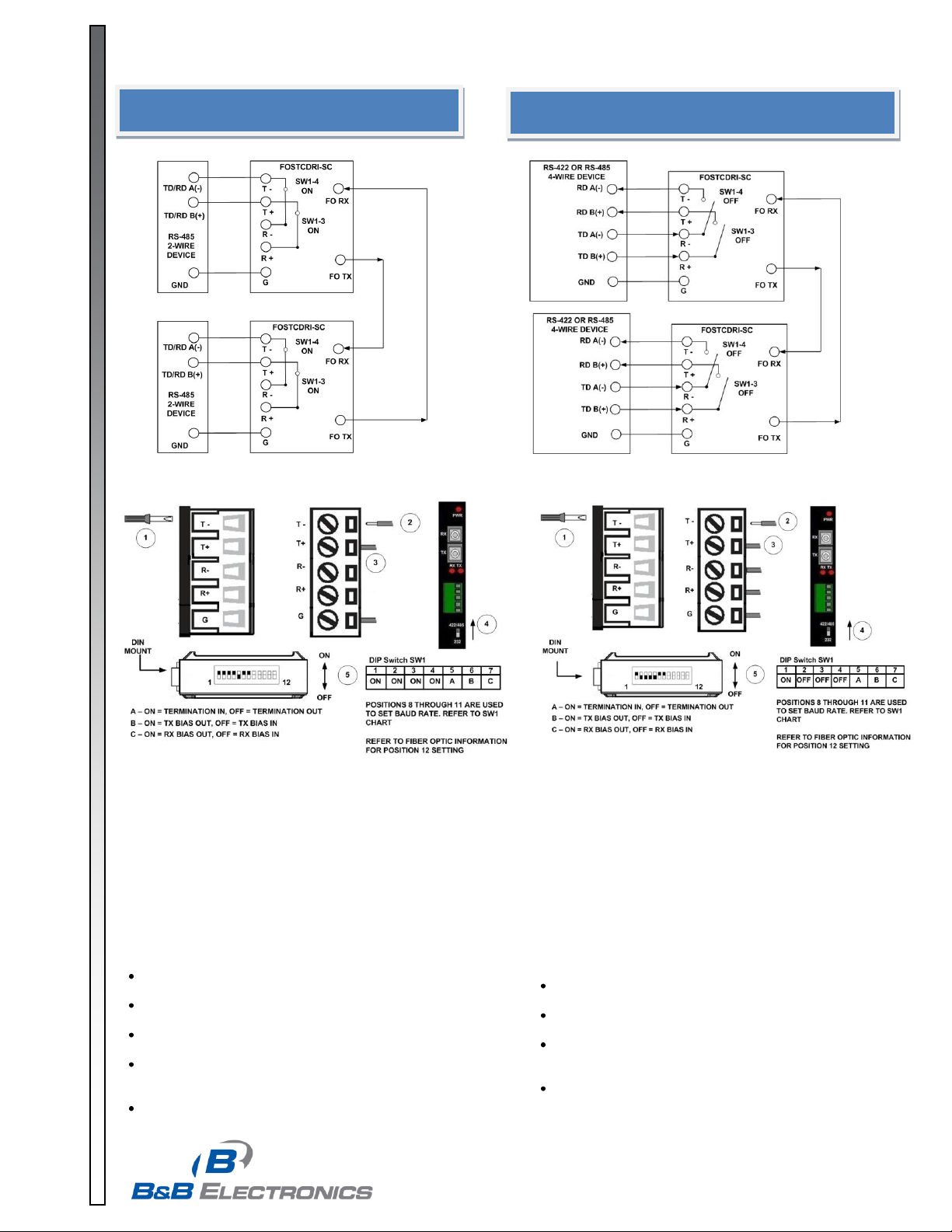
RS-485 2-Wire
1. Loosen the screws to open the Serial TB Lead Clamps for the T-,
T+, and G terminals.
2. Insert the RS-485 2-Wire Signals Leads. The TB will accept 12 to
28 AWG wire.
3. Tighten the screws to close the Serial TB Lead Clamps. Ensure
the clamps hold the leads securely. However, do not over tighten.
4. Position the 422/485/232 Switch to the 422/485 position.
5. Configure the DIP Switch on the bottom of the converter for RS-
485 2-Wire operation.
Installation Notes:
In 2-Wire mode, T(-) and T(+) terminals are tied to the R(-) and
R(+) terminals with DIP Switch SW1-3 and SW1-4.
If Termination is required, a 120Ω resister can be placed
across the R(-) and R(+) terminals by setting SW1-5 to ON.
This converter has 1.2 KΩ pull-up/down bias resistors built
in. To use this bias, set SW1-6 and SW1-7 to ON.
B&B Electronics’ RS-485 Application Note contains more
information about termination and biasing. This reference is
available on our web site.
For a replacement TB, order part number 7466.
RS-422 / RS-485 4-Wire
1. Loosen the screws to open the Serial TB Lead Clamps for the
T-, T+, R-, R+, and G terminals.
2. Insert the RS-422/485 4-Wire Signal Leads. The TB will
accept 12 to 28 AWG wire.
3. Tighten the screws to close the Serial TB Lead Clamps.
Ensure the clamps hold the leads securely. However, do not
over tighten.
4. Position the 422/485/232 Switch to the 422/485 position.
5. Configure the DIP Switch on the bottom of the converter for
RS-422/485 4-Wire operation.
Installation Notes:
If Termination is required, a 120Ω resister can be placed
across the R(-) and R(+) terminals by setting SW1-5 to ON.
This converter has 1.2 KΩ pull-up/down bias resistors
built in. To use this bias, set SW1-6 and SW1-7 to ON.
B&B Electronics’ RS-485 Application Note contains more
information about termination and biasing. This reference
is available on our web site.
For a replacement TB, order part number 7466.
© 2009 by B&B Electronics. All rights reserved.
Page 3

www.bb-elec.com orders@bb-elec.com support@bb-elec.com
International Office: 707 Dayton Road PO Box 1040 Ottawa, IL 61350 USA 815-433-5100 Fax 433-5104
European Office: Westlink Commercial Park Oranmore Co. Galway Ireland +353 91 792444 Fax +353 91 792445
PRODUCT INFORMATION B&B ELECTRONICS
RS-232 Configuration
Fiber Optic
1. Ensure your fiber optic cable is terminated with an
SC type connector. 9/125 micro-meter single-mode
cable is recommended.
2. Connect the converter’s transmitter to the distant end
receiver and vice-versa.
3. DIP Switch SW1-12 is used to select point-to-point or
multi-drop mode. For point-to-point, set the switch to
OFF for both converters. For multi-drop, set the
switch to ON for each converter in the ring. With
SW1-12 in the ON position, receive data will be
looped back to the fiber optic transmitter. Data will
repeat around the ring until it finally reaches its
source. When the data is received by the originator,
timeout circuitry will prevent it from being retransmitted.
Maximum Converters in a Fiber Ring
Baud Rate
RS-232
RS-422/485
19.2 kbps and lower
32
32
37.4 kbps
16
24
115.2 kbps
2
8
1. Loosen the screws to open the Serial TB Lead Clamps for the T-,
R-, and G terminals.
2. Insert the RS-232 Signal Leads into the TB.
3. Tighten the screws to close the Serial TB Lead Clamps. Ensure the
clamps hold the leads securely. However, do not over tighten.
4. Position the 422/485/232 Switch to the 232 position.
Installation Notes:
Set DIP Switch SW1 Positions 1 through 11 (on the bottom of
the converter) to OFF. Set SW1 position 12 to OFF for point-topoint fiber mode.
The wiring example shows a DTE device on one end and a DCE
device on the other.
Handshaking signals are not passed through.
The loopback jumpers shown in the wiring diagram may or
may not be required. Refer to the operating manual for your
RS-232 device for more information.
Fiber Optic Point-to-Point
Fiber Optic Multi-drop Ring
Need More Information?
For more information about serial communications, visit B&B
Electronics’ web site:
www.bb-elec.com
B&B Electronics maintains an extensive technical library available
for download free of charge.
The following titles are of particular interest to users of this product.
RS-422/485 Application Note
RS-232 Connections That Work - DTE/DCE
An Overview of Fiber Optic Technology
p/n 8405 FOSTCDRI-Sx-1112qsg-3/4
© 2009 by B&B Electronics. All rights reserved.
Page 4

p/n 8405 FOSTCDRI-Sx-1112qsg-4/4
www.bb-elec.com orders@bb-elec.com support@bb-elec.com
International Office: 707 Dayton Road PO Box 1040 Ottawa, IL 61350 USA 815-433-5100 Fax 433-5104
European Office: Westlink Commercial Park Oranmore Co. Galway Ireland +353 91 792444 Fax +353 91 792445
PRODUCT INFORMATION B&B ELECTRONICS
RS-232 Loopback Test
1. Configure the converter for RS-232.
2. Set DIP Switch SW1 Position 12 to OFF.
3. Cross-connect the fiber optic transmitter to the fiber optic
receiver using a single-mode patch cord.
4. Connect a PC to the serial port.
5. Using Hyper Terminal or similar program, connect to the
appropriate COM port. Set the baud rate to match the
converter. Ensure Hyper Terminal local echo is OFF.
6. Transmit data. If the same character string is returned,
the test is good.
Attach Power Leads
External Supply Required
1. Power requirement: 10 to 48 VDC, 1.4 W, Class 2.
2. Loosen the screws to open the terminal block lead
clamps.
3. Insert the power lead. TB will accept 12-28 AWG
wire.
4. Tighten the screw to close the terminal block lead
clamp. Ensure the clamp holds the lead securely.
However, do not over tighten.
NOTE: For replacement Terminal Block order Part #
7444.
Mechanical Diagram
© 2009 by B&B Electronics. All rights reserved.
 Loading...