

Page 1
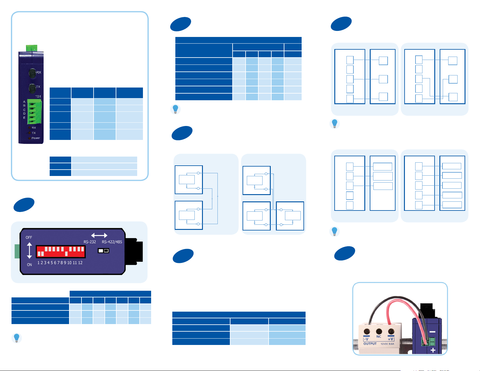
Product Overview
Set DIP Switches for Baud Rate
2
Wire the Converter
5
• Input Voltage 10-48 VDC (56 VDC max)
• Power Consumption 0.5 W (Typical),
1.3W Max
• Duplex multi-mode ber with ST connectors
• Fiber cable specs needed:
62.5/125 micro-meter, 820 nm wavelength
Serial Terminal Block Settings
Terminal
A GND GND GND
B Data B (+) RD B (+) ******
C Data A (-) RD A (-)
D ****** TD B (+) ******
E ****** TD A (-)
RS-485
2-Wire
RS-422/485
4-Wire
LED Indicators
Receive Red, ON when data received on ber
Transmit Red, ON when data sent on ber
Power Red, ON when power applied
Set DIP Switches for RS-232/422/485 Mode
1
RS-232
RS-232 Data
Input
RS-232 Data
Output
Switch Selectable Timeouts
Baud
9.6 K
19.2 K
38.4 K
57.6 K
76.8 K
115.5 K
For baud rates not listed above, refer to:
http://www.bb-elec.com/technical_library.asp
Set DIP Switch 12
3
OFF = Point-to-Point
DIP Switch Position Timeout
8 9 10 11
OFF OFF OFF ON 1.3 ms
OFF OFF ON OFF .56 ms
OFF ON OFF OFF .27 ms
ON OFF OFF OFF .22 ms
ON OFF ON ON .14 ms
ON ON ON OFF .10 ms
ON = Multi-drop Ring
Point-to-Point Multi-drop Ring
FOSTCDRi
Conversion
& Timeout
SW 1-12
OFF
FOSTCDRi
Conversion
& Timeout
SW 1-12
OFF
FO RX
FO TX
FO RX
FO TX
FOSTCDRi
Conversion
& Timeout
SW 1-12
ON
FOSTCDRi
Conversion
& Timeout
SW 1-12
ON
RS-232
Your DeviceFOSTCDRi
A
GND
B
C
TD
D
E
RD
DTE
Computer
Additional tech notes on RS-232 DTE/DCE connections
are located at: http://www.bb-elec.com/technical_library.asp
A
B
C
D
E
Field Device
Your DeviceFOSTCDRi
GND
TD
RD
DCE
RS-422/485
Your DeviceFOSTCDRi
A
FO RX
B
C
FO TX
GND
TD/RD B (+)
TD/RD A (-)
D
FOSTCDRi
FO RX
FO TX
Conversion
& Timeout
SW 1-12
FO TX
FO RX
ON
E
RS-485 2-Wire
Additional tech notes on RS-422/485 connections are located at:
http://www.bb-elec.com/technical_library.asp
A
B
C
D
E
RS-485 4-Wire
Your DeviceFOSTCDRi
GND
RD B (+)
RD A (-)
TD B (+)
TD A (-)
DIP Switch Position
Mode 1 2 3 4 5 6 7
RS-485 2-Wire, Half-duplex ON ON ON ON OFF ON OFF
RS-485 4-Wire, Full-duplex ON OFF OFF
RS-422 Full-duplex OFF OFF OFF OFF OFF ON OFF
If you wish to enable termination, refer to:
http://www.bb-elec.com/technical_library.asp
OFF OFF OFF
OFF
Multi-drop Mode
4
Multi-drop mode allows one serial device to communicate
with up to 31 others around a ber optic ring. Data will repeat
around the ring until it nally reaches its source. When the
data is received by the originator, timeout circuitry will prevent
it from being re-transmitted.
Maximum Converters in a Fiber Ring
Baud Rate RS-232 RS-422/485
19.2 kbps and lower 32 32
38.4 kbps 16 24
115.2 kbps 2 8
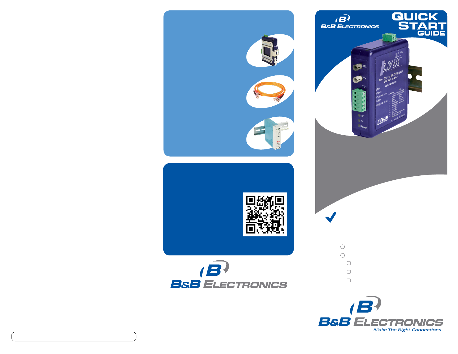
Power the Converter
6
• Input Voltage 10-48 VDC (56 VDC max)
• Power Consumption 0.5 W (Typical), 1.3W Max
Page 2
Troubleshooting
When using Point to Point mode can I set one
of the FOSTCDRi’s as 232 and the other as 422
or 485?
Yes.
What do the TX Bias and RX Bias switches do?
They put biasing in or out of the circuit. There is a 1.2k ohm resistor
across the transmit pair and the receive pair.
(Applies to RS-422/485 only)
BIASING
Please review our biasing tech note on our 422/485
application guide.
CONNECTING A SIGNAL GROUND
(COMMON, REFERENCE) ON THE RS-422/485 SIDE
The specications for most RS-422 and RS-485 devices indicate that
the device can withstand a maximum VCM of -7 volts to +12 volts.
The function of the GND connection is to tie the signal grounds of all
nodes on a network to one common ground potential. This ensures
that the common mode voltage cannot exceed the specied value.
A signal ground is required on the FOSTCDRi because it is an
optically isolated device. If you do not have a signal ground
(common, reference) on your RS -422/485 device you can connect
to the DC power ground of your RS-422/485 device.
Caution: Be sure that this is connected correctly.
Recommended Accessories
and Power Supplies
35mm DIN Rail to Panel
Mount Bracket
http://www.bb-elec.com/FOSTCDRi/
ACC
Fiber Optic Cable
http://www.bb-elec.com/FOSTCDRi/
ACC
Industrial Power Supply
http://www.bb-elec.com/FOSTCDRi/
ACC
Fast, Easy Answers
• First, check step 6.
DRPM25
DFMM-STST-1M
MDR-20 -24
FOSTCDRi & FOSTCDRi-INV
Industrial Serial to Multi-mode Fiber Converters
The FOSTCDRi has the ber optic transmit light ON in the idle state.
If you require the ber optic transmit light OFF in the idle state you
can order the FOSTCDRi-INV. (The FOSTCDRi and the FOSTCDRi-INV
will not work together.)
What is the difference between the FOSTCDRi
and the FOSTCDRi-INV?
On the FOSTCDRi we keep the light in the ber turned on when no
data is transmitted and the input signal is in the MARK state (idle).
If light is lost or too low, the electrical signals go to the SPACE state.
The input signal turns the light Off/On in step with the data. This
model has no indicator for Transmit or Receive, if no light is received,
the RD output will be positive relative to GND (normally negative),
and in RS-422 or RS-485 mode, no light will set the TD(A)- line
high relative to TD(B)+. The usual voltage with light in the ber and
no signal sets the B line high relative to A (about 4.4 Volts DC no
termination). To check, connect a ber patch cable from the TX
connector into the RX connector.
The FOSTCDRi- INV is the opposite. The ber is off in the idle state.
Document number – pn8953_r002_FOSTCDRi-x_1312qsg
• Then use your smart
phone to access complete
documentation on our
web site. Simply scan
the code to the right.
http://www.bb-elec.com/FOSTCDRi
1-888-948-2248 | Europe: +353 91 792444
www.bb-elec.com
707 Dayton Road | PO Box 1040 | Ottawa, IL 61350
Phone: 815-433-5100 | Fax: 815-433-5109
www.bb-elec.com | E-mail: info@bb-elec.com
© 2012 B&B Elect ronics Manufacturin g Company
First Things First...
Before you begin, be sure you have
the following:
FOSTCDRi Fiber Converter
Additional items required but not included:
10 - 48 VDC Power Supply
Serial Cable
Muli-mode Fiber Optic Cable with
ST Connectors (62.5/125 micro-meter)
Fast and easy on the web:
www.bb-elec.com
Page 3

RS-232 Loopback Test
7
1. Congure the converter
for RS-232.
2. Set DIP switch 12 to OFF.
3. Cross-connect the ber
optic transmitter to the ber
optic receiver.
4. Connect a PC to the serial port.
5. Using HyperTerminal or
a similar program, connect
to the appropriate COM port.
Make sure that hyper
terminal local echo is OFF.
6. Transmit data. If the same
character set is returned,
the test is good.
GND
TD
RD
DTR
DSR
RTS
CTS
RS-232 Loopback Test
FOSTCDRiRS-232 DTE
A
FO RX
C
FO TX
E
FOSTCDRi & FOSTCDRi-INV
Industrial Serial to Multi-mode Fiber Converters
Information—UL Class 1 Div 2
1. Power, input /output (I/O) wiring must be in accordance
with Class 1 Division 2 wiring methods [Article 501.10(B)
of the National Electric code, NFPA70] and in accordance
with the local authority having jurisdiction.
2. Maximum ambient air temperature 80° C.
3. WARNING – EXPLOSION HAZARD: SUBSTITUTION OF
ANY COMPONENTS MAY IMPAIR SUITABLITY FOR CLASS 1,
DIVISION 2.
4. WARNING – EXPLOSION HAZARD: WHEN IN HAZARDOUS
LOCATIONS, TURN OFF POWER BEFORE REPLACING
OR WIRING MODULES
5. WARNING – EXPLOSION HAZARD: DO NOT DISCONNECT
EQUIPMENT UNLESS POWER HAS BEEN SWITCHED OFF
OR THE AREA IS KNOWN TO BE NON -HAZARDOUS.
6. WARNING – THIS APPARATUS IS SUITABLE FOR USE IN
CLASS 1 DIVISION 2, GROUPS A, B, C, AND D,
OR UNCLASSIFIED AREAS.
 Loading...