

Page 1
© 2002 by B&B Electronics. All rights reserved.
www.bb-elec.com orders@bb-elec.com support@bb-elec.com
International Office: 707 Dayton Road PO Box 1040 Ottawa, IL 61350 USA 815-433-5100 Fax 433-5104
European Office: Westlink Commercial Park Oranmore Co. Galway Ireland +353 91 792444 Fax +353 91 792445
PRODUCT INFORMATION B&B ELECTRONICS
TX
RX
FOSTC
RX
TX
FOSTC
RS-232
RS-422
or RS-485
Device
Duplex
Multimode
Fiber
or System
RS-232
RS-422
or RS-485
Device
or System
SW1:6 = OFF SW1:6 = OFF
Point to Point
TX
RX
FOSTC
RX
TX
FOSTC
RS-232
RS-422
or RS-485
Device
Multimode
Fiber
or System
RS-232
RS-422
or RS-485
Device
or System
RX
TX
FOSTC
RS-232
RS-422
or RS-485
Device
or System
RX
TX
FOSTC
RS-232
RS-422
or RS-485
Device
or System
SW1:6 = ON
SW1:6 = ON
SW1:6 = ON
SW1:6 = ON
Multi-Drop Ring
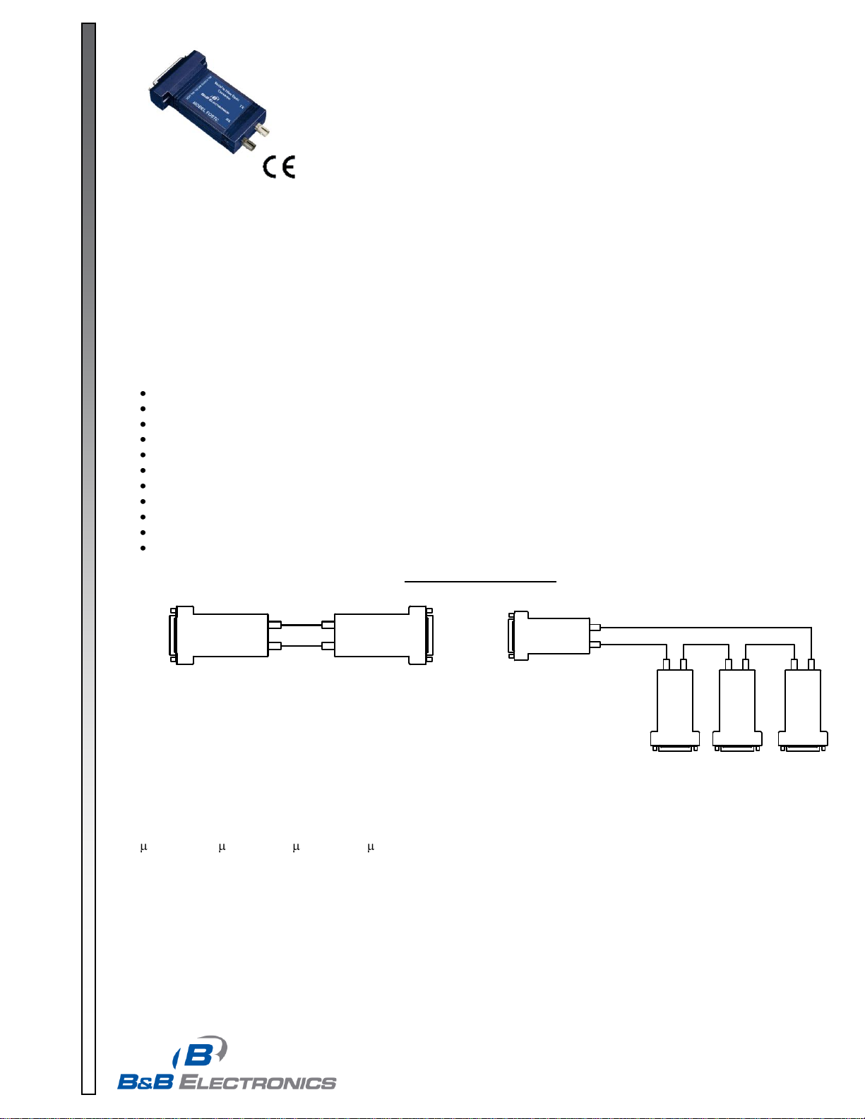
FOSTC-0812-1/6
Model FOSTC
RS-232, 422 or 485 Signals Up To
2.5 Miles with Fiber Optic Modem
Description
Fiber optic cabling has inherent resistance to EMI/RFI and transient immunity, making it ideal for industrial and utility
data communication applications.
The FOSTC was designed to provide the most versatile connection possible between any asynchronous serial
equipment using Fiber Optic cable. The FOSTC can be used for point-to-point communications between serial devices,
or in a multi-drop fiber ring configuration, allowing multiple serial devices to communicate with each other.
It allows any two pieces of asynchronous serial equipment to communicate full or half-duplex over two fibers at typical
distances up to 2.5 miles (4 km). To extend the distance of the fiber link beyond 2.5 miles, use B&B model FOSTDRP
Fiber Optic Repeater.
Features/Applications
Point-to-point or multi-drop ring configuration
RS-232, RS-422, or RS-485 operation
Use as a converter from RS-232 to RS-422/485
RS-422/485 data rates up to 500 kbps
RS-485 Automatic Send Data driver control
Inherent EMI/RFI and transient immunity.
Eliminate ground loops
Extend serial signals up to 2.5 miles
Uses popular ST type fiber connectors
Standard DB25 female (DCE) for serial connections
12VDC powered (separate supply required)
Figure 1: Typical Setups
Fiber Optic Connections
The FOSTC uses a separate LED emitter and photo-detector operating at 820 nm wavelength. Connections to the
emitter and detector are on ST type connectors. Almost any multimode glass fiber size can be used including 50/125
m, 62.5/125 m, 100/140 m, and 200 m. One fiber is required for each connection between a transmitter and
receiver. In a point-to-point configuration, two fibers are required between the two modems, one for data in each
direction. A multi-drop ring configuration requires one fiber between TX and RX around the loop. See Figure 1 for
typical point-to-point and multi-drop configurations.
The most important consideration in planning the fiber optic link is the “power budget” of the fiber modem. This value
represents the amount of loss in dB that can be present in the link between the two modems before the units fail to
perform properly. This value includes line attenuation as well as connector loss. For the FOSTC the typical connector-
Page 2
© 2002 by B&B Electronics. All rights reserved.
www.bb-elec.com orders@bb-elec.com support@bb-elec.com
International Office: 707 Dayton Road PO Box 1040 Ottawa, IL 61350 USA 815-433-5100 Fax 433-5104
European Office: Westlink Commercial Park Oranmore Co. Galway Ireland +353 91 792444 Fax +353 91 792445
PRODUCT INFORMATION B&B ELECTRONICS
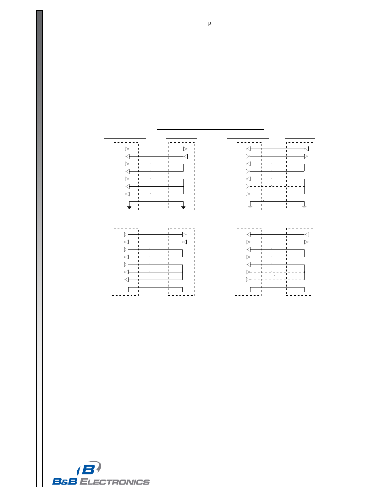
Figure 2: RS-232 Connection Diagrams
DB9 DTE Device
TD
RD
RTS
CTS
DTR
DSR
DCD
Signal GND
3
2
7
8
4
6
1
5
DB9 DCE Device
TD
RD
RTS
CTS
DTR
DSR
DCD
Signal GND
3
2
7
8
4
6
1
5
DB25 DTE Device FOSTC DB25
TD
RD
RTS
CTS
DTR
DSR
DCD
Signal GND
2
3
4
5
20
6
8
7
2
3
4
5
20
6
8
7
or
DB25 DCE Device
TD
RD
RTS
CTS
DTR
DSR
DCD
Signal GND
3 (RD)
2 (TD)
4
5
20
6
8
7
or
FOSTC DB25
FOSTC DB25 FOSTC DB25
2
3
4
5
6
8
7
2
3
4
5
20
6
8
7
3 (RD)
2 (TD)
4
5
20
6
8
7
FOSTC-0812-2/6
to-connector power budget is 12.1 dB. Because 62.5/125 m cable typically has a line attenuation of 3 dB per Km at
820 nm, the 12.1 dB power budget translates into 2.5 miles. This assumes no extra connectors or splices in the link.
Each extra connection would typically add 0.5 dB of loss, reducing the possible distance by 166 m (547 ft.). The actual
loss should be measured before assuming distances.
RS-232 Connections
Connection of the FOSTC is simple and straightforward. The DB25 female serial connector is used for connecting to
either RS-232, RS-422 or RS-485. The RS-232 signals are pinned as a DCE device (input on Pin 2 and output on Pin
3). A straight through cable can be used from your DB25 port on any DTE device such as a PC or terminal. A standard
9 to 25-pin adapter can be used in cases where the serial port on the DTE device is a DB9. A null modem cable or
adapter that swaps pins 2 and 3 is needed for connecting to modems or other DCE devices. See Figure 2 for
connection diagrams to 9 pin and 25 pin DTE and DCE devices. Because RS-422 and RS-485 signals are also
available on the same connector, take special care not to hook any external signals to these pins. This is not a problem
for most serial devices, but a custom cable must be made that does not connect to the extra pins on the DB25
connector if your device has power or special non-standard outputs.
RS-422 & RS-485 Connections
The RS-422/485 driver and receiver are connected to 4 pins on the DB25 connector. Signal ground is on Pin 7. When
connecting to a four-wire RS-422/485 device or system, connect the output of your device to pins 16 (B or +) and 17 (A
or +). Connect the input to your device to pins 14 (B or +) and 15 (A or -). For two-wire RS-485 systems, the driver and
receiver of the FOSTC must be connected together by tying pins 14 and 16 together and 15 and 17 together. This
allows the FOSTC to communicate half-duplex over the same pair. Refer to Figure 3 for connection diagrams to your
RS-422 or RS-485 equipment.
If termination is needed, a spot on the PCBD of the FOSTC labeled Rt allows you to solder in a termination resistor
across the RD(A) and RD(B) lines. Removing R8 and R16 and replacing them with through-hole components can also
change the off-state bias resistor values. Before making modifications to the FOSTC, be sure to consult B&B
Electronics’ free RS-422/485 Application Note or other sources of information to see if termination is necessary. The
Application Note is available from our Web site, or call and we will be happy to send you one at no charge.
Page 3

© 2002 by B&B Electronics. All rights reserved.
www.bb-elec.com orders@bb-elec.com support@bb-elec.com
International Office: 707 Dayton Road PO Box 1040 Ottawa, IL 61350 USA 815-433-5100 Fax 433-5104
European Office: Westlink Commercial Park Oranmore Co. Galway Ireland +353 91 792444 Fax +353 91 792445
PRODUCT INFORMATION B&B ELECTRONICS
Table 1: RS-485 Timeout Selection
Baud Rate
Pos. 1
Pos. 2
Pos. 3
Pos. 4
Pos. 5
R9
Time(ms)
1200
ON
OFF
OFF
OFF
OFF
820 K
8.20
2400
ON
OFF
OFF
OFF
OFF
430 K
4.30
4800
OFF
OFF
OFF
OFF
ON
Not Used
2.20
9600
OFF
OFF
OFF
ON
OFF
Not Used
1.30
19.2K
OFF
OFF
ON
OFF
OFF
Not Used
0.56
38.4K
OFF
ON
OFF
OFF
OFF
Not Used
0.27
57.6K
ON
OFF
OFF
OFF
OFF
Not Used
0.22
76.8K
ON
OFF
ON
ON
OFF
Not Used
0.14
115.2K
ON
ON
ON
OFF
OFF
Not Used
0.10
153.6K
ON
OFF
OFF
OFF
OFF
6.2 K
0.06
230.4K
ON
OFF
OFF
OFF
OFF
4.3 K
0.04
460.8K
ON
OFF
OFF
OFF
OFF
2.2 K
0.02
Table 2: 422/485 Switch Settings
Position 7
TX Enable
Position 8
RX Enable
RS-485
2-Wire Mode
(half duplex)
ON
ON
RS-485
4-Wire Mode
(full duplex)
ON
OFF
RS-422 Mode
(full duplex)
OFF
OFF
Figure 3: RS-422/485 Connection Diagrams
422/485 4W Device
TD A (-)
TD B (+) 16 RD B
17 RD A
14 TD B
15 TD A
RD A (-)
RD B (+)
7GND
FOSTC DB25
485 2 Wire Device
Data A (-)
16 RD B
17 RD A
14 TD B
15 TD A
Data B (+)
7GND
FOSTC DB25
FOSTC-0812-3/6
Dip-Switch Setup
The Dip-Switch (SW1) on the FOSTC
defines the mode of operation when being used
for RS-422 or RS-485. Positions 1 through 5 on
the switch determine the timeout of the RS-485
driver. Because the driver is controlled by
hardware, a specific time must be set to tell the
hardware how long to wait for data on the fiber
side before turning off the RS-422/485 driver. If
this time is set too short, the driver could be
disabled before transmission is complete,
resulting in data corruption. If the time is set too
long, the RS-485 device may respond before
the RS-422/485 driver in the FOSTC is
disabled, corrupting this response. We
recommend that the timeout be set for
approximately one character time or longer.
The character times for several different baud
rates are selectable on switch positions 1
through 5. If you need a different timeout than what is provided, R10 can be removed and replaced with a different
value R9. Table 1 shows different timeout values for the switch positions as well as typical R9 replacement values.
Position 6 of SW1 sets the unit in a “Multidrop” mode or a “Point-to-Point” mode. When the FOSTC is set in a
“Multidrop” mode, data arriving on the Fiber Optic receiver is repeated back out the transmitter. When set in a “Pointto-Point” mode, data arriving at the Fiber optic receiver is not sent back out the Fiber Optic transmitter. Position 6 must
be turned “On” when the FOSTC is to be used in a multi-drop ring configuration. It must be turned “Off” when the
FOSTC is to be used as either end of a point-to-point communication line. See Figure 3 for typical system setups using
the FOSTC in its different modes.
Positions 7 and 8 of SW1 determine when the RS-422/485 driver
and receiver are enabled. Position 7 controls the driver and Position
8 controls the receiver. For RS-422 operation, set both switches to
the “Off” position. For multi-drop RS-485 four-wire systems, position
7 should be “On” and position 8 should be “Off.” This allows the
receiver to be enabled all of the time and eliminates some possible
timing problems. For RS-485 two-wire systems, both switches
should be in the “On” position. This disables the RS-422/485
receiver whenever the driver is enabled, preventing data from being
echoed back to the fiber side of the FOSTC.
Table 2 illustrates the switch settings for typical setups.
Page 4

© 2002 by B&B Electronics. All rights reserved.
www.bb-elec.com orders@bb-elec.com support@bb-elec.com
International Office: 707 Dayton Road PO Box 1040 Ottawa, IL 61350 USA 815-433-5100 Fax 433-5104
European Office: Westlink Commercial Park Oranmore Co. Galway Ireland +353 91 792444 Fax +353 91 792445
PRODUCT INFORMATION B&B ELECTRONICS
RS-485 NETWORK
FOSTC
FOSTDRP
RX
TX
TX
RX
TX
RX
RS-485 NETWORK
FOSTCDR
RS-485 NETWORK
FOSTC
TX
RX
FOSTC
TX
RX
FOSTDRP
RX
TX
TX
RX
BUILDING A BUILDING B
BUILDING C
UP TO 2.5 MILES UP TO 2.5 MILES
UP TO 2.5 MILES UP TO 2.5 MILES
CENTRAL PATCH BUILDING
+12 VDC
+10 to 30 VDC
+12 VDC +12 VDC
+10 to 30 VDC
RX TX
+10 to 30 VDC
FOSTC-0812-4/6
Multi-Drop Operation
A multi-drop configuration is created by forming a ring of FOSTCs (see Figure 1). Whichever serial device sends data,
all other devices receive it. The data is repeated around the fiber ring until it reaches the source, where it is blocked.
There is no echo back to the serial side of the sending device. Each fiber transmitter must be connected to the
following converter’s receiver. Set SW1:6 to the “On” position on all FOSTCs in the ring. Any device can be full-duplex
(RS-232, RS-422, or four-wire RS-485), or half duplex RS-485. Because all data shares the same path on the ring,
only one device can send data at a time.
Interfacing to Fiber Devices from Other Manufacturers
Note: The factory default for the LED emitter is to have the light ON in the idle state. To interconnect with other devices
that have the light OFF in the idle state, this unit would need to be modified. To modify the unit so that the light is OFF
in the idle state, contact B&B Electronics Technical Support.
Typical Installation Configuration
Below is a University Campus setup that illustrates the basic configuration of a typical Fiber Optic Network. This
scenario uses a combination of B&B Fiber devices including 3 of the FOSTCs, 2 of the fiber repeaters FOSTDRP, and
one of the DIN Rail mount Fiber Converters FOSTCDR. Each of the items requires a power supply (not shown).
Figure 4. Typical Campus Setup
Page 5

© 2002 by B&B Electronics. All rights reserved.
www.bb-elec.com orders@bb-elec.com support@bb-elec.com
International Office: 707 Dayton Road PO Box 1040 Ottawa, IL 61350 USA 815-433-5100 Fax 433-5104
European Office: Westlink Commercial Park Oranmore Co. Galway Ireland +353 91 792444 Fax +353 91 792445
PRODUCT INFORMATION B&B ELECTRONICS
Recommended Maximum FOSTCs
in a Fiber Ring Topology.
Baud Rate
RS-232
Operation
RS-422/485
Operation
460.8 kbps
N/A
2
230.4 kbps
N/A
4
115.2 kbps
2 8 57.6 kbps
8
16
38.4 kbps
16
24
19.2 kbps
and lower
32
32
Parameter
Min.
Typical
Max.
Conditions
Data Rates
(RS-232 Operation)
0 bps
115.2 kbps
Data Rates
(RS-422/485 Operation)
0 bps
500 kbps
Power Supply Voltage
10 VDC
12 VDC
14 VDC
Power Supply Current Draw
140 mA
Full RS-485 Termination
Optic Wavelength
820 nm
Fiber TX Launch Power
-17 dBm
-13 dBm
-10 dBm
Minimum Required Fiber Rx Power
-25.4 dBm
-24 dBm
Maximum Receiver Power
-10 dBm
Coupled Power Budget
12.1 dB
Fiber Range
2.5 Miles
End to End Delay
2000 ns
2650 ns
Point to Point RS-232 Operation
(See Notes 1 & 2)
End to End Delay
550 ns
1000 ns
Point to Point RS-422/485 Operation
(See Notes 1 & 2)
End to End Skew
900 ns
1100 ns
Point to Point RS-232 Operation
(See Note 3)
End to End Skew
50 ns
120 ns
Point to Point RS-422/485 Operation
(See Note 3)
Maximum Total Fiber Ring Length
5 Miles
(See Note 1)
Delay between Rx & Tx on a fiber ring
52 µs
(See Note 4)
FOSTC-0812-5/6
Specifications/Features
Transmission Line: Dual multimode optical cable
Point-to-Point Transmission: Asynchronous, half or full-duplex
Multi-Drop Transmission: Asynchronous, half duplex fiber ring
Interfaces: RS-232, RS-422, or RS-485
Connectors: DB25 female for serial connection, ST connectors for fiber
Dimensions: 4.3 x 2.3 x 0.95 in (11 x 5.9 x 2.5 cm)
Power Supply Connections: 2.5mm phone jack (Tip Positive) or DB25 pins 25(+) & 12(-)
Recommended Power Supply: B&B Model# 232PS3
All specifications given using 62.5/125µm glass multi-mode fiber.
Note 1: For the total transmission time over long fibers, the time to
transverse the fiber must be considered if delay is an issue. Light takes
about 8.05 microseconds to travel over 1 mile of fiber.
Note 2: When operating in a ring configuration, each node in addition to
the two in the point-to-point specification adds an additional 100 to 200
nanoseconds of delay.
Note 3: When operating in a ring configuration, each node in addition to
the two in the point-to-point specification adds an additional 50 to 70
nanoseconds of skew.
Note 4: When operating in a ring configuration, each serial device must
wait at least this minimum time between receiving data from the ring and
transmitting back on to it.
Page 6

© 2002 by B&B Electronics. All rights reserved.
www.bb-elec.com orders@bb-elec.com support@bb-elec.com
International Office: 707 Dayton Road PO Box 1040 Ottawa, IL 61350 USA 815-433-5100 Fax 433-5104
European Office: Westlink Commercial Park Oranmore Co. Galway Ireland +353 91 792444 Fax +353 91 792445
PRODUCT INFORMATION B&B ELECTRONICS
DECLARATION OF CONFORMITY
Manufacturer’s Name: B&B Electronics Manufacturing Company
Manufacturer’s Address: P.O. Box 1040
707 Dayton Road
Ottawa, IL 61350 USA
Model Number: FOSTC
Description: High-Speed Fiber Optic Modem
Type: Light industrial ITE equipment
Application of Council Directive: 89/336/EEC
Standards: EN 55022
EN 61000-6-1
EN 61000 (-4-2, -4-3, -4-4, -4-5, -4-6, -4-8, -4-11)
Robert M. Paratore, Director of Engineering
FOSTC-0812-6/6
Figure 5: FOSTC Circuit Diagram
 Loading...