

Page 1
Quick Start Guide
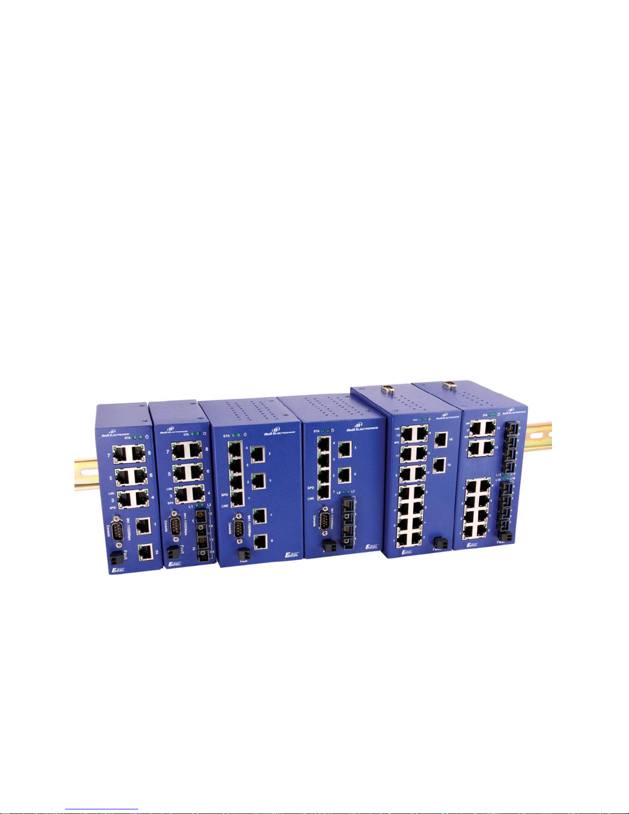
Elinx ESW500 Series
Managed Din Rail Ethernet Switch
Page 2

Installation Guide Documentation Number: ESW500series-1012qsg
B&B Electronics Mfg Co Inc – 707 Dayton Rd - PO Box 1040 - Ottawa IL 61350 - Ph 815-433-5100 - Fax 815-433-5104 – www.bb-elec.com
B&B Electronics – Westlink Commercial Park – Oranmore, Galway, Ireland – Ph +353 91-792444 – Fax +353 91-792445 – www.bb-europe.com
ESW500 Series
Documentation Number: ESW500series-1012qsg
International Headquarters:
707 Dayton Road
Ottawa, IL 61350 USA
Phone (815) 433-5100
Website: www.bb-elec.com
Sales e-mail: orders@bb-elec.com
Technical Support: support@bb.elec.com –
European Headquarters
B&B Electronics
Westlink Commercial Park
Oranmore, Co. Galway, Ireland
Phone +353 91-792444
Website: www.bb-europe.com
Sales e-mail: sales@bb-europe.com
Technical Support: support@bb-europe.com
Original – April 2011
©2011 No part of this publication may be reproduced or transmitted in any form or by any means,
electronic or mechanical, including photography, recording, or any information storage and retrieval
system without written consent. Information in this manual is subject to change without notice, and does
not represent a commitment on the part.
B&B Electronics Manufacturing shall not be liable for incidental or consequential damages resulting from
the furnishing, performance, or use of this manual. All brand names used in this manual are the
registered trademarks of their respective owners. The use of trademarks or other designations in this
Page 3

publication is for reference purposes only and does not constitute an endorsement by the trademark
holder.
Page 4

Page 5

Installation Guide Documentation Number: ESW500series-1012qsg i
B&B Electronics Mfg Co Inc – 707 Dayton Rd - PO Box 1040 - Ottawa IL 61350 - Ph 815-433-5100 - Fax 815-433-5104 – www.bb-elec.com
B&B Electronics – Westlink Commercial Park – Oranmore, Galway, Ireland – Ph +353 91-792444 – Fax +353 91-792445 – www.bb-europe.com
Table of Contents
OVERVIEW .................................................................... 1
Features ....................................................................................................... 2
Package Check List .................................................................................... 2
Front Panel – ESW508 Series .................................................................... 3
Front Panel - ESWG510 Series ................................ ................................ . 4
Front Panel – ESW516 Series .................................................................... 5
LED Description ......................................................................................... 6
Mounting Options ...................................................................................... 7
INITIAL SETUP .............................................................. 7
Getting Started .......................................................................................... 7
Changing the IP address of the Computer ................................................ 7
Console Mode.............................................................................................. 8
Ports ........................................................................................................... 10
RJ45 ........................................................................................................ 10
Gigabit Copper/SFP (mini-GBIC) COMBO ports ................................. 12
SFP Installation and Connection ............................................................ 13
Cabling ...................................................................................................... 14
100Base FX SC Fiber ............................................................................. 15
Fiber connection illustration ................................................................... 15
DC / AC Power Connections ................................................................... 16
Fault Relay ................................................................................................ 16
Default Settings ......................................................................................... 16
Page 6

Installation Guide Documentation Number: ESW500series-1012qsg
B&B Electronics Mfg Co Inc – 707 Dayton Rd - PO Box 1040 - Ottawa IL 61350 - Ph 815-433-5100 - Fax 815-433-5104 – www.bb-elec.com
B&B Electronics – Westlink Commercial Park – Oranmore, Galway, Ireland – Ph +353 91-792444 – Fax +353 91-792445 – www.bb-europe.com
Console Port (DB9 Male) ....................................................................... 16
Serial Cable Pin out ................................................................................ 16
Network Settings .................................................................................... 17
Default Security ...................................................................................... 17
Page 7

Installation Guide Documentation Number: ESW500series-1012qsg 1
B&B Electronics Mfg Co Inc – 707 Dayton Rd - PO Box 1040 - Ottawa IL 61350 - Ph 815-433-5100 - Fax 815-433-5104 – www.bb-elec.com
B&B Electronics – Westlink Commercial Park – Oranmore, Galway, Ireland – Ph +353 91-792444 – Fax +353 91-792445 – www.bb-europe.com
Overview
B&B Electronics Elinx family of Managed Industrial Din Rail mount
Ethernet switches have been designed to meet light Industrial and
commercial communication requirements.
The ESW500 Managed Series offers a variety of Industrial models. The
switch configurations range from 8 ports to 16 ports with all RJ45 copper to
RJ45 copper with multi mode, single mode, and or SFP gigabit ports.
Two ports can be used for network redundancy by implementing our
RingOn technology. RingOn has been developed to provide a rapid
recovery system for Industrial networks. If any part of the ring disconnects
the network communications will automatically be restored by RingOn
technology.
All RJ45 copper ports support auto-negotiation, 10/100Mbps data rate,
full/half duplex, flow control and auto MDI/MDIX. The Elinx switches
provide advanced management functions such as: RingOnTM, VLAN,
Trunking, QoS (Quality of Service), IGMP Snooping, Port Rate Control,
Port Mirroring, Static Mac Address Forwarding Table, SNMP (Simple
Network Management Protocol), Diagnosis, Email/Relay fault warning and
field Firmware Update.
The ESW500 Series will support IEEE 802.3 (10Base-T), IEEE 802.3u
(100BaseTX) and (100BaseFX), 802.3ab 1000Base(X), IEEE 802.3z for
1000BaseSX/LX/LHX/ZX, 802.3x for flow control, full and half duplex,
MDI/MDIX auto-sensing.
The operating temperature range for standard models are -10˚C to 60˚C
with wide temperature models supporting -40˚C to 75˚C. The ambient
relative humidity rating is 5 to 95% (Non-condensing).
Page 8

2 Installation Guide Documentation Number: ESW500series-1012qsg
B&B Electronics Mfg Co Inc – 707 Dayton Rd - PO Box 1040 - Ottawa IL 61350 - Ph 815-433-5100 - Fax 815-433-5104 – www.bb-elec.com
B&B Electronics – Westlink Commercial Park – Oranmore, Galway, Ireland – Ph +353 91-792444 – Fax +353 91-792445 – www.bb-europe.com
Features
Light Industrial and Commercial 61000-6-1 specifications
-10 to 60°C or -40 to 75°C (-T models) temperature rating
Supports IEEE 802.3 10Base-T,802.3u 100Base-TX
IEEE 802.3z for 1000BaseSX/LX/LHX/ZX
RJ-45 port supports auto MDI/MDI-X function
SC Single mode and Multi mode fiber connectors
Gigabit options with copper and SFP combo ports
Web Browser Management and Configuration
RingOn redundant rapid recovery system
Rapid Spanning Tree Protocol recover system
IGMP with Query mode for multimedia application
Port based VLAN / 802.1 Q Tag VLAN
Relay alarm output for system events
Port mirroring for diagnostics
256K bytes packet buffer
8k MAC address table
12 to 36 VDC power input (All Models)
10 to 24 VAC (ESW508, ESW516 Models)
Din Rail and Panel Mount
100% burn in testing
5 year warranty
Package Check List
B&B Managed Switch
Din rail and panel mounting
Serial cable for console port
Installation Guide
CD-with User’s Manual
Page 9

Installation Guide Documentation Number: ESW500series-1012qsg 3
B&B Electronics Mfg Co Inc – 707 Dayton Rd - PO Box 1040 - Ottawa IL 61350 - Ph 815-433-5100 - Fax 815-433-5104 – www.bb-elec.com
B&B Electronics – Westlink Commercial Park – Oranmore, Galway, Ireland – Ph +353 91-792444 – Fax +353 91-792445 – www.bb-europe.com
Front Panel – ESW508 Series
Bottom View
1. System Ready
2. Redundant Power LED
3. 10/100BaseT(X) RJ45 Ports
4. Link LED
5. Speed LED
6. 100BaseFX, SC Fiber Port
7. Fiber Link, Activity LED
8. Console Port
9. Fault Relay
10. Ground Screw
11. Input Power Terminal Block
Page 10

4 Installation Guide Documentation Number: ESW500series-1012qsg
B&B Electronics Mfg Co Inc – 707 Dayton Rd - PO Box 1040 - Ottawa IL 61350 - Ph 815-433-5100 - Fax 815-433-5104 – www.bb-elec.com
B&B Electronics – Westlink Commercial Park – Oranmore, Galway, Ireland – Ph +353 91-792444 – Fax +353 91-792445 – www.bb-europe.com
Front Panel - ESWG510 Series
Bottom View
1. System Ready
2. Power LED
3. 10/100BaseT(X) RJ45 Ports
4. Speed LED
5. Link LED
6. Fiber Link, Activity LED
7. 100BaseFX, SC Fiber Port
8. Input Power Terminal Block
9. Ground Screw
10. Console Port
11. Combo RJ45 or SFP Port
12. Fault Relay
Page 11

Installation Guide Documentation Number: ESW500series-1012qsg 5
B&B Electronics Mfg Co Inc – 707 Dayton Rd - PO Box 1040 - Ottawa IL 61350 - Ph 815-433-5100 - Fax 815-433-5104 – www.bb-elec.com
B&B Electronics – Westlink Commercial Park – Oranmore, Galway, Ireland – Ph +353 91-792444 – Fax +353 91-792445 – www.bb-europe.com
Front Panel – ESW516 Series
Bottom View
1. Console Port
2. System Ready
3. Power LED
4. 10/100BaseT(X) RJ45 Ports
5. Link LED
6. Speed LED
7. Fiber Link, Activity LED
8. 100BaseFX, SC Fiber Port
9. Fault Relay
10. Ground Screw
11. Input Power Terminal Block
Page 12

6 Installation Guide Documentation Number: ESW500series-1012qsg
B&B Electronics Mfg Co Inc – 707 Dayton Rd - PO Box 1040 - Ottawa IL 61350 - Ph 815-433-5100 - Fax 815-433-5104 – www.bb-elec.com
B&B Electronics – Westlink Commercial Park – Oranmore, Galway, Ireland – Ph +353 91-792444 – Fax +353 91-792445 – www.bb-europe.com
LED Description
LED
Status
Description
PWR
Green
Power Applied
Off
No power
STA
Green
System Ready
Off
System down
10/100 Copper SPD LED
Green
100Mbps
Off
10Mbps
10/100 Copper LNK LED
Green
Link
Blinking
Activity
Off
Not connected to network
Fiber LED
Green
Link
Blinking
Activity
Off
Not connected to network
Combo Port 10/100/1000 Copper SPD
LED
Green
1000Mbps
Off
10/100Mbps
Combo Port 10/100/1000 Copper LNK
LED
Green
Link
Blinking
Activity
Off
Not connected to network
SFP Port LED
Green
1000Mbps
Blinking
Activity
Off
Not connected to network
Page 13

Installation Guide Documentation Number: ESW500series-1012qsg 7
B&B Electronics Mfg Co Inc – 707 Dayton Rd - PO Box 1040 - Ottawa IL 61350 - Ph 815-433-5100 - Fax 815-433-5104 – www.bb-elec.com
B&B Electronics – Westlink Commercial Park – Oranmore, Galway, Ireland – Ph +353 91-792444 – Fax +353 91-792445 – www.bb-europe.com
Mounting Options
Initial Setup
Getting Started
The Managed Ethernet switch can be accessed, configured and managed
via a Web server using a web browser. Before this operation can be
implemented it may be necessary to configure the switch’s IP address via
HyperTerminal or to change the IP address of the connected PC.
Changing the IP address of the Computer
This step is required when the IP address of the computer is not compatible
with the 192.168.118.110 default IP address of the Managed switch.
(1) Begin by selecting Start>Control Panel>Network
Connection>Local Area Connection>Properties>Internet Protocol
(TCP/IP). Next change the IP address of your computer to insure
that it is in the same LAN as the Managed switch.
Page 14

8 Installation Guide Documentation Number: ESW500series-1012qsg
B&B Electronics Mfg Co Inc – 707 Dayton Rd - PO Box 1040 - Ottawa IL 61350 - Ph 815-433-5100 - Fax 815-433-5104 – www.bb-elec.com
B&B Electronics – Westlink Commercial Park – Oranmore, Galway, Ireland – Ph +353 91-792444 – Fax +353 91-792445 – www.bb-europe.com
(2) The default IP address of the Managed Ethernet switch is:
192.168.118.100. Set your PC's IP address to 192.168.118.X (X is
any value from 2 to 254 except 100), Subnet Mask: 255.255.255.0,
and Gateway: 192.168.118.1
(3) Open the web browser and enter the default IP address:
192.168.118.100 in the address bar. (The default user name and
password is “admin”)
Console Mode
The IP address of managed switch can be configured to conform to the
local network using Console mode. HyperTerminal terminal can be used to
connect and change the settings using the supplied serial cable.
(1) Connect the PC’s RS232 serial Port to the Console port on the
switch. If the computer does not have a serial port a USB to
RS232 converter can be used. (B&B Electronics model
232USB9M)
(2) To open HyperTerminal:
Select Start>Program>Accessories>Communication, and
HyperTerminal.
(3) Create a new connection and proceed to COM Properties. Enter
the parameters shown below.
Baud rate: 115200
Data bits: 8
Parity: none
Stop bits: 1
Flow control: none
Default User Name and Password
Note:
Page 15

Installation Guide Documentation Number: ESW500series-1012qsg 9
B&B Electronics Mfg Co Inc – 707 Dayton Rd - PO Box 1040 - Ottawa IL 61350 - Ph 815-433-5100 - Fax 815-433-5104 – www.bb-elec.com
B&B Electronics – Westlink Commercial Park – Oranmore, Galway, Ireland – Ph +353 91-792444 – Fax +353 91-792445 – www.bb-europe.com
The default username and password are "admin".
Console Menu
The console menu includes: Overview, IP Settings, Factory Default
and Logout. Move the arrow key up or down to select different items.
Press the selected function to "Enter" view configuration options.
IP address Configuration
The IP Setting options offer two methods of network configuration, Static
and DHCP.
(1) Obtain an IP address automatically (DHCP): Arrow to this option and
select "Enter". The switch will send out a DHCP request and receive an
IP address automatically by DHCP server.
(2) Fixed IP: This option will allow a static IP address, subnet mask,
default gateway, primary DNS to be manually entered.
Page 16

10 Installation Guide Documentation Number: ESW500series-1012qsg
B&B Electronics Mfg Co Inc – 707 Dayton Rd - PO Box 1040 - Ottawa IL 61350 - Ph 815-433-5100 - Fax 815-433-5104 – www.bb-elec.com
B&B Electronics – Westlink Commercial Park – Oranmore, Galway, Ireland – Ph +353 91-792444 – Fax +353 91-792445 – www.bb-europe.com
Ports
RJ45
The RJ45 copper ports support auto MDI/MDIX operation. This feature
allows network connections to computers, servers, or other switches using
straight-through or crossover cables (See Figure below). Straight-through
cable connections: pins 1, 2, 3 and 6, at one end of the cable, are connected
straight-through to pins 1, 2, 3 and 6 at the other end of the cable. The table
below shows the 10BASE-T/100BASE-TX MDI and MDI-X port pin outs.
Page 17

Installation Guide Documentation Number: ESW500series-1012qsg 11
B&B Electronics Mfg Co Inc – 707 Dayton Rd - PO Box 1040 - Ottawa IL 61350 - Ph 815-433-5100 - Fax 815-433-5104 – www.bb-elec.com
B&B Electronics – Westlink Commercial Park – Oranmore, Galway, Ireland – Ph +353 91-792444 – Fax +353 91-792445 – www.bb-europe.com
Page 18

12 Installation Guide Documentation Number: ESW500series-1012qsg
B&B Electronics Mfg Co Inc – 707 Dayton Rd - PO Box 1040 - Ottawa IL 61350 - Ph 815-433-5100 - Fax 815-433-5104 – www.bb-elec.com
B&B Electronics – Westlink Commercial Park – Oranmore, Galway, Ireland – Ph +353 91-792444 – Fax +353 91-792445 – www.bb-europe.com
Gigabit Copper/SFP (mini-GBIC) COMBO ports
The ESW500 series can be ordered with up to two auto-detect Gigabit
combo copper/SFP combo ports. The Gigabit Copper (10/100/1000Mbps)
ports use Category 5e or above UTP/STP cable for connection. The SFP
slots can be used to connect the network segment with single or multi-mode
fiber. For installation, the module needs to be adjusted so as to be aligned
correctly and then moved into the SFP slot until a click is heard. With the
SFP module (fiber optic connection), the switch will be able to transmit
speeds up to 1000 Mbps. Fiber optic communications will prevent harsh
environment interfaces from being introduced into the network and will
extend transmission distance.
Page 19

Installation Guide Documentation Number: ESW500series-1012qsg 13
B&B Electronics Mfg Co Inc – 707 Dayton Rd - PO Box 1040 - Ottawa IL 61350 - Ph 815-433-5100 - Fax 815-433-5104 – www.bb-elec.com
B&B Electronics – Westlink Commercial Park – Oranmore, Galway, Ireland – Ph +353 91-792444 – Fax +353 91-792445 – www.bb-europe.com
SFP Installation and Connection
The SFP module is terminated with LC connectors. For installation, the
module needs to be adjusted so as to be aligned correctly and then moved
into the SFP slot until a click is heard.
SFP Module Inserted
Page 20

14 Installation Guide Documentation Number: ESW500series-1012qsg
B&B Electronics Mfg Co Inc – 707 Dayton Rd - PO Box 1040 - Ottawa IL 61350 - Ph 815-433-5100 - Fax 815-433-5104 – www.bb-elec.com
B&B Electronics – Westlink Commercial Park – Oranmore, Galway, Ireland – Ph +353 91-792444 – Fax +353 91-792445 – www.bb-europe.com
LC Fiber Cable Connection
To remove SFP modules lower removal bar and firmly pull transceiver out.
Cabling
Use unshielded twisted-pair (UTP) or shielded twisted-pair (STP) cable.
Page 21

Installation Guide Documentation Number: ESW500series-1012qsg 15
B&B Electronics Mfg Co Inc – 707 Dayton Rd - PO Box 1040 - Ottawa IL 61350 - Ph 815-433-5100 - Fax 815-433-5104 – www.bb-elec.com
B&B Electronics – Westlink Commercial Park – Oranmore, Galway, Ireland – Ph +353 91-792444 – Fax +353 91-792445 – www.bb-europe.com
10Mbps: Category 3, 4, 5 or great cable
100Mbps: Category 5 or great cable
1000Mbps: Category 5e or great cable
Maximum cable length: 100 meters (328ft.)
100Base FX SC Fiber
The use of fiber optics has become prevalent in Industrial Ethernet network
communication systems. Extending distance, high data rate capabilities,
noise rejection and electrical isolation are just a few of the important
characteristics that make fiber optic technology ideal for use in industrial
applications.
Each fiber port has a TX (transmit) and RX (receive) connection fixed at
100Mbps speed. The fiber ports will support multi mode or single mode
fiber dependent on the model number ordered.
Fiber connection illustration
Page 22

16 Installation Guide Documentation Number: ESW500series-1012qsg
B&B Electronics Mfg Co Inc – 707 Dayton Rd - PO Box 1040 - Ottawa IL 61350 - Ph 815-433-5100 - Fax 815-433-5104 – www.bb-elec.com
B&B Electronics – Westlink Commercial Park – Oranmore, Galway, Ireland – Ph +353 91-792444 – Fax +353 91-792445 – www.bb-europe.com
DC / AC Power Connections
Fault Relay
Default Settings
Console Port (DB9 Male)
Serial baud rate: 115200
Data Bits: 8
Parity: NONE
Stop bits: 1
Flow Control: NONE
Serial Cable Pin out
PC Serial
Port DB 9
Console Port
DB9
5 1 3 3 2
4
Relay (Normally Open)
ESW508 / ESW516 Series
ESW510 Series
Page 23

Installation Guide Documentation Number: ESW500series-1012qsg 17
B&B Electronics Mfg Co Inc – 707 Dayton Rd - PO Box 1040 - Ottawa IL 61350 - Ph 815-433-5100 - Fax 815-433-5104 – www.bb-elec.com
B&B Electronics – Westlink Commercial Park – Oranmore, Galway, Ireland – Ph +353 91-792444 – Fax +353 91-792445 – www.bb-europe.com
Network Settings
IP address: 192.168.118.100
Subnet Mask: 255.255.255.0
Gateway: 192.168.118.1
Default Security
User Name: admin
Password: admin
VLAN
All Ports are members of VLAN 1 (Management VLAN)
 Loading...