

Page 1
EIS series-0812qsg- 1/2
www.bb-elec.com orders@bb-elec.com support@bb-elec.com
International Office: 707 Dayton Road PO Box 1040 Ottawa, IL 61350 USA 815-433-5100 Fax 433-5104
European Office: Westlink Commercial Park Oranmore Co. Galway Ireland +353 91 792444 Fax +353 91 792445
PRODUCT INFORMATION B&B ELECTRONICS
Description
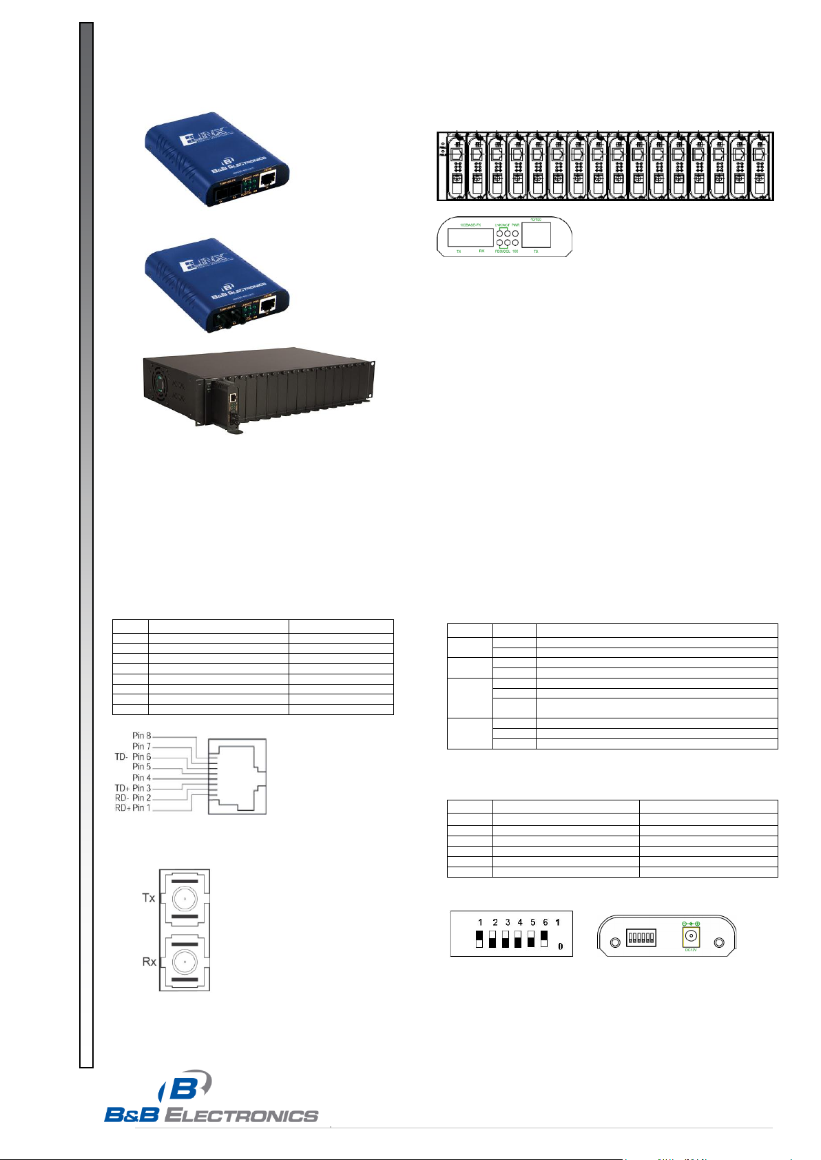
The media converter provides one channel for media conversion
between 10/100BaseTX and 100BaseFX. It can be used as a standalone device or with a standard 19 inch chassis as shown below.
Features
One-channel media conversion: 10/100BaseTX & 100BaseFX
Fiber media:
Multi-mode fiber using SC or ST connectors
Single-mode fiber using SC connectors
Auto negotiation of speed and duplex mode on TX port
Auto MDIX on TX port
DIP switch configuration for:
Link-fault-pass-through
Fixed speed
Half/full duplex
Store-and-forward mechanism
Non-blocking full wire-speed forwarding rate
Supports broadcast storm filtering
Back-pressure & IEEE802.3x compliant flow control
Front panel status LEDs
External AC to DC power adapter (included)
Used as a stand-alone device or with a chassis
Hot-swappable when used with a chassis
10/100BaseTX and 100BaseFX Connectors
10/100BaseTX Connections:
Pin
Regular Ports
Uplink Port
1
Receive Data + (input)
Transmit Data + (output)
2
Receive Data – (input)
Transmit Data – (output)
3
Transmit Data + (output)
Receive Data + (input)
4
NC
NC
5
NC
NC
6
Transmit Data – (output)
Receive Data – (input)
7
NC
NC
8
NC
NC
LED’s and DIP Switch
LED Status:
LEDs
State
Indication
PWR
Steady
Power on (PWR stands for POWER)
Off
Power off
100
Steady
100Mbps network connection
Off
10Mbps network connection
LNK/ACT
Steady
Network connection established(LNK stands for LINK)
Flashing
Transmitting or receiving data(ACT stands for ACTIVITY)
Off
Neither a network connection established nor
transmitting/receiving data
FDX/COL
Steady
Connection in full duplex mode(FDX stands for FULL-DUPLEX)
Flashing
Collision occurred(COL stands for COLLISION)
Off
Connection in half-duplex mode
DIP Switch Settings:
Pos.
DOWN (0)
UP (1)
1
Enable Link-fault-pass-through
Disable Link-fault-pass-through
2
RJ45 Auto Negotiation Enabled
RJ45 Forced Mode
3
RJ45 Forced to 100Mbps
RJ45 Forced to 10Mbps
4
RJ45 Forced to Full Duplex
RJ45 Forced to Half Duplex
5
Fiber Forced to Full Duplex
Fiber Forced to Half Duplex
6
This quick installation guide describes how to install and
use the Ethernet Media Converter and optional Rack
Chassis.
Ethernet Media Converter
& Rack Chassis
100BaseFX Connections:
The Tx (transmit) port of device 1
is connected to the Rx (receive)
port of device 2, and the Rx
(receive) port of device 1 to the Tx
(transmit) port of device 2.
Page 2
EIS series-0812qsg- 2/2
www.bb-elec.com orders@bb-elec.com support@bb-elec.com
International Office: 707 Dayton Road PO Box 1040 Ottawa, IL 61350 USA 815-433-5100 Fax 433-5104
European Office: Westlink Commercial Park Oranmore Co. Galway Ireland +353 91 792444 Fax +353 91 792445
PRODUCT INFORMATION B&B ELECTRONICS
Link-fault-pass-through
Link-Fault-Pass-Through Overview:
When two Media Converters are connected via their fiber
ports
Link Fault of the FX port:
A Link Fault condition will be sensed on the RJ45 port
whenever the media converter detects a Link Fault condition
on the Fiber port. (The 100, LNK/ACT, and FDX/COL LED’s
will be off.)
Link Fault of the TX port:
Media Converter A: A Link Fault condition will be sensed on
the Fiber port whenever the media converter detects a Link
Fault condition on the RJ45 port. Thus, the 100, LNK/ACT,
and FDX/COL LEDs of the RJ45 port of the Media Converter
A would be off.
Media Converter B: A Link Fault condition will be informed to
the Fiber port of the Media Converter B. Then a Link Fault
condition will be sensed on the RJ45 port of the Media
Converter B whenever the Media Converter B detects a Link
Fault condition on the Fiber port. Thus, the 100, LNK/ACT,
and FDX/COL LEDs of the Media Converter B would be off.
Link Fault of the FX port
TX Port
FX Port
LEDs
PWR
100
LNK/ACT
FDX/COL
LNK/ACT
FDX/COL
Media Converter A
ON
OFF
OFF
OFF
OFF
OFF
Media Converter B
ON
OFF
OFF
OFF
OFF
OFF
Link Fault of the TX port
TX Port
FX Port
LEDs
PWR
100
LNK/ACT
FDX/COL
LNK/ACT
FDX/COL
Media Converter A
ON
OFF
OFF
OFF
ON
ON
Media Converter B
ON
OFF
OFF
OFF
OFF
OFF
Rack Chassis Specifications
Features:
• House up to 16 media converters
• Front panel LED’s for power status
• Standard 19 inch Rack, 2U size
• Hot-swappable: Media converters and Power supplies
• Cooling fans for ventilation - one on right & left sides of chassis
• Ventilation holes on each side
• Load sharing mechanism:
If one power supply fails, the other takes over immediately
• Each converter bay is electrically isolated from each other
• Over current protection
Fuses on PCB for each converter bay
Fuses on each power supply
Chassis Specifications:
Capacity
Houses up to 16 media converters
Power
One power supply included, second optional
hot-swappable
Cooling
One fan on the left and right side of the chassis
LED Indicators
One LED for each power supply’s power status)
Dimensions
17.3 x 10.9 x 3.5 in (44 x 27.6 x 9 cm)
Standard 19 inch, 2U size
Net Weight
8.5kg approx. (with sixteen media converters)
Power Supply Specifications:
Power Input
110 to 240VAC, 50/60Hz
Power Output
12VDC, 84W max.
Load
7A max.
Operating Temp
0°C to 40° C (32°F to 104°F)
Storage Temp
-25°C to 70°C (-13°F to 158°F)
Emissions
FCC Part 15 Class A; CE Class A
Installation
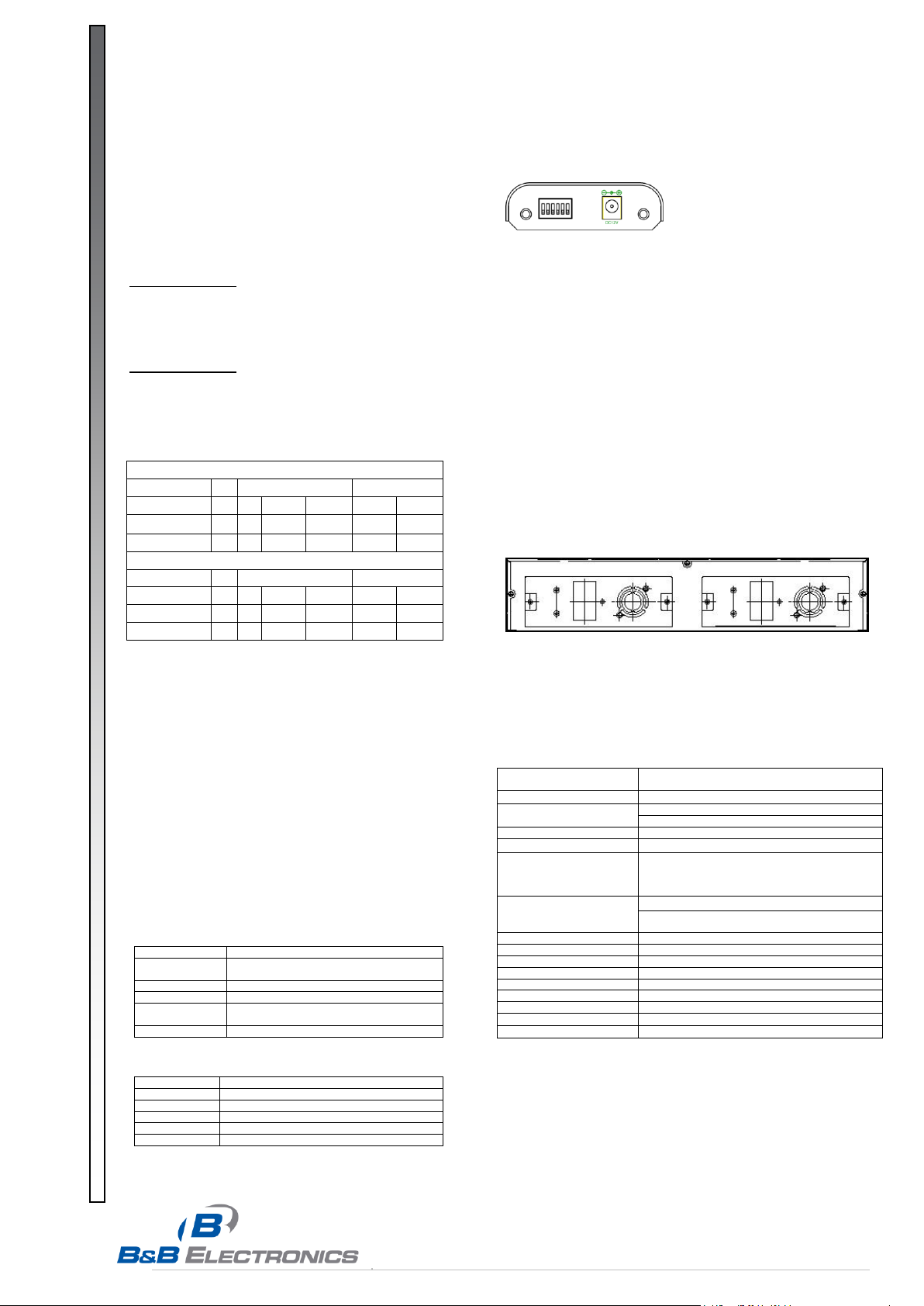
Connecting Power:
The media converter is a plug-and-play device, so simply plug the
power supply into the converter and then the AC outlet.
Installing the Media Converter into the Chassis:
The media converter fits into any of the chassis expansion slots.
First, remove one of the expansion slot carriers
Then, install the converter onto the carrier
Next, insert the carrier onto the guide rails of the expansion slot
Carefully slide the carrier unit in, until it firmly fits the chassis
Reinstall the screw that locks the carrier to the chassis
Installing the Power Supply into the Chassis:
The power supply fits into either of the two power supply bays on
the back of the rack chassis.
First, remove the cover plate
Then, insert the power supply into the guide rails of the bay
Carefully slide the power supply in until it firmly fits in the chassis
Tighten the thumb screws provided on the power supply
Media Converter Specifications
Applicable Standards
IEEE 802.3 10BaseT,
IEEE 802.3u 100BaseTX & 100BaseFX
Fixed Ports
(1) TX port, (1) FX port
Speed 10BaseT
100BaseTX/FX
10/20Mbps for half/full-duplex
100/200Mbps for half/full-duplex
Switching Method
Store-and-Forward
Forwarding rate
14,880/148,800pps for 10/100Mbps
Cable
10BaseT
100BaseTX
100BaseFX
2-pair UTP/STP Cat. 3, 4, 5 up to 100m
2-pair UTP/STP Cat. 5 up to 100m
MMF (50 or 62.5μm), SMF (9 or 10μm)
LED Indicators
Per Unit - PWR1, PWR2, FAULT, LFP
Per Port - TX: LNK/ACT, FDX/COL, 100
FX: LNK/ACT, FDX/COL
Dimensions
4.3 x 3.2 x 0.9 in. (10.9 x 8 x 2.4 cm)
Weight
0.15 Kg
Power
External Power Supply 12VDC @ 280mA
Power Consumption
3.4W
Operating Temperature
0°C to 50°C
Storage Temperature
-25°C to 70°C
Humidity
10 to 90%, non-condensing
Emissions
FCC Part 15, Class A; CE
Safety
UL/CUL 60950, EN60950, IEC 60950, IEC61000-6-2
 Loading...