

Page 1
Product Overview
Plug In Your Cable
3
4
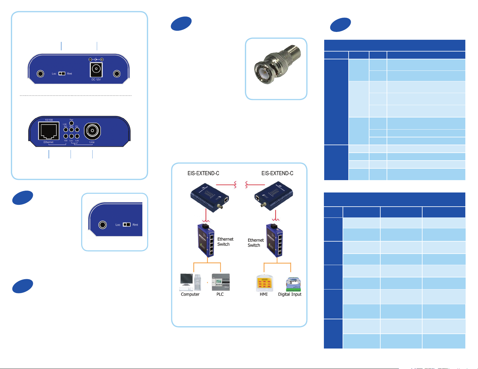
LED Status
Rear View
DIP Switch
Front View
Ethernet LEDs
Set DIP Switch
1
Ethernet extenders work
in pairs. Set one as the
local (Loc) unit and the
other as the remote (Rem)
unit. It doesn’t matter which
one is which.
12 VDC
Coax Line
The DIP switch is on top of the device.
Connect the Ethernet cable
to the RJ-45 port on the front
of the Ethernet extender.
Connect the coaxial cable
to the BNC port on the front
of the Ethernet extender. The
opposite end connects with
a paired Ethernet extender
located elsewhere. Coax
cable must be terminated
with male BNC to F
connectors. A BNC to F-Type
adaptor is required for the F
style connector (included).
BNC to F-Type Adaptor
Front Panel LEDs (Ethernet and Line Connections)
Port LEDs Status Description
Ethernet
(RJ-45)
Line (BNC) Remote Steady Operating in remote mode
Top LEDs (BNC Line Connections)
LED Status Speed Distance
1
2
Power1
Power2
Power3
Link/ACT
FDX
Local Steady Operating in local mode
Error Steady Error occurred
Link
Green 1-5 Mbps up to 2600 M
Amber 6-10 Mbps up to 2400 M
Green 11-16 Mbps up to 2000 M
Amber 17-20 Mbps up to 1800 M
Steady Power on
Off Power off
Steady Valid Ethernet connection established
Flashing Transmitting or receiving Ethernet data
(ACT stands for Activity)
Off No valid Ethernet connection nor transmitting/
receiving Ethernet data
Steady Ethernet connection in full duplex mode
(FDX stands for FULL-DUPLEX)
Flashing Collision occurred
Off Ethernet connection in half-duplex mode
Steady A valid connection established between local
and remote
Connect Your Power Supply
2
Apply rubber feet to the bottom of the media
converter and select a suitable mounting location. The
unit can be wall-mounted using the slots on the bottom
of the case.
Connect the supplied AC to DC power adaptor to the
receptacle on the rear panel of the Ethernet extender.
Note: Extender must be connected to a receiving extender
or a network switch.
Green 21-29 Mbps up to 1600 M
3
Amber 30-43 Mbps up to 1400 M
Green 44-54 Mbps up to 1200 M
4
Amber 55-63 Mbps up to 1000 M
Green 64-74 Mbps up to 600 M
5
Amber 75-85 Mbps up to 200 M
Page 2
Troubleshooting
Self-diagnostic Test Procedure
1. Two Ethernet extenders are connected, as a pair,
using BNC connectors over coaxial cable.
2. One Ethernet extender is configured as a local
unit. The setting mode switch on the rear panel of this
Ethernet extender is set to Loc (local mode), and is
located at the local end of the Ethernet extension.
3. The other Ethernet extender is configured as the
remote unit. The setting mode switch on the rear
panel of this Ethernet extender is set to Rmt (remote
mode), and is located at the remote end of the Ethernet
extension.
4. Supplied AC to DC power adaptors are connected
to the receptacles on the rear panel of both Ethernet
extenders. Both adapters are plugged into standard
AC outlet sockets.
5. LED 5 on the top panel of both Ethernet extenders
lights up in an amber or green color, showing
that both Ethernet extenders are connected and
have negotiated best performance for symmetrical
transmission.
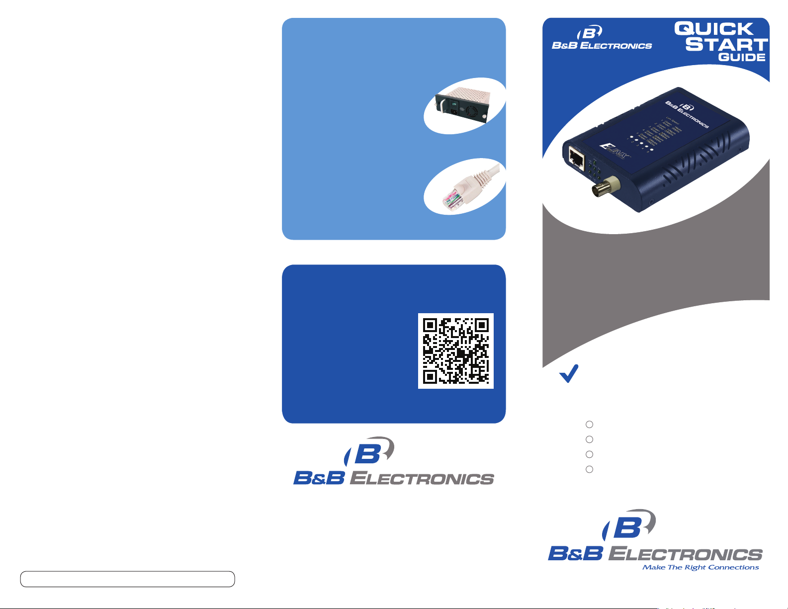
Recommended Accessories
and Power Supplies
Power Supply for EIS-RACK-16,
84 Watts
http://www.bb-elec.com/
EIS - EXTEND - C/AC C
CAT 5 Cable
http://www.bb-elec.com/
EIS - EXTEND - C/AC C
Fast, Easy Answers
• First, check step 4.
• Then use your smart
phone to access complete
documentation on our
web site. Simply scan
the code to the right.
http://www.bb-elec.com/EIS-EXTEND-C
EIS-RACK-PS
CAT 5 Cable
EIS-EXTEND-C
Ethernet Coaxial Extender
First Things First...
Before you begin, be sure you have
the following:
Ethernet Coaxial Extender
AC to DC Power Adaptor
Rubber Feet
BNC to F-Type Adaptor
Document number – p/n r002 EIS-EXTEND- C - 1712
1-888-948-2248 | Europe: +353 91 792444
www.bb-elec.com
707 Dayton Road | PO Box 1040 | Ottawa, IL 61350
Phone: 815-433-5100 | Fax: 815-433-5109
www.bb-elec.com | E-mail: info@bb-elec.com
© 2012 B&B Elect ronics Manuf acturing Co mpany
Fast and easy on the web:
www.bb-elec.com
 Loading...