

Page 1
Quick Start Guide
Elinx PoE Managed Ethernet Switch
EIRP610-2SFP-T
1
Items Included
o Ethernet Switch
o Console Cable (RS-232 RJ-45 to DB-9)
o CD with Support Manual
o This Quick Start Guide
o Panel Mount Bracket
2
Default Settings
o IP Address: 192.168.16.1
o Subnet Mask: 255.255.255.0
o Gateway: 192.168.16.254
o User Name: root, Password: root
3
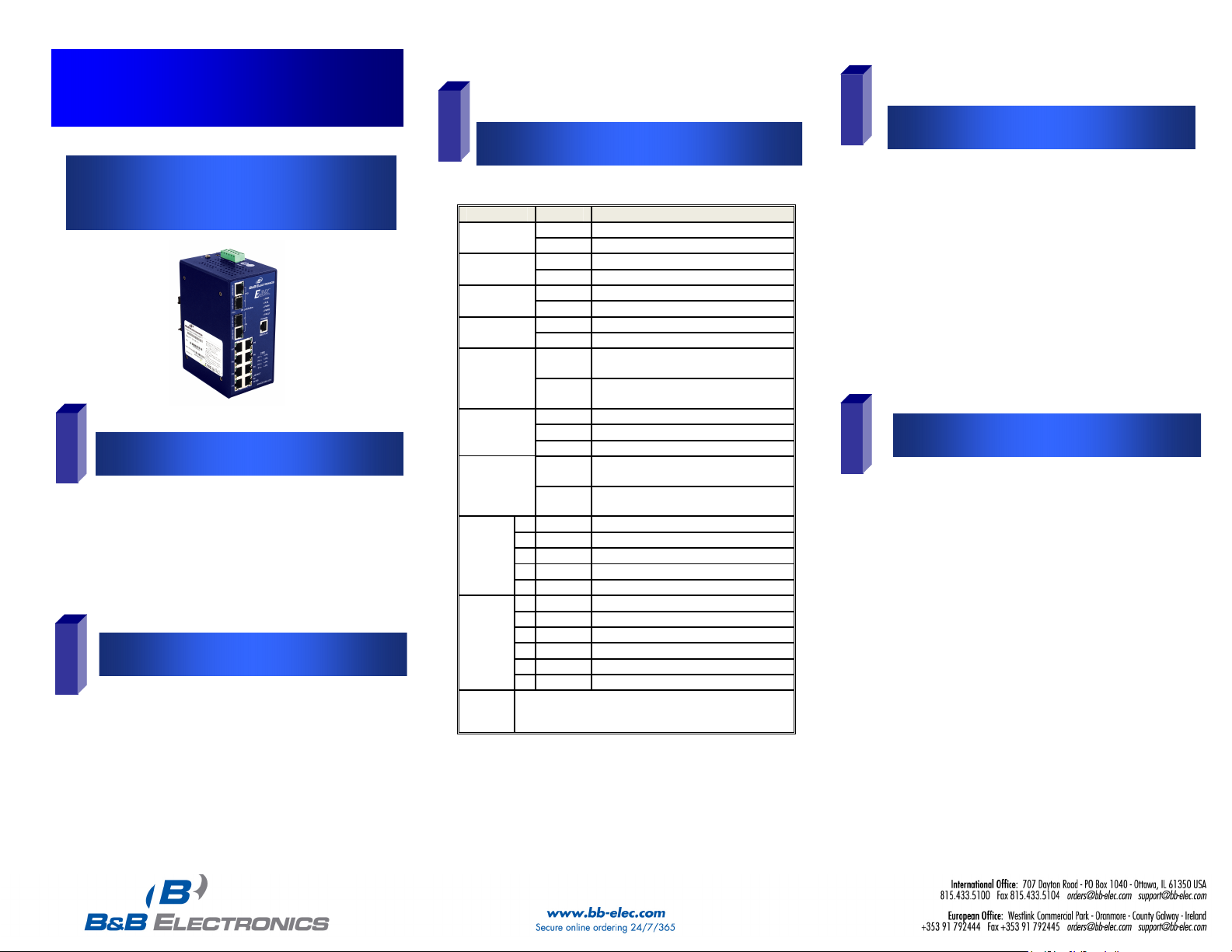
LED Status Description
PWR
PWR1
PWR2
Fault
R.M
Ports 9, 10
LNK/ACT
(SFP)
FWD
P1 to P8
Ports
9, 10
(RJ-45)
Ports
1 to 8
(PoE)
Note
Green The Switch is powered on
Off The Switch is powered off
Green Power Source 1 is available
Off Power Source 1 is unavailable
Green Power Source 2 is available
Off Power source 2 is unavailable
Red Power or Port failure
Off Normal Operation
Green
Off
Green SFP Port is linked
Blinking Data is being transmitted or received
Off Not connected to the network
Green
Off
T Green Port is linked
T Blinking Data is being transmitted or received
T Off Not connected to the network
B Green Operating at 1000M
B
Off Disconnected or 10/100M
T Green Connected to the network
T Blinking Data is being transmitted or received
T Off Not connected to the network
B Yellow Operating in full-duplex
B Blinking Data collision
B
Off Half-duplex or not connected
Ports 1 to 8 are 10/100 PoE RJ-45, Ports 9 and 10 are
10/100/1000 RJ-45 or 100/1000 SFP.
LED Chart
The Switch is the master of a redundant
ring (X-Ring)
The Switch is not the master of a
redundant ring.
The port is supplying power to the
connected device
No device attached or no power is being
supplied
EIRP610-2SFP-T-1012qsg
4
Hardware Installation
o You should provide your Network Administrator with
your switch’s MAC address. You should get your IP
Address, Subnet Mask and Gateway information from
your Network Administrator. NOTE: The switch’s
MAC Address is located on the products side label.
o Select a mounting location and install with the attached
DIN rail clip or included panel mount kit.
o Connect power to the switch
o 48 VDC
o Redundant inputs are available with fault
contacts.
NOTE: The installation of an SFP Module disables
the associated RJ-45 Port.
5
o These instructions are for Web based management.
Refer to the User’s Manual for instructions concerning
console management.
o Connect a switch port to a stand alone PC. Change the
PC’s network IP Address to allow it to connect to the
switch (ex: 192.168.16.2). Use the default subnet mask
and gateway.
o Launch the PC’s web browser and navigate to the
switch by typing the switch’s IP Address in the browsers
address window.
o Navigate the web page by expanding the folders on the
web page.
Log into the Switch
Page 2
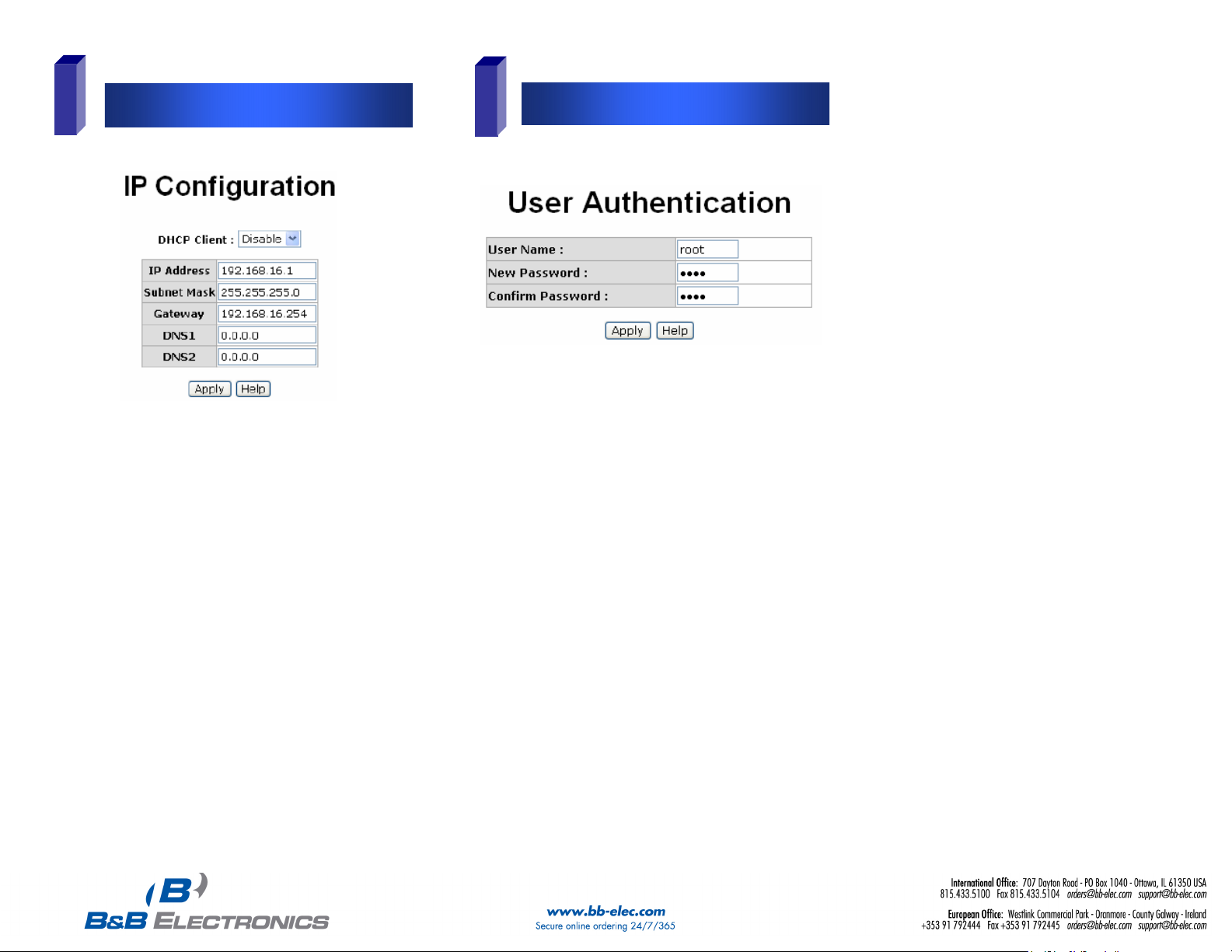
6
o Expand the “system tree” and select IP configuration.
o Enter the IP Address, Subnet Mask, and Gateway
provided by your Network Administrator.
o Save changes.
o Disconnect the stand alone PC and connect the switch
to the network.
o Inform your Network Administrator that the IP Address
has been changed.
o NOTE: The User Manual contains instructions for
assigning the IP Address from a DHCP Server and
allowing the switch to be a DHCP Server.
IP Configuration
7
o
o
o This step should be accomplished by the Network
Administrator.
o Log onto the switch from a Network PC.
o Expand the “System Tree” and select user
authentication..
o Enter the new User Name and Password. Record this
information in the space provided below. File this
document for future reference.
o Click the Apply button.
USER NAME: _____________________________________
PASSWORD:_____________________________________
MAC ADDRESS: __________________________________
IP ADDRESS: _____________________________________
User Name and Password
EIRP610-2SFP-T1012qsg
Basic Configuration is complete. A
comprehensive Manual is contained on the CD
ROM. Refer to this manual to configure the
advanced features of this switch.
 Loading...