

Page 1
Quick Start Guide
Elinx PoE Ethernet Switch
EIRP410-2SFP-T
Items Included
1
2
3
LED Chart
Ports
Log into the Switch
5
4
LED
Status
Description
PWR
Green
The Switch is powered on
Off
The Switch is powered off
PWR1
Green
Power Source 1 is available
Off
Power Source 1 is unavailable
PWR2
Green
Power Source 2 is available
Off
Power source 2 is unavailable
Fault
Red
Power or Port failure
Off
Normal Operation
R.M
Green
The Switch is the master of a redundant ring
(X-Ring)
Off
The Switch is not the master of a redundant
ring.
Ports 9, 10
LNK/ACT
(SFP)
Green
SFP Port is linked
Blinking
Data is being transmitted or received
Off
Not connected to the network
FWD
P1 to P8
Green
The port is supplying power to the connected
device
Off
No device attached or no power is being
supplied
Ports
9, 10
(RJ-45)
T
Green
Port is linked
T
Blinking
Data is being transmitted or received
T
Off
Not connected to the network
B
Green
Operating at 1000M
B
Off
Disconnected or 10/100M
T
Green
Connected to the network
T
Blinking
Data is being transmitted or received
T
Off
Not connected to the network
B
Yellow
Operating in full-duplex
B
Blinking
Data collision
B
Off
Half-duplex or not connected
Note
Ports 1 to 8 are 10/100 PoE RJ-45, Ports 9 and 10 are
10/100/1000 RJ-45 or 100/1000 SFP.
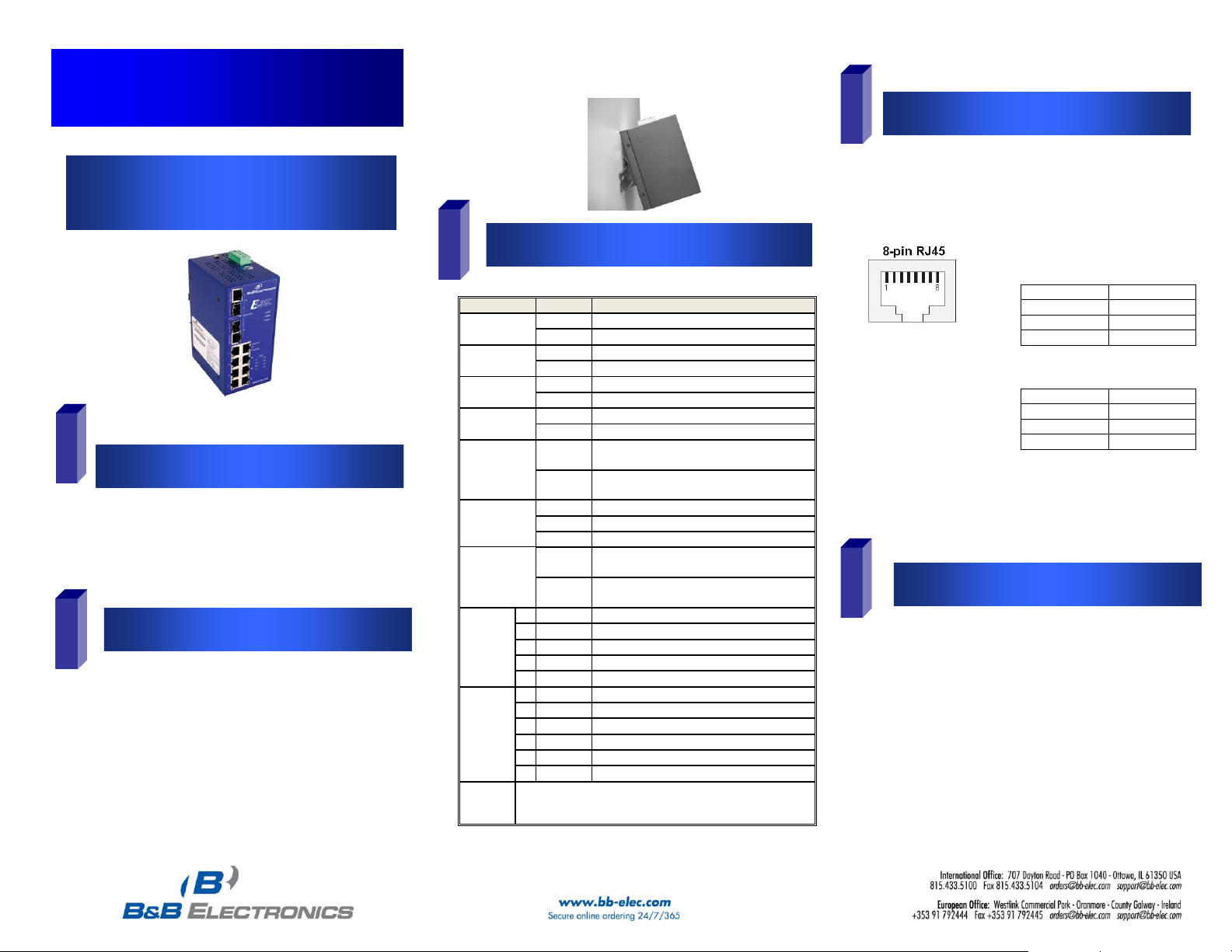
MDI Cable Pinout
Pin
Signal 1 Tx+ 2 Tx- 3 Rx+
6
Rx-
MDI-X Cable Pinout
Pin
Signal
1
Rx+
2
Rx-
3
Tx+ 6 Tx-
Hardware Installation
o Ethernet Switch
o CD with Support Manual
o This Quick Start Guide
o Panel Mount Bracket
1. Select a mounting location and install the
switch onto a piece of DIN rail or use the
included panel mount brackets for wall or
panel mounting
2. Connect power to the switch
48 VDC
EIRP410-2SFP-T-0912qsg
For redundancy connect two separate power supplies
using the two DC inputs on the terminal blocks
If only one power input is used the Fault LED will light.
RJ-45 ports: The RJ-45 ports auto-sense for 10 or 100 Mbps
device connections. The auto MDI/MDIX feature allows
connections to switches, workstation and other equipment
without changing straight through or crossover cabling. The
charts below show the cable pin assignments for straight
through and crossover cables.
PoE ports: The PoE ports on this switch follow Alternative A
standards and are limited to 15.4 Watts of power output per
port. Ports 1 thru 4 support the IEEE802.3af standard and
are classified as (PSE) power sourcing equipment, which
means they can be used to power (PD) powered devices.
1. Once power is applied and devices connected, the
switch will automatically discover standard and PoE
network devices.
 Loading...