

Page 1
EIRP305-24V-T-3412qsg
Quick Start Guide
Elinx PoE Ethernet Switch
EIRP305-24V-T
Items Included
1
2
Hardware Installation
3
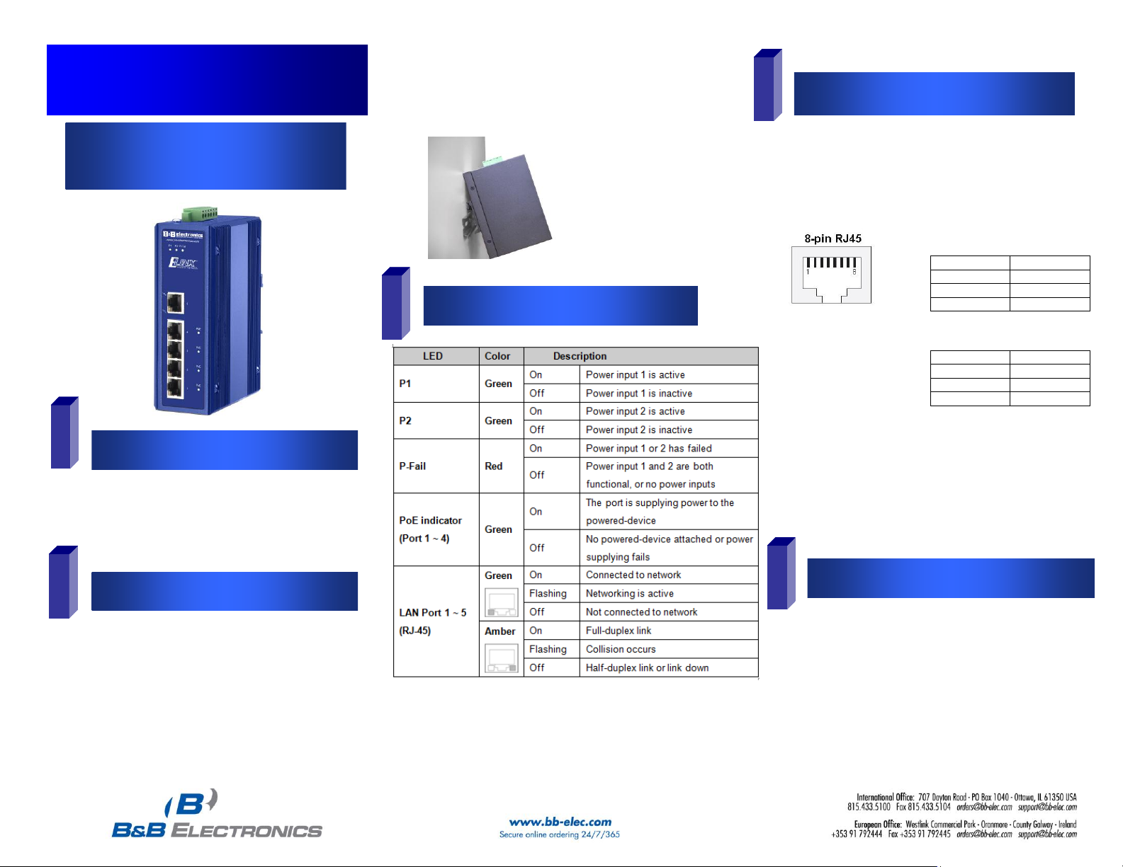
LED Chart
4
Ports
5
Installation Complete
MDI Cable Pinout
Pin
Signal
1
Tx+ 2 Tx-
3
Rx+
6
Rx-
MDI-X Cable Pinout
Pin
Signal
1
Rx+ 2 Rx-
3
Tx+
6
Tx-
1. Auto MDI/MDI-x is
supported. A straight
through or cross-over
cable may be used.
2. 10/100 auto
negotiation and full/halfduplex are supported.
1. Once power is applied and devices
connected, the switch will automatically
discover standard and PoE network
devices.
If redundancy is desired be sure to
connect two separate power supplies by
using the two DC inputs on the terminal
blocks
If only one power input is used the Fault
LED will light (this is normal)
o Ethernet Switch
o CD with Support Manual
o This Quick Start Guide
o Panel Mount Bracket
1. Select a mounting location and install the
switch onto a piece of DIN rail or use the
included panel mount brackets for wall or
panel mounting
2. Connect power to the switch
24 or 48 VDC
RJ-45 ports: The RJ-45 ports auto-sense for 10 or 100 Mbps
device connections. The auto MDI/MDIX feature allows
connections to switches, workstation and other equipment
without changing straight through or crossover cabling. The
charts below show the cable pin assignments for straight
through and crossover cables.
PoE ports: The PoE ports on this switch follow Alternative A
standards and are limited to 15.4 Watts of power output per
port. Ports 1 thru 4 support the IEEE802.3af standard and
are classified as (PSE) power sourcing equipment, which
means they can be used to power (PD) powered devices.
 Loading...