

Page 1
User Manual
Elinx EIRM-EXTEND
Managed Hardened 10/100BASE-TX
Ethernet Extender
Manual Documentation Number: EIRM-EXTEND-1412m Table of Contents i
B&B Electronics Mfg Co Inc – 707 Dayton Rd - PO Box 1040 - Ottawa IL 61350 - Ph 815-433-5100 - Fax 815-433-5104 – www.bb-elec.com
B&B Electronics – Westlink Commercial Park – Oranmore, Galway, Ireland – Ph +353 91-792444 – Fax +353 91-792445 – www.bb-europe.com
Documentation Number: EIRM-EXTEND-0411m
Model EIRM-EXTEND
Page 2

707 Dayton Road -- P.O. Box 1040 -- Ottawa, IL 61350 USA
Phone (815) 433-5100 -- General Fax (815) 433-5105
Website: www.bb-elec.com
Sales e-mail: orders@bb-elec.com
Technical Support e-mail: support@bb.elec.com
European Headquarters
B&B Electronics
Westlink Commercial Park -- Oranmore, Co. Galway, Ireland
Phone +353 91-792444 -- Fax +353 91-792445
Website: www.bb-europe.com
Sales e-mail: sales@bb-europe.com
Technical Support e-mail: support@bb-europe.com
B&B Electronics Mfg. Co. Inc.
-- Fax (815) 433-5109
-- Fax (815) 433-5104
B&B Electronics Mfg Co Inc – 707 Dayton Rd - PO Box 1040 - Ottawa IL 61350 - Ph 815-433-5100 - Fax 815-433-5104 – www.bb-elec.com
B&B Electronics – Westlink Commercial Park – Oranmore, Galway, Ireland – Ph +353 91-792444 – Fax +353 91-792445 – www.bb-europe.com
Page 3

This document contains information that is proprietary and confidential to B&B
Electronics Mfg. Co. Inc. The methods described herein are for the exclusive use of
B&B Electronics authorized personnel. Any unauthorized use or dissemination of the
information contained in the document is strictly forbidden.
Manual Documentation Number: EIRM-EXTEND-1412m Table of Contents iii
B&B Electronics Mfg Co Inc – 707 Dayton Rd - PO Box 1040 - Ottawa IL 61350 - Ph 815-433-5100 - Fax 815-433-5104 – www.bb-elec.com
B&B Electronics – Westlink Commercial Park – Oranmore, Galway, Ireland – Ph +353 91-792444 – Fax +353 91-792445 – www.bb-europe.com
Page 4

Table of Contents
Chapter 1 – Introduction 1
PRODUCT OVERVIEW ................................................................................ 1
PRODUCT FEATURES ................................................................................. 1
PACKING LIST ........................................................................................... 2
One-Channel Hardened Managed Ethernet Extender 3
PORTS ....................................................................................................... 3
ETHERNET EXTENDER MODE SETTINGS .................................................... 3
DIP SWITCH .............................................................................................. 3
FRONT PANEL & LEDS ............................................................................. 4
Installation 6
SELECTING A SITE FOR THE EQUIPMENT ................................................... 6
WIRING DIAGRAM ..................................................................................... 6
DIN RAIL MOUNTING ............................................................................... 7
CONNECTING TO POWER ........................................................................... 8
12VDC DC Jack ................................................................................... 8
Redundant DC Terminal Block Power Inputs ...................................... 8
Chapter 2 – Web-Based Browser Management 9
LOGGING IN TO THE HARDENED MANAGED ETHERNET EXTENDER .......... 9
IP Address ............................................................................................ 9
Password .............................................................................................. 9
UNDERSTANDING THE BROWSER INTERFACE .......................................... 10
BASIC SETTINGS ...................................................................................... 11
Network Settings ................................................................................. 11
Server Name Settings .......................................................................... 12
NTP Server Settings ............................................................................ 13
ADVANCED SETTINGS ............................................................................. 13
Lan Settings ........................................................................................ 14
VDSL Settings ..................................................................................... 14
SNMP Settings .................................................................................... 17
Link-Fault-Pass-Through Settings ..................................................... 18
Log Settings ........................................................................................ 18
SYSTEM MANAGEMENT .......................................................................... 18
Save Configuration ............................................................................. 19
Change Password ............................................................................... 19
Accessible List .................................................................................... 20
Restore Factory Default ..................................................................... 20
Firmware Upgrade ............................................................................. 21
Reset VDSL ......................................................................................... 21
B&B Electronics Mfg Co Inc – 707 Dayton Rd - PO Box 1040 - Ottawa IL 61350 - Ph 815-433-5100 - Fax 815-433-5104 – www.bb-elec.com
B&B Electronics – Westlink Commercial Park – Oranmore, Galway, Ireland – Ph +353 91-792444 – Fax +353 91-792445 – www.bb-europe.com
Page 5

Retrain VDSL ..................................................................................... 22
System Log .......................................................................................... 23
VDSL Status ........................................................................................ 24
RESTART ................................................................................................. 24
Restart System .................................................................................... 24
Chapter 3 – Command Line Console Management 25
SYSTEM MANAGEMENT .......................................................................... 26
SYSTEM MANAGEMENT .......................................................................... 29
ETHERNET EXTENDER MANAGEMENT .................................................... 32
NETWORK MANAGEMENT ....................................................................... 33
NET-SNMP 34
Specifications 36
NET-SNMP 38
Manual Documentation Number: EIRM-EXTEND-1412m Table of Contents v
B&B Electronics Mfg Co Inc – 707 Dayton Rd - PO Box 1040 - Ottawa IL 61350 - Ph 815-433-5100 - Fax 815-433-5104 – www.bb-elec.com
B&B Electronics – Westlink Commercial Park – Oranmore, Galway, Ireland – Ph +353 91-792444 – Fax +353 91-792445 – www.bb-europe.com
Page 6

B&B Electronics Mfg Co Inc – 707 Dayton Rd - PO Box 1040 - Ottawa IL 61350 - Ph 815-433-5100 - Fax 815-433-5104 – www.bb-elec.com
B&B Electronics – Westlink Commercial Park – Oranmore, Galway, Ireland – Ph +353 91-792444 – Fax +353 91-792445 – www.bb-europe.com
Page 7
Chapter 1 – Introduction
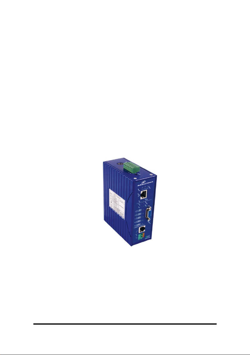
The Hardened Managed Ethernet Extender provides one channel Ethernet over
existing voice grade copper wire. This Hardened Managed Ethernet Extender solution
is perfectly fitted in the industrial applications or rugged environment.
Product Overview
Product Features
• Meets NEMA TS1/TS2 Environmental requirements: temperature, shock, and
vibration for traffic control equipment.
• Meets EN61000-6-2 & EN61000-6-4 EMC Generic Standard Immunity for
industrial environment.
• Operates transparent to higher layer protocols such as TCP/IP.
• Ethernet port: Supports IEEE802.3/802.3u/802.3x. Auto-negotiation:
10/100Mbps, full/half-duplex; Auto MDI/MDIX.
• Ethernet Extender port: Asymmetrical or Symmetrical on the VDSL, full-duplex
59/31Mbps (downstream/upstream) asymmetrical or full-duplex 50Mbps
symmetrical communications link over existing copper telephone line.
• One DIP switch for configuring Local (Loc) and Remote (Rmt).
• Ten speeds with speed indicator LEDs on front panel of unit, up to 50Mbps @
about 300meters (984ft.), down to 1Mbps @ about 1,900meters (6,233ft.).
• Supports RS-232 console, SNMP, Web Browser management.
• Operating voltage and Max. current consumption: 0.5A @ 12VDC, 0.25A @
24VDC. Power consumption: 6W Max.
• Power Supply: Redundant 12-32VDC Terminal Block power inputs and 12VDC
DC JACK with 100-240VAC external power supply.
Manual Documentation Number: EIRM-EXTEND-1412m 1
B&B Electronics Mfg Co Inc – 707 Dayton Rd - PO Box 1040 - Ottawa IL 61350 - Ph 815-433-5100 - Fax 815-433-5104 – www.bb-elec.com
B&B Electronics – Westlink Commercial Park – Oranmore, Galway, Ireland – Ph +353 91-792444 – Fax +353 91-792445 – www.bb-europe.com
Page 8

• Field Wiring Terminal: Use Copper Conductors Only, 12-24 AWG torque value 7
lb-in.
• Operating temperature range @ -40℃ to 75℃ (-40℉ to 167℉).
Tested for functional operation @ -40℃ to 85℃ (-40℉ to 185℉).
UL508 Industrial Control Equipment certified Maximum Surrounding Air
Temperature @ 75℃ (167℉).
• For use in Pollution Degree 2 Environment.
• Supports Din-Rail or Panel Mounting installation.
Packing List
Please inspect the contents listed below, report any apparent damage or missing
items immediately to our authorized reseller.
The Hardened Managed Ethernet Extender
•
• User’s Manual
• AC to DC Power Adaptor and Power Cable (optional)
2 Manual Documentation Number: EIRM-EXTEND-1412m
B&B Electronics Mfg Co Inc – 707 Dayton Rd - PO Box 1040 - Ottawa IL 61350 - Ph 815-433-5100 - Fax 815-433-5104 – www.bb-elec.com
B&B Electronics – Westlink Commercial Park – Oranmore, Galway, Ireland – Ph +353 91-792444 – Fax +353 91-792445 – www.bb-europe.com
Page 9

One-Channel Hardened Managed Ethernet Extender
Ports
The Hardened Managed Ethernet Extender provides one Ethernet port RJ-45
(10/100Mbps) port and one Ethernet Extender port.
The Ethernet Extender port, uses RJ-11 and Terminal Block connectors that will auto
senses the speeds 1/3/5/10/15/20/25/30/40/50Mbps.
Ethernet Extender Mode Settings
Ethernet Extender mode settings are DIP switch (Dual Inline Package) selectable.
The switch is located on the top panel of the Hardened Managed Ethernet Extender.
DIP switch
There is one pin on the DIP switch for Ethernet Extender mode settings.
One unit must be set to LOC and one to RMT.
Loc Rmt
The device operates in local mode The device operates in remote mode
Manual Documentation Number: EIRM-EXTEND-1412m 3
B&B Electronics Mfg Co Inc – 707 Dayton Rd - PO Box 1040 - Ottawa IL 61350 - Ph 815-433-5100 - Fax 815-433-5104 – www.bb-elec.com
B&B Electronics – Westlink Commercial Park – Oranmore, Galway, Ireland – Ph +353 91-792444 – Fax +353 91-792445 – www.bb-europe.com
Page 10

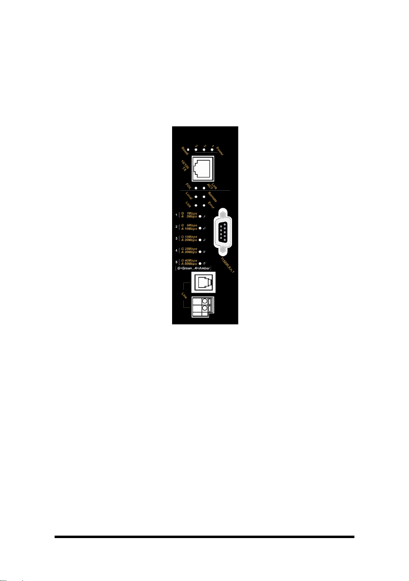
Front Panel & LEDs
LED Indicators
The LED indicators give you instant feedback on status of the Hardened Managed
Ethernet Extender:
LEDs State Indication
Power 1
Power 2
Power 3
Ethernet
Link/ACT
FDX
Ethernet Extender
1
2
3
4
5
Remote Steady The device operates in remote mode
Local Steady The device operates in local mode
Error Steady Error occurred
Link Steady A valid connection established
Steady Power on
Off Power off
Steady A valid Ethernet connection established
Flashing
Off
Steady
Off Ethernet Connection in half-duplex mode
Green
Amber
Green
Amber
Green
Amber
Green
Amber
Green
Amber
Transmitting or receiving Ethernet data
ACT stands for ACTIVITY
Neither valid Ethernet connection established nor
transmitting/receiving Ethernet data
Ethernet Connection in full-duplex mode
FDX stands for FULL-DUPLEX
The Ethernet Extender port transmitting/receiving at 1Mbps,
up to 1900M
The Ethernet Extender port transmitting/receiving at 3Mbps,
up to 1800M
The Ethernet Extender port transmitting/receiving at 5Mbps,
up to 1600M
The Ethernet Extender port transmitting/receiving at 10Mbps,
up to 1400M
The Ethernet Extender port transmitting/receiving at 15Mbps,
up to 1200M
The Ethernet Extender port transmitting/receiving at 20Mbps,
up to 1000M
The Ethernet Extender port transmitting/receiving at 25Mbps,
up to 800M
The Ethernet Extender port transmitting/receiving at 30Mbps,
up to 700M
The Ethernet Extender port transmitting/receiving at 40Mbps,
up to 600M
The Ethernet Extender port transmitting/receiving at 50Mbps,
up to 300M
4 Manual Documentation Number: EIRM-EXTEND-1412m
B&B Electronics Mfg Co Inc – 707 Dayton Rd - PO Box 1040 - Ottawa IL 61350 - Ph 815-433-5100 - Fax 815-433-5104 – www.bb-elec.com
B&B Electronics – Westlink Commercial Park – Oranmore, Galway, Ireland – Ph +353 91-792444 – Fax +353 91-792445 – www.bb-europe.com
Page 11
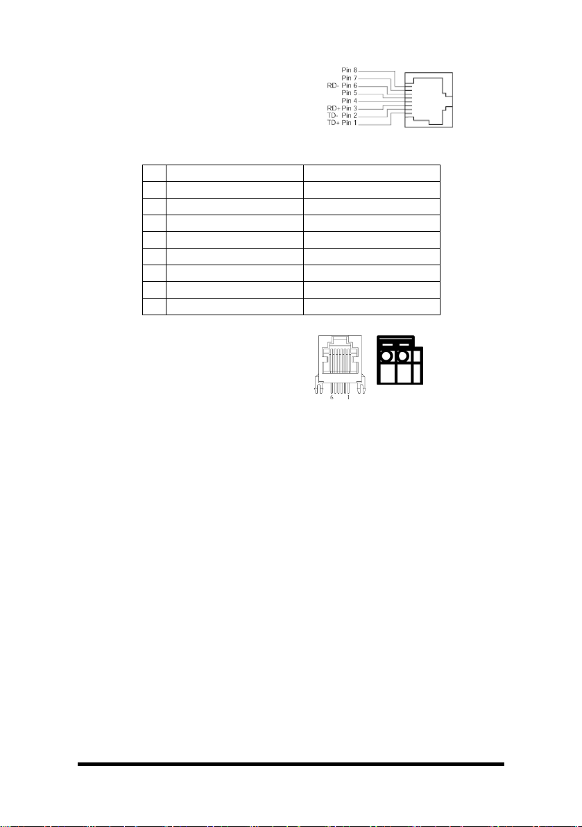
The 10/100Base-TX and Ethernet Extender Connectors
The 10/100Base-TX Connection
The following lists the pinouts of
10/100Base-TX RJ-45 port.
Pin Regular Ports Uplink ports
1 Output Transmit Data + Input Receive Data +
2 Output Transmit Data - Input Receive Data 3 Input Receive Data + Output Transmit Data +
4 NC NC
5 NC NC
6 Input Receive Data - Output Transmit Data 7 NC NC
8 NC NC
The Ethernet Extender Connection
The RJ-11 and Terminal Block port
pinouts:
Pin 3: Tip, Pin 4: Ring.
Use a telephone line to connect two RJ-11
or Terminal Block ports between two
Hardened Ethernet Extenders.
Connections are straight through or
crossover.
Warning: Inappropriate operation might cause the damage of Terminal Block.
Tip Ring
Manual Documentation Number: EIRM-EXTEND-1412m 5
B&B Electronics Mfg Co Inc – 707 Dayton Rd - PO Box 1040 - Ottawa IL 61350 - Ph 815-433-5100 - Fax 815-433-5104 – www.bb-elec.com
B&B Electronics – Westlink Commercial Park – Oranmore, Galway, Ireland – Ph +353 91-792444 – Fax +353 91-792445 – www.bb-europe.com
Page 12
Installation
This chapter gives step-by-step installation instructions for the Hardened Managed
Ethernet Extender.
Selecting a Site for the Equipment
As with any electric device, you should place the equipment where it will not be
subjected to extreme temperatures, humidity, or electromagnetic interference.
Specifically, the site you select should meet the following requirements:
• The Surrounding Air temperature should be between -34 to 60 degrees
Celsius.
• The relative humidity should be less than 95 percent, non-condensing.
• Surrounding electrical devices should not exceed the electromagnetic
field (RFC) standards.
• Make sure that the equipment receives adequate ventilation. Do not
block the ventilation holes of the equipment.
• The power outlet should be within 1.8 meters of the product.
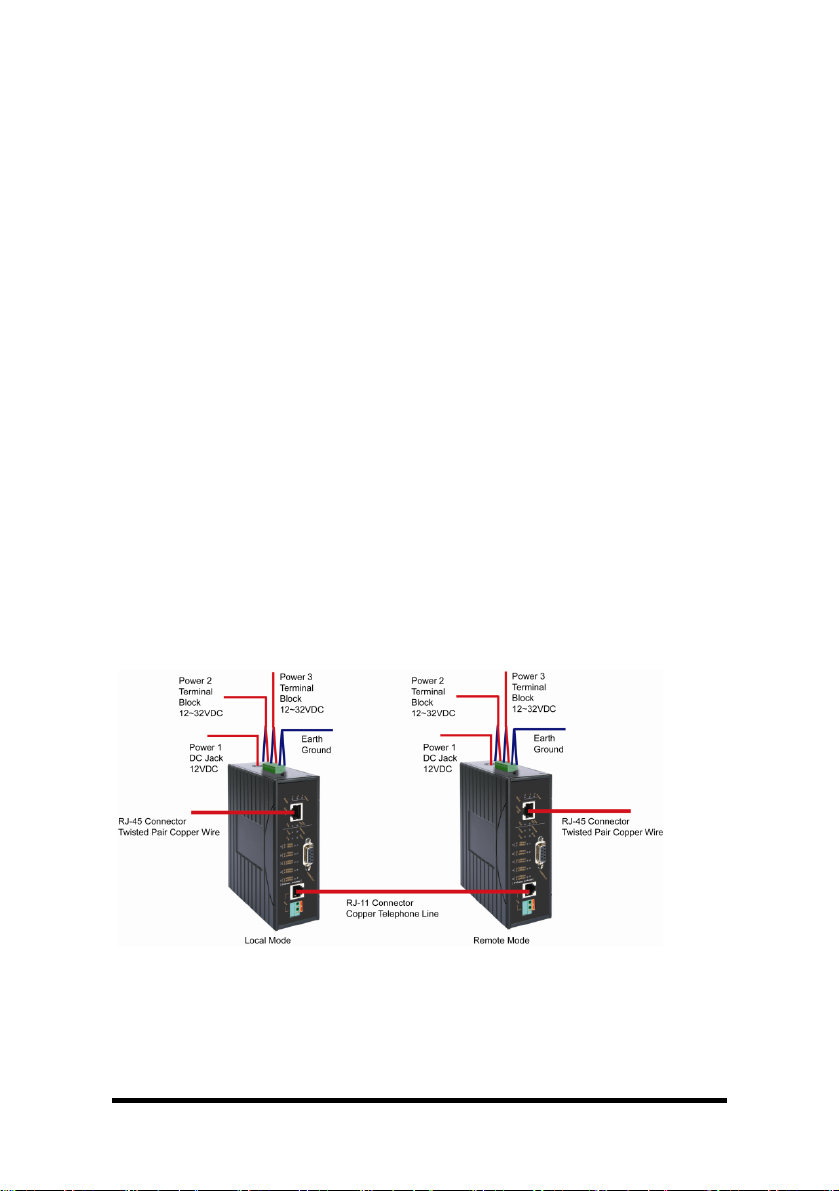
Wiring Diagram
Field Wiring Terminal Markings: Use Copper Conductors Only, 60/75℃,
wire range 12-24 AWG, torque value 7 lb-in.
6 Manual Documentation Number: EIRM-EXTEND-1412m
B&B Electronics Mfg Co Inc – 707 Dayton Rd - PO Box 1040 - Ottawa IL 61350 - Ph 815-433-5100 - Fax 815-433-5104 – www.bb-elec.com
B&B Electronics – Westlink Commercial Park – Oranmore, Galway, Ireland – Ph +353 91-792444 – Fax +353 91-792445 – www.bb-europe.com
Page 13
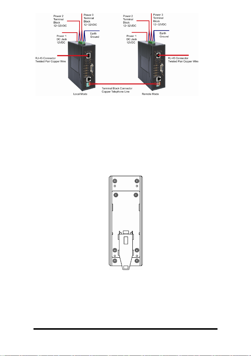
DIN Rail Mounting
• Fix the DIN rail attachment plate to the back panel of the Hardened Managed
Ethernet Extender.
• Installation: Place the Hardened Managed Ethernet Extender on the DIN rail
from above using the slot. Push the front of the Hardened Managed Ethernet
Extender toward the mounting surface until it audibly snaps into place.
• Removal: Pull out the lower edge and then remove the Hardened Managed
Ethernet Extender from the DIN rail.
Manual Documentation Number: EIRM-EXTEND-1412m 7
B&B Electronics Mfg Co Inc – 707 Dayton Rd - PO Box 1040 - Ottawa IL 61350 - Ph 815-433-5100 - Fax 815-433-5104 – www.bb-elec.com
B&B Electronics – Westlink Commercial Park – Oranmore, Galway, Ireland – Ph +353 91-792444 – Fax +353 91-792445 – www.bb-europe.com
Page 14
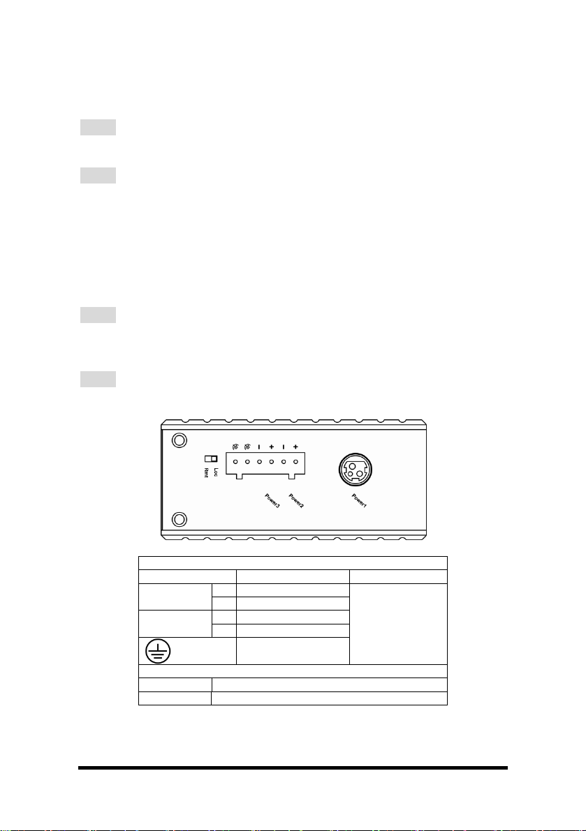
Connecting to Power
Redundant DC Terminal Block Power Inputs or 12VDC DC Jack:
12VDC DC Jack
Step 1: Connect the supplied AC to DC power adapter to the receptacle on
the topside of the Hardened Managed Ethernet Extender.
Step 2: Connect the power cord to the AC to DC power adapter and attach
the plug into a standard AC outlet with the appropriate AC voltage.
Redundant DC Terminal Block Power Inputs
There are two pairs of power inputs can be used to power up this device. You only
need to have one power input connected to run the Hardened Managed Ethernet
Extender.
Step 1: Connect the DC power cord to the plug-able terminal block on the
Hardened Managed Ethernet Extender, and then plug it into a standard DC
outlet.
Step 2: Disconnect the power cord if you want to shut down the Hardened
Managed Ethernet Extender.
Power Input Assignment
Power1 12VDC DC Jack
Power2
Power3
DIP Switch Assignment
Loc The device operates in local mode
Rmt The device operates in remote mode
12-32VDC
Power Ground
12-32VDC
Power Ground
Earth Ground
Terminal Block
8 Manual Documentation Number: EIRM-EXTEND-1412m
B&B Electronics Mfg Co Inc – 707 Dayton Rd - PO Box 1040 - Ottawa IL 61350 - Ph 815-433-5100 - Fax 815-433-5104 – www.bb-elec.com
B&B Electronics – Westlink Commercial Park – Oranmore, Galway, Ireland – Ph +353 91-792444 – Fax +353 91-792445 – www.bb-europe.com
Page 15

Chapter 2 – Web-Based Browser Management
The Hardened Managed Ethernet Extender provides a web-based browser interface
for configuring and managing the Hardened Managed Ethernet Extender. This
interface allows you to access the Hardened Managed Ethernet Extender using a
preferred web browser.
This chapter describes how to configure the Hardened Managed Ethernet Extender
using its web-based browser interface.
Logging in to The Hardened Managed Ethernet Extender
IP Address
In your web browser, specify the IP address of the Hardened Managed Ethernet
Extender. Default IP address is 192.168.1.10.
Password
Enter the factory default password (no password) or user-defined password.
Then select the “Submit” button to log on to the Hardened Managed Ethernet
Extender.
Manual Documentation Number: EIRM-EXTEND-1412m 9
B&B Electronics Mfg Co Inc – 707 Dayton Rd - PO Box 1040 - Ottawa IL 61350 - Ph 815-433-5100 - Fax 815-433-5104 – www.bb-elec.com
B&B Electronics – Westlink Commercial Park – Oranmore, Galway, Ireland – Ph +353 91-792444 – Fax +353 91-792445 – www.bb-europe.com
Page 16

Understanding the Browser Interface
The web browser interface provides groups of point-and-select buttons at the left field
of the screen for configuring and managing the Hardened Managed Ethernet
Extender.
Basic Settings
Network Settings, Server Name Settings, NTP Server Settings
Advanced Settings
Lan Settings, VDSL Settings, SNMP Settings, Link-Fault-Pass-Through Settings, Log
Settings
System Management
Save Configuration, Change Password, Accessible List, Restore Factory Default,
Firmware Upgrade, Reset VDSL, Retrain VDSL
System Monitoring
System Log, VDSL Status
Restart
Restart System
10 Manual Documentation Number: EIRM-EXTEND-1412m
B&B Electronics Mfg Co Inc – 707 Dayton Rd - PO Box 1040 - Ottawa IL 61350 - Ph 815-433-5100 - Fax 815-433-5104 – www.bb-elec.com
B&B Electronics – Westlink Commercial Park – Oranmore, Galway, Ireland – Ph +353 91-792444 – Fax +353 91-792445 – www.bb-europe.com
Page 17

Basic Settings
Network Settings
1. IP configuration: Select “IP configuration” drop-down menu to choose “Static” or
“DHCP” from the “IP configuration” drop-down list for the Hardened Managed
Ethernet Extender to use a static IP or dynamic IP address (the IP address will
be automatically assigned by DHCP server over the network).
2. IP address: Select “IP Address” text box and type a new address to change the
IP Address.
3. Netmask: Select “Netmask” text box and type a new address to change the
Netmask.
4. Gateway: Select the text box and type a new address to change the Gateway.
5. DNS server 1, 2, 3, 4: Select the text box and type a new address to change the
DNS server.
6. Reload: Select “Reload” button to reload previous settings.
7. Submit: Select “Submit” button to apply new settings.
Manual Documentation Number: EIRM-EXTEND-1412m 11
B&B Electronics Mfg Co Inc – 707 Dayton Rd - PO Box 1040 - Ottawa IL 61350 - Ph 815-433-5100 - Fax 815-433-5104 – www.bb-elec.com
B&B Electronics – Westlink Commercial Park – Oranmore, Galway, Ireland – Ph +353 91-792444 – Fax +353 91-792445 – www.bb-europe.com
Page 18

Server Name Settings
1. Server name: Select “Server Name” text box. Type a server name if it is blank,
or replace the current server name with a new one.
2. Reload: Select “Reload” button to reload previous settings.
3. Submit: Select “Submit” button to apply new settings.
12 Manual Documentation Number: EIRM-EXTEND-1412m
B&B Electronics Mfg Co Inc – 707 Dayton Rd - PO Box 1040 - Ottawa IL 61350 - Ph 815-433-5100 - Fax 815-433-5104 – www.bb-elec.com
B&B Electronics – Westlink Commercial Park – Oranmore, Galway, Ireland – Ph +353 91-792444 – Fax +353 91-792445 – www.bb-europe.com
Page 19

NTP Server Settings
NTP Settings:
1. NTP status: Select “NTP status” drop-down menu to select “Enable” or “Disable”
from the “NTP status” drop-down list to enable or disable NTP.
2. NTP Server: Select “NTP Server” text box to enter URL or IP address of NTP
server.
3. Sync Time: Select “Sync Time” button to synchronize system time of Hardened
Managed Ethernet Extender with NTP server.
4. Time Zone: Select “Time Zone” drop-down menu to select a different time zone
from the “Time Zone” drop-down list.
5. Polling Interval (1-10080 min): Select “Polling Interval” text box to enter polling
interval for requesting updated NTP information.
6. Reload: Select “Reload” button to reload previous settings.
7. Submit: Select “Submit” button to apply new settings.
Daylight Saving Settings:
1. Daylight Saving Mode: Select “Daylight Saving Mode” drop-down menu to select
“Enable” or “Disable” from the “Daylight Saving Mode” drop-down list to enable
or disable Daylight Saving settings.
2. Daylight Saving Time Zone: Select “Daylight Saving Time Zone” text box to
enter a name for Daylight Saving Time Zone.
3. Number of Minutes to add (1-1440 min): Select “Number of Minutes to add” text
box to enter the amount of time to constitute your local Daylight Saving offset.
4. Weekday Mode: Choose the week of the month, the day of the week, and the
time that Daylight Saving will start on and end.
5. Date Mode: Choose the month, the day of the month, and the time that Daylight
Saving will start on and end.
6. Reload: Select “Reload” button to reload previous settings.
7. Submit: Select “Submit” button to apply new settings.
Advanced Settings
Manual Documentation Number: EIRM-EXTEND-1412m 13
B&B Electronics Mfg Co Inc – 707 Dayton Rd - PO Box 1040 - Ottawa IL 61350 - Ph 815-433-5100 - Fax 815-433-5104 – www.bb-elec.com
B&B Electronics – Westlink Commercial Park – Oranmore, Galway, Ireland – Ph +353 91-792444 – Fax +353 91-792445 – www.bb-europe.com
Page 20

Lan Settings
1. Auto: Select “Enable” or “Disable” to enable or disable auto negotiation for
Ethernet port of the Hardened Managed Ethernet Extender.
2. Speed: Check “100M” or “10M” to set the speed of Ethernet port to 100Mbps or
10Mbps.
3. Duplex: Check “Full” or “Half” to set the duplex mode of Ethernet port to Full
Duplex or Half Duplex.
4. Reload: Select “Reload” button to reload previous settings.
5. Submit: Select “Submit” button to apply new settings.
VDSL Settings
The Ethernet Extender port of this Hardened Managed Ethernet Extender
can support asymmetric mode (default setting) or symmetric mode for
upstream and downstream transmission.
Downstream
Local mode Remote mode
Upstream
One requirement is to set Fixed Rate for Local mode Hardened Managed
Ethernet Extender. You will not have to set Fixed Rate for Remote mode
Hardened Managed Ethernet Extender. Local mode Hardened Managed
Ethernet Extender will dominate Fixed Rate for this pair. When Hardened
Managed Ethernet Extender is set to Local mode, the speed LEDs will
follow downstream speed. And when Hardened Managed Ethernet
Extender is set to Remote mode, the speed LEDs will follow upstream
speed.
14 Manual Documentation Number: EIRM-EXTEND-1412m
B&B Electronics Mfg Co Inc – 707 Dayton Rd - PO Box 1040 - Ottawa IL 61350 - Ph 815-433-5100 - Fax 815-433-5104 – www.bb-elec.com
B&B Electronics – Westlink Commercial Park – Oranmore, Galway, Ireland – Ph +353 91-792444 – Fax +353 91-792445 – www.bb-europe.com
Page 21

Enable Asymmetric Mode:
1. Asymmetric Mode: Check “Enable” to enable asymmetric mode for Ethernet
Extender port of the Hardened Managed Ethernet Extender.
2. Fixed Rate: Select “Fixed Rate” drop-down menu to disable fixed speed rate or
select a fixed speed rate for Ethernet Extender port from the “Fixed Rate” dropdown list.
Fixed Rate: bps
Disable
59M /
31M
52M /
24M
47M /
14M
42M / 8M
35M / 6M
28M / 5M
25M / 2M
22M / 1M
14M / 1M
1M / 1M
3. Reload: Select “Reload” button to reload previous settings.
4. Submit: Select “Submit” button to apply new settings.
Disable Asymmetric Mode:
1. Asymmetric Mode: Check “Disable” to disable asymmetric mode for Ethernet
Extender port of the Hardened Managed Ethernet Extender.
2. Max. Speed: Select “Max. Speed” drop-down menu to select a maximum speed
for Ethernet Extender port from the “Max. Speed” drop-down list.
Manual Documentation Number: EIRM-EXTEND-1412m 15
B&B Electronics Mfg Co Inc – 707 Dayton Rd - PO Box 1040 - Ottawa IL 61350 - Ph 815-433-5100 - Fax 815-433-5104 – www.bb-elec.com
B&B Electronics – Westlink Commercial Park – Oranmore, Galway, Ireland – Ph +353 91-792444 – Fax +353 91-792445 – www.bb-europe.com
Page 22

Max. Speed: bps
50M
40M
30M
25M
20M
15M
10M
5M
3M
1M
3. Fixed Rate: Select “Fixed Rate” drop-down menu to disable fixed speed rate or
select a fixed speed rate for Ethernet Extender port from the “Fixed Rate” dropdown list.
Fixed Rate: bps
Disable
50M
40M
30M
25M
20M
15M
10M
5M
3M
1M
4. Reload: Select “Reload” button to reload previous settings.
5. Submit: Select “Submit” button to apply new settings.
16 Manual Documentation Number: EIRM-EXTEND-1412m
B&B Electronics Mfg Co Inc – 707 Dayton Rd - PO Box 1040 - Ottawa IL 61350 - Ph 815-433-5100 - Fax 815-433-5104 – www.bb-elec.com
B&B Electronics – Westlink Commercial Park – Oranmore, Galway, Ireland – Ph +353 91-792444 – Fax +353 91-792445 – www.bb-europe.com
Page 23

SNMP Settings
1. Get community: Select the “Get community” textbox and specify a get
community name.
2. Set community: Select the “Set Community” textbox and specify a set
community name.
3. sysContact: Select the “sysContact” textbox and specify a new contact for
SNMP.
4. sysLocation: Select the “sysLocation” textbox and specify a new location for
SNMP.
5. sysDescr: Select the “sysDescr” textbox and specify a new description for
SNMP.
6. IP of remote SNMP trap receiver: For each “IP of remote SNMP trap receiver”,
Select the “IP of remote SNMP trap receiver” textbox and specify an IP address
of remote SNMP trap receiver.
7. Reload: Select “Reload” button to reload previous settings.
8. Submit: Select “Submit” button to apply new settings.
Manual Documentation Number: EIRM-EXTEND-1412m 17
B&B Electronics Mfg Co Inc – 707 Dayton Rd - PO Box 1040 - Ottawa IL 61350 - Ph 815-433-5100 - Fax 815-433-5104 – www.bb-elec.com
B&B Electronics – Westlink Commercial Park – Oranmore, Galway, Ireland – Ph +353 91-792444 – Fax +353 91-792445 – www.bb-europe.com
Page 24

Link-Fault-Pass-Through Settings
1. Link-Fault-Pass-Through: Check “Enable” or “Disable” to enable or disable linkfault-pass-through for the Hardened Managed Ethernet Extender.
2. Reload: Select “Reload” button to reload previous settings.
3. Submit: Select “Submit” button to apply new settings.
Log Settings
1. Event Log: Check or uncheck “Enable” to enable or disable Event Log Setting
for the Hardened Managed Ethernet Extender.
2. Log File Transfer: Select the “Log File Transfer” textbox and specify the IP
address of TFTP server.
3. Submit: Select “Submit” button to apply new settings.
4. Transfer: Select “Transfer” button to transfer log file to TFTP server.
System Management
18 Manual Documentation Number: EIRM-EXTEND-1412m
B&B Electronics Mfg Co Inc – 707 Dayton Rd - PO Box 1040 - Ottawa IL 61350 - Ph 815-433-5100 - Fax 815-433-5104 – www.bb-elec.com
B&B Electronics – Westlink Commercial Park – Oranmore, Galway, Ireland – Ph +353 91-792444 – Fax +353 91-792445 – www.bb-europe.com
Page 25
Save Configuration
1. Submit: Select “Submit” button to save configuration.
Change Password
1. Old password: Select “Old password” text box and type in the old password.
2. New password: Select “New password” text box and type in the new password.
3. Confirm password: Select “Confirm password” text box. Type the same
password in “New password” text box again to verify it.
4. Submit: Select “Submit” button to apply new settings.
Manual Documentation Number: EIRM-EXTEND-1412m 19
B&B Electronics Mfg Co Inc – 707 Dayton Rd - PO Box 1040 - Ottawa IL 61350 - Ph 815-433-5100 - Fax 815-433-5104 – www.bb-elec.com
B&B Electronics – Westlink Commercial Park – Oranmore, Galway, Ireland – Ph +353 91-792444 – Fax +353 91-792445 – www.bb-europe.com
Page 26

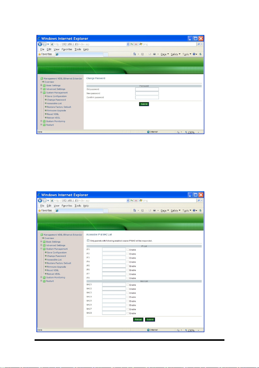
Accessible List
1. Only packets with following enabled source IP/MAC will be responded: Check
this option to enable the following accessible source IP/MAC list. Uncheck this
option will allow all source IP/MAC’s connection request.
2. IP1 ~ 8: Select “IP1 ~ 8” text box and specify IP addresses that can access to
the Ethernet port on the Hardened Managed Ethernet Extender. Check “Enable”
option to enable the IP addresses.
3. MAC1 ~ 8: Select “MAC1 ~ 8” text box and specify MAC addresses that can
access to the Ethernet port on the Hardened Managed Ethernet Extender.
Check “Enable” option to enable the MAC addresses.
4. Reload: Select “Reload” button to reload previous settings.
5. Submit: Select “Submit” button to apply new settings.
Restore Factory Default
1. Restore Password Only: Check this option to restore the factory default
password.
2. Restore factory defaults (all): Check this option to restore the Hardened
Managed Ethernet Extender to the factory default values.
3. Restore factory defaults except networking settings: Check this option to restore
the Hardened Managed Ethernet Extender to the factory default values but keep
networking settings of the Hardened Managed Ethernet Extender.
4. Submit: Select “Submit” button to apply new settings.
20 Manual Documentation Number: EIRM-EXTEND-1412m
B&B Electronics Mfg Co Inc – 707 Dayton Rd - PO Box 1040 - Ottawa IL 61350 - Ph 815-433-5100 - Fax 815-433-5104 – www.bb-elec.com
B&B Electronics – Westlink Commercial Park – Oranmore, Galway, Ireland – Ph +353 91-792444 – Fax +353 91-792445 – www.bb-europe.com
Page 27

Firmware Upgrade
1. Filename: Select “Filename” text box and type the name of the file that you
intend to upgrade it to the Hardened Managed Ethernet Extender.
2. TFTP server IP: Select the “TFTP server IP” textbox and specify the IP address
of TFTP server.
3. Submit: Select “Submit” button to apply new settings.
Reset VDSL
1. Submit: Select “Submit” button to re-negotiate Ethernet Extender port.
Manual Documentation Number: EIRM-EXTEND-1412m 21
B&B Electronics Mfg Co Inc – 707 Dayton Rd - PO Box 1040 - Ottawa IL 61350 - Ph 815-433-5100 - Fax 815-433-5104 – www.bb-elec.com
B&B Electronics – Westlink Commercial Park – Oranmore, Galway, Ireland – Ph +353 91-792444 – Fax +353 91-792445 – www.bb-europe.com
Page 28

Retrain VDSL
1. Submit: Select “Submit” button to attempt a higher link speed for the Ethernet
Extender port. For example, the current link speed of Ethernet Extender port is
at 25Mbps. The user can select the “Submit” button which will allow the Ethernet
Extender port attempt a link at 30Mbps.
22 Manual Documentation Number: EIRM-EXTEND-1412m
B&B Electronics Mfg Co Inc – 707 Dayton Rd - PO Box 1040 - Ottawa IL 61350 - Ph 815-433-5100 - Fax 815-433-5104 – www.bb-elec.com
B&B Electronics – Westlink Commercial Park – Oranmore, Galway, Ireland – Ph +353 91-792444 – Fax +353 91-792445 – www.bb-europe.com
Page 29

System Monitoring
System Log
1. Reload: Select the “Reload” button to reload the system log of the Hardened
Managed Ethernet Extender.
2. Reset / Clear: Select “Reset / Clear” button to reset and clean the system log of
the Hardened Managed Ethernet Extender.
Manual Documentation Number: EIRM-EXTEND-1412m 23
B&B Electronics Mfg Co Inc – 707 Dayton Rd - PO Box 1040 - Ottawa IL 61350 - Ph 815-433-5100 - Fax 815-433-5104 – www.bb-elec.com
B&B Electronics – Westlink Commercial Park – Oranmore, Galway, Ireland – Ph +353 91-792444 – Fax +353 91-792445 – www.bb-europe.com
Page 30

VDSL Status
1. Reload: Select the “Reload” button to reload the VDSL status of the Hardened
Managed Ethernet Extender.
2. Reset / Clear: Select “Reset / Clear” button to reset and clean the VDSL status
of the Hardened Managed Ethernet Extender.
Restart
Restart System
1. Submit: Select “Submit” button to restart the Hardened Managed Ethernet
Extender.
24 Manual Documentation Number: EIRM-EXTEND-1412m
B&B Electronics Mfg Co Inc – 707 Dayton Rd - PO Box 1040 - Ottawa IL 61350 - Ph 815-433-5100 - Fax 815-433-5104 – www.bb-elec.com
B&B Electronics – Westlink Commercial Park – Oranmore, Galway, Ireland – Ph +353 91-792444 – Fax +353 91-792445 – www.bb-europe.com
Page 31

Chapter 3 – Command Line Console Management
The Hardened Managed Ethernet Extender provides a command line console
interface for configuration purposes. The Hardened Managed Ethernet Extender can
be configured either locally through its RS-232 port or remotely via a Telnet session.
For the later, you must specify an IP address for the switch first.
This chapter describes how to configure the Hardened Managed Ethernet Extender
using its console by Commend Line.
Connect the DB9 straight cable to the DCE female RS-232 serial port of the device to
the DTE male RS-232 serial port of the terminal or computer running the terminal
emulation application.
Direct access to the administration console is achieved by directly connecting a
terminal or a PC equipped with a terminal-emulation program (such as
HyperTerminal) to the Hardened Managed Ethernet Extender console port.
When using the management method, configure the terminal-emulation program to
use the following parameters (you can change these settings after login):
[Default parameters]
115,200bps
8 data bits
No parity
1 stop bit
At the login: prompt just type in “root” and press <Enter>.
At the Password: prompt just press <Enter> to logon to the Hardened Managed
Ethernet Extender.
Manual Documentation Number: EIRM-EXTEND-1412m 25
B&B Electronics Mfg Co Inc – 707 Dayton Rd - PO Box 1040 - Ottawa IL 61350 - Ph 815-433-5100 - Fax 815-433-5104 – www.bb-elec.com
B&B Electronics – Westlink Commercial Park – Oranmore, Galway, Ireland – Ph +353 91-792444 – Fax +353 91-792445 – www.bb-europe.com
Page 32

The basic commands in the Command Line Interface (CLI) are listed in the following
table.
System Management
Command Command Description
sys uptime Display system uptime.
sys date Display system date and time.
sys date –s MMDDhhmmYYYY.ss
MM: Month
DD: Day
hh: Hour
mm: Minute
YYYY: Year
ss: Second
sys hostname Display system name.
sys hostname hostname Set system name.
sys snmp Display SNMP settings.
sys snmp disp Display SNMP settings.
sys snmp getcommunity Display SNMP GetRequest
sys snmp getcommunity
CommunityName
sys snmp setcommunity Display SNMP SetRequest
sys snmp setcommunity
CommunityName
sys snmp syslocation Display location of the device.
sys snmp syslocation location Set location of the device.
sys snmp syscontact Display contact person for the
sys snmp syscontact contact Set contact person for the device.
sys snmp sysdescr Display description of the device.
sys snmp sysdescr description Set description for the device.
sys snmp trapdest add IP Add destination IP address of
sys snmp trapdest delete IP Delete destination IP address of
sys passwd Set new password.
sys actl on Set access control ON to the
sys actl off Set access control OFF to the
sys actl disp Display access control settings.
Set system date and time.
community.
Set SNMP GetRequest
community.
community.
Set SNMP SetRequest
community.
device.
SNMP trap.
SNMP trap.
device.
device.
26 Manual Documentation Number: EIRM-EXTEND-1412m
B&B Electronics Mfg Co Inc – 707 Dayton Rd - PO Box 1040 - Ottawa IL 61350 - Ph 815-433-5100 - Fax 815-433-5104 – www.bb-elec.com
B&B Electronics – Westlink Commercial Park – Oranmore, Galway, Ireland – Ph +353 91-792444 – Fax +353 91-792445 – www.bb-europe.com
Page 33

sys actl add mac MAC Add MAC address to accessible
list.
sys actl add ip IP Add IP address to accessible list.
sys actl del mac index Remove index_th MAC address
from accessible list.
sys actl del ip index Remove index_th IP address from
accessible list.
sys actl del mac all Remove all MAC addresses from
accessible list.
sys actl del ip all Remove all IP addresses from
accessible list.
sys actl enable mac index Enable index_th MAC address
from accessible list.
sys actl enable ip index Enable index_th IP address from
accessible list.
sys actl disable mac index Disable index_th MAC address
from accessible list.
sys actl disable ip index Disable index_th IP address from
accessible list.
sys reboot Reboot system.
sys reset level1 Restore default password.
sys reset level2 Restore factory default.
sys reset level3 Restore factory default except
network settings.
sys ntp Display NTP settings.
sys ntp on Set NTP ON.
sys ntp off Set NTP OFF.
sys ntp server IP Set IP address of NTP time server
to the device.
sys ntp zone time_zone
Set NTP time zone to the device.
time_zone: +12.0 ~ -12.0
sys summer-time off Set summer-time OFF.
sys summer-time time_zone weekday
week day month hh:mm week day
Set summer-time ON in the
weekday mode.
month hh:mm offset
sys summer-time time_zone date date
month hh:mm date month hh:mm
Set summer-time ON in the date
mode.
offset
sys log Display log settings.
sys log on Set log ON.
sys log off Set log OFF.
sys log reset Clear content of log.
sys log send IP Send the log file to TFTP server.
sys log disp Display log settings.
Manual Documentation Number: EIRM-EXTEND-1412m 27
B&B Electronics Mfg Co Inc – 707 Dayton Rd - PO Box 1040 - Ottawa IL 61350 - Ph 815-433-5100 - Fax 815-433-5104 – www.bb-elec.com
B&B Electronics – Westlink Commercial Park – Oranmore, Galway, Ireland – Ph +353 91-792444 – Fax +353 91-792445 – www.bb-europe.com
Page 34

sys upgrade IP filename Upgrade system with new
firmware from a TFTP server.
sys lfpt Display Link Fault Pass Through
settings.
sys lfpt on Set Link Fault Pass Through ON.
sys lfpt off Set Link Fault Pass Through
OFF.
The basic commands in the Command Line Interface (CLI) are listed in the following
table.
28 Manual Documentation Number: EIRM-EXTEND-1412m
B&B Electronics Mfg Co Inc – 707 Dayton Rd - PO Box 1040 - Ottawa IL 61350 - Ph 815-433-5100 - Fax 815-433-5104 – www.bb-elec.com
B&B Electronics – Westlink Commercial Park – Oranmore, Galway, Ireland – Ph +353 91-792444 – Fax +353 91-792445 – www.bb-europe.com
Page 35

System Management
Command Command Description
sys uptime Display system uptime.
sys date Display system date and time.
sys date –s MMDDhhmmYYYY.ss
MM: Month
DD: Day
hh: Hour
mm: Minute
YYYY: Year
ss: Second
sys hostname Display system name.
sys hostname hostname Set system name.
sys snmp Display SNMP settings.
sys snmp disp Display SNMP settings.
sys snmp getcommunity Display SNMP GetRequest
sys snmp getcommunity
CommunityName
sys snmp setcommunity Display SNMP SetRequest
sys snmp setcommunity
CommunityName
sys snmp syslocation Display location of the device.
sys snmp syslocation location Set location of the device.
sys snmp syscontact Display contact person for the
sys snmp syscontact contact Set contact person for the device.
sys snmp sysdescr Display description of the device.
sys snmp sysdescr description Set description for the device.
sys snmp trapdest add IP Add destination IP address of
sys snmp trapdest delete IP Delete destination IP address of
sys passwd Set new password.
sys actl on Set access control ON to the
sys actl off Set access control OFF to the
sys actl disp Display access control settings.
sys actl add mac MAC Add MAC address to accessible
sys actl add ip IP Add IP address to accessible list.
Set system date and time.
community.
Set SNMP GetRequest
community.
community.
Set SNMP SetRequest
community.
device.
SNMP trap.
SNMP trap.
device.
device.
list.
Manual Documentation Number: EIRM-EXTEND-1412m 29
B&B Electronics Mfg Co Inc – 707 Dayton Rd - PO Box 1040 - Ottawa IL 61350 - Ph 815-433-5100 - Fax 815-433-5104 – www.bb-elec.com
B&B Electronics – Westlink Commercial Park – Oranmore, Galway, Ireland – Ph +353 91-792444 – Fax +353 91-792445 – www.bb-europe.com
Page 36

sys actl del mac index Remove index_th MAC address
from accessible list.
sys actl del ip index Remove index_th IP address from
accessible list.
sys actl del mac all Remove all MAC addresses from
accessible list.
sys actl del ip all Remove all IP addresses from
accessible list.
sys actl enable mac index Enable index_th MAC address
from accessible list.
sys actl enable ip index Enable index_th IP address from
accessible list.
sys actl disable mac index Disable index_th MAC address
from accessible list.
sys actl disable ip index Disable index_th IP address from
accessible list.
sys reboot Reboot system.
sys reset level1 Restore default password.
sys reset level2 Restore factory default.
sys reset level3 Restore factory default except
network settings.
sys ntp Display NTP settings.
sys ntp on Set NTP ON.
sys ntp off Set NTP OFF.
sys ntp server IP Set IP address of NTP time server
to the device.
sys ntp zone time_zone
Set NTP time zone to the device.
time_zone: +12.0 ~ -12.0
sys summer-time off Set summer-time OFF.
sys summer-time time_zone weekday
week day month hh:mm week day
Set summer-time ON in the
weekday mode.
month hh:mm offset
sys summer-time time_zone date date
month hh:mm date month hh:mm
Set summer-time ON in the date
mode.
offset
sys log Display log settings.
sys log on Set log ON.
sys log off Set log OFF.
sys log reset Clear content of log.
sys log send IP Send the log file to TFTP server.
sys log disp Display log settings.
sys upgrade IP filename Upgrade system with new
firmware from a TFTP server.
sys lfpt Display Link Fault Pass Through
30 Manual Documentation Number: EIRM-EXTEND-1412m
B&B Electronics Mfg Co Inc – 707 Dayton Rd - PO Box 1040 - Ottawa IL 61350 - Ph 815-433-5100 - Fax 815-433-5104 – www.bb-elec.com
B&B Electronics – Westlink Commercial Park – Oranmore, Galway, Ireland – Ph +353 91-792444 – Fax +353 91-792445 – www.bb-europe.com
Page 37

settings.
sys lfpt on Set Link Fault Pass Through ON.
sys lfpt off Set Link Fault Pass Through
OFF.
Manual Documentation Number: EIRM-EXTEND-1412m 31
B&B Electronics Mfg Co Inc – 707 Dayton Rd - PO Box 1040 - Ottawa IL 61350 - Ph 815-433-5100 - Fax 815-433-5104 – www.bb-elec.com
B&B Electronics – Westlink Commercial Park – Oranmore, Galway, Ireland – Ph +353 91-792444 – Fax +353 91-792445 – www.bb-europe.com
Page 38

Ethernet Extender Management
Command Command Description
vdsl status Display link performance of
Ethernet Extender port.
vdsl counter Display statistic counter of
Ethernet Extender port.
vdsl disp Display settings of Ethernet
Extender port.
vdsl reset chip Reset chip of Ethernet Extender
port.
vdsl reset counter Reset counter of Ethernet
Extender port.
vdsl au Display auto upgrade settings of
Ethernet Extender port.
vdsl au disp Display auto upgrade settings of
Ethernet Extender port.
vdsl au level number
number: 0 ~ 9
vdsl fixedrate level_number
level_number: -1 ~ 9
vdsl retrain Upgrade speed of Ethernet
vdsl asym-mode on Asymmetric mode is enabled.
vdsl asym-mode off Asymmetric mode is disabled.
Set auto upgrade level for
Ethernet Extender port.
Set fixed rate level (-1 ~ 9) for
Ethernet Extender port, -1 to
represent disable.
Extender port.
32 Manual Documentation Number: EIRM-EXTEND-1412m
B&B Electronics Mfg Co Inc – 707 Dayton Rd - PO Box 1040 - Ottawa IL 61350 - Ph 815-433-5100 - Fax 815-433-5104 – www.bb-elec.com
B&B Electronics – Westlink Commercial Park – Oranmore, Galway, Ireland – Ph +353 91-792444 – Fax +353 91-792445 – www.bb-europe.com
Page 39

Network Management
Command Command Description
net ifconfig Display network configuration.
net ifconfig disp Display network configuration.
net ifconfig ip IP
IP: IP address of the device
net ifconfig netmask IP
IP: netmask address for the device
net ifconfig up Activate network interface.
net ifconfig down Shutdown network interface.
net ping IP
IP: IP address
net arp Display ARP table.
net gateway Display gateway settings.
net gateway disp Display gateway settings.
net gateway add IP
IP: gateway address
net gateway del IP
IP: gateway address
net dns Display DNS settings.
net dns disp Display DNS settings.
net dns add IP
IP: DNS address
net dns del IP
IP: DNS address
net dhcp Display DHCP settings.
net dhcp disp Display DHCP settings.
net dhcp on Set the device to get IP address
net dhcp off Set IP address to the device
net dhcp renew Set the device to get new IP
net an Display auto negotiation settings.
net an disp Display auto negotiation settings.
net an on Set auto negotiation ON.
net an off Set auto negotiation OFF.
net an speed speed
speed: 10 or 100
net an duplex duplex
duplex: half or full
net disp Display all settings.
Set IP address to the device.
Set netmask address to the device.
Send ICMP ECHO_REQUEST to
network hosts.
Add gateway address to the
device.
Remove gateway address from
the device.
Add DNS address to the device.
Remove DNS address from the
device.
from DHCP server.
manually.
address from DHCP server.
Set LAN speed.
Set LAN duplex mode.
Manual Documentation Number: EIRM-EXTEND-1412m 33
B&B Electronics Mfg Co Inc – 707 Dayton Rd - PO Box 1040 - Ottawa IL 61350 - Ph 815-433-5100 - Fax 815-433-5104 – www.bb-elec.com
B&B Electronics – Westlink Commercial Park – Oranmore, Galway, Ireland – Ph +353 91-792444 – Fax +353 91-792445 – www.bb-europe.com
Page 40

NET-SNMP
Object Name Type Value Setting Description
Model
modeName String(R/W) String
serialNumber String(R/W) String
versionHW String(R/W) String
versionSW String(R/W) String
mconf
sysContact String(R/W) String
sysDescr String(R/W) String
sysLocation String(R/W) String
machineName String(R/W) String
Dhcp String(R/W) “1” or “0”
Ntp String(R/W) “1” or “0”
ntpServer String(R/W) IP or String
timezone String(R/W) String Time Zone
gmtOffset String(R/W) -12.0~+12.0 GMT Offset
ntpPollingInterval String(R/W) 1~10080
ac(Access Control)
Checked String(R/W) “1” or “0”
acIP0~acIP7
Checked String(R/W) “1” or “0”
IP IP format IP address
acMAC0~acMAC7
Checked String(R/W) “1” or “0”
MAC MAC format(R/W) MAC address
communityGet String(R/W) String
communitySet String(R/W) String
serverTrap
serverTrap0 String(R/W) IP address
serverTrap1 String(R/W) IP address
serverTrap2 String(R/W) IP address
serverTrap3 String(R/W) IP address
Log String(R/W) “1” or “0”
EthernetConf
MAC MAC format(R/W) MAC address
IP IP format(R/W) IP address
Netmask IP format(R/W) IP address
Gateway IP format(R/W) IP address
DNS
DNS0 IP format(R/W) IP address
DNS1 IP format(R/W) IP address
DNS2 IP format(R/W) IP address
DNS3 IP format(R/W) IP address
AN String(R/W) “1” or “0” Auto Negotiation
Setspeed String(R/W) “10” or “100”
Setduplex String(R/W) “H” or “F”
EthernetStatus
Speed String(R) LAN speed
ModeStatus String(R)
FlowControl String(R)
VDSLConf
Opmode String(R)
UpgradeLevel Integer(R/W) “0” or “1” Max. upgrade
10 = 10M
100 = 100M
H = Half
F = Full
D = Duplex
H = Half-Duplex
Flow Control
status
C = CO
P = CPE
R = RO
34 Manual Documentation Number: EIRM-EXTEND-1412m
B&B Electronics Mfg Co Inc – 707 Dayton Rd - PO Box 1040 - Ottawa IL 61350 - Ph 815-433-5100 - Fax 815-433-5104 – www.bb-elec.com
B&B Electronics – Westlink Commercial Park – Oranmore, Galway, Ireland – Ph +353 91-792444 – Fax +353 91-792445 – www.bb-europe.com
Page 41

level
ResetVDSL Integer(R/W) “0” or “1”
ResetVDSLCounter Integer(R/W) “0” or “1”
VDSLStatus
LinkPerformance
TimeConnect Integer(R)
SnrBand1 Integer(R)
SnrBand2 Integer(R)
ERRS Integer(R)
FailCnt Integer(R)
LFrLosCnt Integer(R)
SOTO Integer(R)
SORO Integer(R)
BCAST Integer(R)
RXPAUS Integer(R)
TXPAUS Integer(R)
TXBCNT Integer(R)
RXBCNT Integer(R)
LinkFaultPassThrough
LFPT String(R/W) “1” or “0”
Reset VDSL
chip
Reset VDSL
counter
SNR of 1st
Upstream Band
SNR of 2st
Upstream Band
Uncorrectable
code words
Disconnection
Counter
Loss of Frame
Counter
Bytes
transmitted OK
counter
Bytes received
OK counter
Broadcast frames
received counter
Reception pause
packets counter
Transmission
pause packets
counter
Number of
transmitted
frames
Number of
received frames
Manual Documentation Number: EIRM-EXTEND-1412m 35
B&B Electronics Mfg Co Inc – 707 Dayton Rd - PO Box 1040 - Ottawa IL 61350 - Ph 815-433-5100 - Fax 815-433-5104 – www.bb-elec.com
B&B Electronics – Westlink Commercial Park – Oranmore, Galway, Ireland – Ph +353 91-792444 – Fax +353 91-792445 – www.bb-europe.com
Page 42

Specifications
Applicable Standards
Fixed Ports 1 x 10/100Mbps Ethernet port with RJ-45 connector
Speed
10Base-T
100Base-TX
Ethernet Extender
Switching Method Store-and-Forward
Forwarding rate 14,880/148,810pps for 10/100Mbps
Cable
10Base-T
100Base-TX
Ethernet Extender
LED Indicators Per Unit (3 LEDs)- Power1, Power2, Power3
Dimensions 50mm (W) × 110mm (D) x 135mm (H)
Weight 0.8Kg (1.76lbs.)
Power
Operating Voltage &
Max.
Current Consumption
Power Consumption 6W Max.
Operating Temperature
Storage Temperature -40°C ~ 85°C (-40°F ~ 185°F)
Humidity 5 ~ 95%, non-condensing
Safety UL508, EN60950-1, IEC60950-1
IEEE802.3 10Base-T, IEEE802.3u 100BaseTX,
Ethernet over VDSL
1 x Ethernet Extender port with RJ-11 and Terminal
Block connectors
10/20Mbps for half/full-duplex
100/200Mbps for half/full-duplex
1, 3, 5, 10, 15, 20, 25, 30, 40, 50Mbps
2-pair UTP/STP Cat. 3, 4, 5 up to 100m
2-pair UTP/STP Cat. 5 up to 100m
Telephone wires
Per Port-
RJ-45 (2 LEDs): Link/ACT, FDX
RJ-11, Terminal Block (9 LEDs): Remote,
Local, Error, Link, 1, 2, 3, 4, 5
(1.97” (W) x 4.33” (D) x 5.31” (H))
Terminal Block: 12-32VDC
DC Jack: 12VDC, External AC/DC required
0.5A @ 12VDC, 0.25A @ 24VDC
-40°C ~ 75°C (-40℉ ~ 167℉)
Tested for functional operation @
-40°C ~ 85°C (-40℉ ~ 185℉)
UL508 Industrial Control Equipment certified
Maximum Surrounding Air Temperature @
75 (167℉)
36 Manual Documentation Number: EIRM-EXTEND-1412m
B&B Electronics Mfg Co Inc – 707 Dayton Rd - PO Box 1040 - Ottawa IL 61350 - Ph 815-433-5100 - Fax 815-433-5104 – www.bb-elec.com
B&B Electronics – Westlink Commercial Park – Oranmore, Galway, Ireland – Ph +353 91-792444 – Fax +353 91-792445 – www.bb-europe.com
Page 43

EMI FCC Part 15, Class A
VCCI, Class A
EN61000-6-4: EN55022, EN61000-3-2,
EN61000-3-3
EMS
EN61000-6-2:
EN61000-4-2 (ESD Standard)
EN61000-4-3 (Radiated RFI Standards)
EN61000-4-4 (Burst Standards)
EN61000-4-5 (Surge Standards)
EN61000-4-6 (Induced RFI Standards)
EN61000-4-8 (Magnetic Field Standards)
Environmental Test
Compliance
NEMA TS1/2 Environmental requirements for traffic control equipment
IEC60068-2-6 Fc (Vibration Resistance)
IEC60068-2-27 Ea (Shock)
IEC60068-2-32 Ed (Free Fall)
Manual Documentation Number: EIRM-EXTEND-1412m 37
B&B Electronics Mfg Co Inc – 707 Dayton Rd - PO Box 1040 - Ottawa IL 61350 - Ph 815-433-5100 - Fax 815-433-5104 – www.bb-elec.com
B&B Electronics – Westlink Commercial Park – Oranmore, Galway, Ireland – Ph +353 91-792444 – Fax +353 91-792445 – www.bb-europe.com
Page 44

NET-SNMP
Object Name Type Value Setting Description
Model
modeName String(R/W) String
serialNumber String(R/W) String
versionHW String(R/W) String
versionSW String(R/W) String
mconf
sysContact String(R/W) String
sysDescr String(R/W) String
sysLocation String(R/W) String
machineName String(R/W) String
Dhcp String(R/W) “1” or “0”
Ntp String(R/W) “1” or “0”
ntpServer String(R/W) IP or String
timezone String(R/W) String Time Zone
gmtOffset String(R/W) -12.0~+12.0 GMT Offset
ntpPollingInterval String(R/W) 1~10080
ac(Access Control)
Checked String(R/W) “1” or “0”
acIP0~acIP7
Checked String(R/W) “1” or “0”
IP IP format IP address
acMAC0~acMAC7
Checked String(R/W) “1” or “0”
MAC MAC format(R/W) MAC address
communityGet String(R/W) String
communitySet String(R/W) String
serverTrap
serverTrap0 String(R/W) IP address
serverTrap1 String(R/W) IP address
serverTrap2 String(R/W) IP address
serverTrap3 String(R/W) IP address
Log String(R/W) “1” or “0”
EthernetConf
MAC MAC format(R/W) MAC address
IP IP format(R/W) IP address
Netmask IP format(R/W) IP address
Gateway IP format(R/W) IP address
DNS
DNS0 IP format(R/W) IP address
DNS1 IP format(R/W) IP address
DNS2 IP format(R/W) IP address
DNS3 IP format(R/W) IP address
AN String(R/W) “1” or “0” Auto Negotiation
Setspeed String(R/W) “10” or “100”
Setduplex String(R/W) “H” or “F”
EthernetStatus
Speed String(R) LAN speed
ModeStatus String(R)
FlowControl String(R)
VDSLConf
Opmode String(R)
10 = 10M
100 = 100M
H = Half
F = Full
D = Duplex
H = Half-Duplex
Flow Control
status
C = CO
P = CPE
R = RO
38 Manual Documentation Number: EIRM-EXTEND-1412m
B&B Electronics Mfg Co Inc – 707 Dayton Rd - PO Box 1040 - Ottawa IL 61350 - Ph 815-433-5100 - Fax 815-433-5104 – www.bb-elec.com
B&B Electronics – Westlink Commercial Park – Oranmore, Galway, Ireland – Ph +353 91-792444 – Fax +353 91-792445 – www.bb-europe.com
Page 45

UpgradeLevel Integer(R/W) “0” or “1”
ResetVDSL Integer(R/W) “0” or “1”
ResetVDSLCounter Integer(R/W) “0” or “1”
VDSLStatus
LinkPerformance
TimeConnect Integer(R)
SnrBand1 Integer(R)
SnrBand2 Integer(R)
ERRS Integer(R)
FailCnt Integer(R)
LFrLosCnt Integer(R)
SOTO Integer(R)
SORO Integer(R)
BCAST Integer(R)
RXPAUS Integer(R)
TXPAUS Integer(R)
TXBCNT Integer(R)
RXBCNT Integer(R)
LinkFaultPassThrough
LFPT String(R/W) “1” or “0”
Max. upgrade
level
Reset VDSL
chip
Reset VDSL
counter
SNR of 1st
Upstream Band
SNR of 2st
Upstream Band
Uncorrectable
code words
Disconnection
Counter
Loss of Frame
Counter
Bytes
transmitted OK
counter
Bytes received
OK counter
Broadcast frames
received counter
Reception pause
packets counter
Transmission
pause packets
counter
Number of
transmitted
frames
Number of
received frames
Manual Documentation Number: EIRM-EXTEND-1412m 39
B&B Electronics Mfg Co Inc – 707 Dayton Rd - PO Box 1040 - Ottawa IL 61350 - Ph 815-433-5100 - Fax 815-433-5104 – www.bb-elec.com
B&B Electronics – Westlink Commercial Park – Oranmore, Galway, Ireland – Ph +353 91-792444 – Fax +353 91-792445 – www.bb-europe.com
Page 46

40 Manual Documentation Number: EIRM-EXTEND-1412m
B&B Electronics Mfg Co Inc – 707 Dayton Rd - PO Box 1040 - Ottawa IL 61350 - Ph 815-433-5100 - Fax 815-433-5104 – www.bb-elec.com
B&B Electronics – Westlink Commercial Park – Oranmore, Galway, Ireland – Ph +353 91-792444 – Fax +353 91-792445 – www.bb-europe.com
 Loading...