

Page 1
Manual
Elinx EIRHP305-T
5 Ports10/100 with 4 PoE Ports
Unmanaged Din Rail Ethernet Switch
Page 2

EIRHP305-T
Documentation Number: EIRHP305-T-1712m
International Headquarters:
707 Dayton Road
Ottawa, IL 61350 USA
Phone (815) 433-5100
Website: www.bb-elec.com
Sales e-mail: orders@bb-elec.com
Technical Support: support@bb.elec.com –
European Headquarters
B&B Electronics
Westlink Commercial Park
Oranmore, Co. Galway, Ireland
Phone +353 91-792444
Website: www.bb-europe.com
Sales e-mail: sales@bb-europe.com
Technical Support: support@bb-europe.com
Original – April 2011
©2011 No part of this public ation may be r eproduced or t ransmitted in any form or by any means,
electronic or mechanical, including photography, recording, or any information stora ge and retrieval
system without written consent. Infor mation in this manual is subject to change without notice, and does
not represent a commitment on the part.
B&B Electro nics Manufact uring shall not be liable for incidental or conseque ntial damages resulting fr om
the furnishing, perform ance, or use of this manual. A ll brand names used in this m anual are the
registered t rademarks of their respective owners. The use of trademarks or oth er designations in this
publication is for reference pur poses only and does not constitute an endorsement by the trademark
holder.
Page 3

Table of Contents
OVERVIEW ................................................................... 1
Features ....................................................................................................... 1
HARDWARE DESCRIPTION ........................................ 3
Dimensions .................................................................................................. 3
Front Panel ................................................................................................. 4
Top View ..................................................................................................... 4
LED Indicators ........................................................................................... 5
RJ45 ............................................................................................................. 6
Cabling ........................................................................................................ 8
Wiring the Power Inputs ........................................................................... 8
MOUNTING INSTALLATION ....................................... 9
DIN-Rail Mounting .................................................................................... 9
Hanging the Industrial Switch ................................................................ 10
Wall-Mount Plate Mounting ................................................................... 11
Hardware Installation Diagram .............................................................. 12
Troubleshooting ........................................................................................ 13
Technical Specification ............................................................................ 14
i
Page 4

Page 5

Overview
B&B Electronics PoE Ethernet switch, 5 port 10/100TX with 4 offering
High-Power (25W) PoE ports. The Industrial Switch is a cost-effective
solution whic h mee ts t he high reliability requirements demanded by
industrial applications. The Ethernet switch supports wide temperature 40°C - 75°C environments. The PoE feature meets IEEE 802.3af prestandard, which supports 25 watts @ 48VDC on each PoE po rt.
Features
• System Interface/Performance
o RJ-45 ports support Auto MDI/MDI-X Function
o Embedded 4-ports PoE
o Store-and-Forward Switching Architecture
o Back-plane (Switching Fabric): 1 . 0Gbps
o 2K MAC Address Table
• Power Input
o DC 48V Redundant Power Input
• Operating Temperature
o Wide Operating Temp: -40°C -75°C
• Case/Installation
o IP-30 Protection
o Installation in a Pollution Deg r e e 2 environment
o DIN Rail and Wall Mount Design
• Provides EFT protection 3,000 VDC for power line
• Supports 6,000 VDC Ethernet ESD protection
Manual Documentation Number: EIRHP305-T-1712m 1
B&B Electronics Mfg Co Inc – 707 Dayton Rd - PO Box 1040 - Ottawa IL 61350 - P h 815-433-5100 - Fax 815-433-5104 – www.bb-elec.com
B&B Electronics – Westlink Commercial Park – Oranmore, Galway, Ireland – Ph +353 91-792444 – Fax +353 91-792445 – www.bb-europe.com
Page 6

Package Contents
• 5 port 10/100TX with 4 Port High-Power (25W) PoE Indust rial
Switch (with DIN -Rail Bracket)
• User manual
• Removable Terminal Block
• Wall-mount Kit (2 wall-mount bracket with screws)
2 Manual Documentation Number: EIRHP305-T-1712m
B&B Electronics Mfg Co Inc – 707 Dayton Rd - PO Box 1040 - Ottawa IL 61350 - P h 815-433-5100 - Fax 815-433-5104 – www.bb-elec.com
B&B Electronics – Westlink Commercial Park – Oranmore, Galway, Ireland – Ph +353 91-792444 – Fax +353 9 1-792445 – www.bb-europe.com
Page 7

Hardware Description
The following information is an introd uction to the PoE Industr ial Et hernet
Switch dimensions, port, cabling information, and wiring installation.
Dimensions
5 port 10/100T(X) with 4 High-Power (25W) PoE ports Industrial Switch
dimensions (W x D x H) is 48.60mm x 95mm x 140mm, the detail
dimensions as Figure-1
Figure-1: Mechanical Dimensions
Manual Documentation Number: EIRHP305-T-1712m 3
B&B Electronics Mfg Co Inc – 707 Dayton Rd - PO Box 1040 - Ottawa IL 61350 - P h 815-433-5100 - Fax 815-433-5104 – www.bb-elec.com
B&B Electronics – Westlink Commercial Park – Oranmore, Galway, Ireland – Ph +353 91-792444 – Fax +353 91-792445 – www.bb-europe.com
Page 8

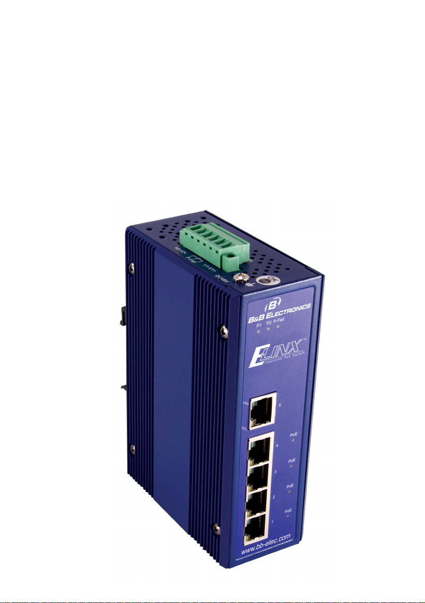
Front Panel
The Front Panel of the 5 port 10/100TX with 4 Port High-Power (25W)
PoE Industrial Switch is shown below Figure-2
Figure-2: Front Panel of the Switch
Top View
The top view displays one terminal block connector, which allows wiring
of two DC power inputs a nd a Relay circuit contact. Please refer to Figure-
3 for furt h er information.
Figure-3: Top View of the Switch
4 Manual Documentation Number: EIRHP305-T-1712m
B&B Electronics Mfg Co Inc – 707 Dayton Rd - PO Box 1040 - Ottawa IL 61350 - P h 815-433-5100 - Fax 815-433-5104 – www.bb-elec.com
B&B Electronics – Westlink Commercial Park – Oranmore, Galway, Ireland – Ph +353 91-792444 – Fax +353 9 1-792445 – www.bb-europe.com
Page 9

LED Indicators
The diagnostic LEDs located on the front panel of the industrial switch
provide real-time information of system and operation status. Table-1
provides the description of the LEDs status and their definitions.
Wiring the Power Inputs
Table-1: LED Indication De finition
Manual Documentation Number: EIRHP305-T-1712m 5
B&B Electronics Mfg Co Inc – 707 Dayton Rd - PO Box 1040 - Ottawa IL 61350 - P h 815-433-5100 - Fax 815-433-5104 – www.bb-elec.com
B&B Electronics – Westlink Commercial Park – Oranmore, Galway, Ireland – Ph +353 91-792444 – Fax +353 91-792445 – www.bb-europe.com
Page 10

RJ45
The RJ45 copper ports support auto MDI/MDIX operation. This feature
allows network connections to co mputers, servers, or ot her switches using
straight-through or crossover cables (See Figure below). Straight-through
cable connections: pins 1, 2, 3 and 6, at one end of the cable, are connected
straight-through to pins 1, 2, 3 and 6 at the other end of the cable. The table
below shows the 10BASE-T/100BASE-TX MDI and MDI-X port pin outs.
6 Manual Documentation Number: EIRHP305-T-1712m
B&B Electronics Mfg Co Inc – 707 Dayton Rd - PO Box 1040 - Ottawa IL 61350 - P h 815-433-5100 - Fax 815-433-5104 – www.bb-elec.com
B&B Electronics – Westlink Commercial Park – Oranmore, Galway, Ireland – Ph +353 91-792444 – Fax +353 9 1-792445 – www.bb-europe.com
Page 11

Manual Documentation Number: EIRHP305-T-1712m 7
B&B Electronics Mfg Co Inc – 707 Dayton Rd - PO Box 1040 - Ottawa IL 61350 - P h 815-433-5100 - Fax 815-433-5104 – www.bb-elec.com
B&B Electronics – Westlink Commercial Park – Oranmore, Galway, Ireland – Ph +353 91-792444 – Fax +353 91-792445 – www.bb-europe.com
Page 12

V- V+
V- V+
Cabling
Use unshielded twisted-pair (UTP) or shielded twisted-pair (STP) cable for
RJ-45 connect ions: 100Ω Category 3, 4 or 5 cable for 10Mbps
connections, 100Ω Category 5 cable for 100Mbps, or 100Ω Category
5e/above cable for 1000Mbps connections.
The cable between the switch and the link partner ( switch, hub,
workstation, etc.) must be less than 10 0 meters (328 ft.) long.
Wiring the Power Inputs
Note:
1. Terminal blocks are rated for 12-24 AWG wire
2. Use copper conductors, 60/75
o
C. Tighten to 5 lb in.
8 Manual Documentation Number: EIRHP305-T-1712m
B&B Electronics Mfg Co Inc – 707 Dayton Rd - PO Box 1040 - Ottawa IL 61350 - P h 815-433-5100 - Fax 815-433-5104 – www.bb-elec.com
B&B Electronics – Westlink Commercial Park – Oranmore, Galway, Ireland – Ph +353 91-792444 – Fax +353 9 1-792445 – www.bb-europe.com
Page 13

Rear Panel of the
Mounting Installation
DIN-Rail Mounting
Assembling the DIN-Rail Clip
switch
DIN-rail clip
Manual Documentation Number: EIRHP305-T-1712m 9
B&B Electronics Mfg Co Inc – 707 Dayton Rd - PO Box 1040 - Ottawa IL 61350 - P h 815-433-5100 - Fax 815-433-5104 – www.bb-elec.com
B&B Electronics – Westlink Commercial Park – Oranmore, Galway, Ireland – Ph +353 91-792444 – Fax +353 91-792445 – www.bb-europe.com
Page 14

Hanging the Industrial Switch
First, position the din-rail clip of the switch directly in front of the DIN rail.
Make sure the top of the clip hooks over the top of the DIN rail.
Push the unit downward.
Check the DIN-Rail clip is tightly fixed on the DIN rail.
To remove the industrial switch from the track, reverse the steps above.
10 Manual Documentation Number: EIRHP305-T-1712m
B&B Electronics Mfg Co Inc – 707 Dayton Rd - PO Box 1040 - Ottawa IL 61350 - P h 815-433-5100 - Fax 815-433-5104 – www.bb-elec.com
B&B Electronics – Westlink Commercial Park – Oranmore, Galway, Ireland – Ph +353 91-792444 – Fax +353 9 1-792445 – www.bb-europe.com
Page 15

Wall-Mount Plate Mounting
1. When using the wall mount plates the din-rail clip can be
removed.
2. Place the wall-mount plates on the rear panel of the industrial
switch and fasten the screws .
Wall-Mount Bracket Dimens ions
Manual Documentation Number: EIRHP305-T-1712m 11
B&B Electronics Mfg Co Inc – 707 Dayton Rd - PO Box 1040 - Ottawa IL 61350 - P h 815-433-5100 - Fax 815-433-5104 – www.bb-elec.com
B&B Electronics – Westlink Commercial Park – Oranmore, Galway, Ireland – Ph +353 91-792444 – Fax +353 91-792445 – www.bb-europe.com
Page 16

Hardware Installation Diagram
12 Manual Documentation Number: EIRHP305-T-1712m
B&B Electronics Mfg Co Inc – 707 Dayton Rd - PO Box 1040 - Ottawa IL 61350 - P h 815-433-5100 - Fax 815-433-5104 – www.bb-elec.com
B&B Electronics – Westlink Commercial Park – Oranmore, Galway, Ireland – Ph +353 91-792444 – Fax +353 9 1-792445 – www.bb-europe.com
Page 17

Troubleshooting
• Do not use the power adapter with DC output higher than the power
rating of the device.
• Select the proper UTP/STP cable to const ruct your network. Use
unshielded twisted-pair (UTP) or shielded twisted-pair (STP) cable
for RJ-45 connections: 100Ω Category 3, 4 or 5 cable for 10Mbps
connections, 100Ω Category 5 cable for 100Mbps, or 100Ω
Category 5e/above cable for 1000Mbps connections. Insure the
length of any twisted-pair connection does not exceed 100 meters
(328 feet).
• Diagnosing LED Indicators: The Switch can be easily monitored
through panel LED’s. The LED’s will provide an easy way of
detecting power or communication problems.
• During loss or no communications verify the Industrial switch LED
indicators are dis playing normal opera ting status. Next perform the
ping test to confirm connection and status of device connections on
the networ k.
Manual Documentation Number: EIRHP305-T-1712m 13
B&B Electronics Mfg Co Inc – 707 Dayton Rd - PO Box 1040 - Ottawa IL 61350 - P h 815-433-5100 - Fax 815-433-5104 – www.bb-elec.com
B&B Electronics – Westlink Commercial Park – Oranmore, Galway, Ireland – Ph +353 91-792444 – Fax +353 91-792445 – www.bb-europe.com
Page 18

Technical Specification
The 5 port 10/100TX with 4 port High-Power (25W) PoE Industrial Switch
technical specifications is shown as below.
14 Manual Documentation Number: EIRHP305-T-1712m
B&B Electronics Mfg Co Inc – 707 Dayton Rd - PO Box 1040 - Ottawa IL 61350 - P h 815-433-5100 - Fax 815-433-5104 – www.bb-elec.com
B&B Electronics – Westlink Commercial Park – Oranmore, Galway, Ireland – Ph +353 91-792444 – Fax +353 9 1-792445 – www.bb-europe.com
Page 19

Manual Documentation Number: EIRHP305-T-1712m 15
B&B Electronics Mfg Co Inc – 707 Dayton Rd - PO Box 1040 - Ottawa IL 61350 - P h 815-433-5100 - Fax 815-433-5104 – www.bb-elec.com
B&B Electronics – Westlink Commercial Park – Oranmore, Galway, Ireland – Ph +353 91-792444 – Fax +353 91-792445 – www.bb-europe.com
 Loading...