

Page 1
Quick Start Guide
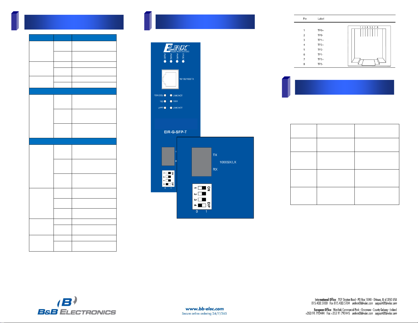
ELinx EIR-G-SFP-T
10/100/1000Base-TX to Gigabit
SFP Media Converter
1
Items Included
2
Hardware Installation
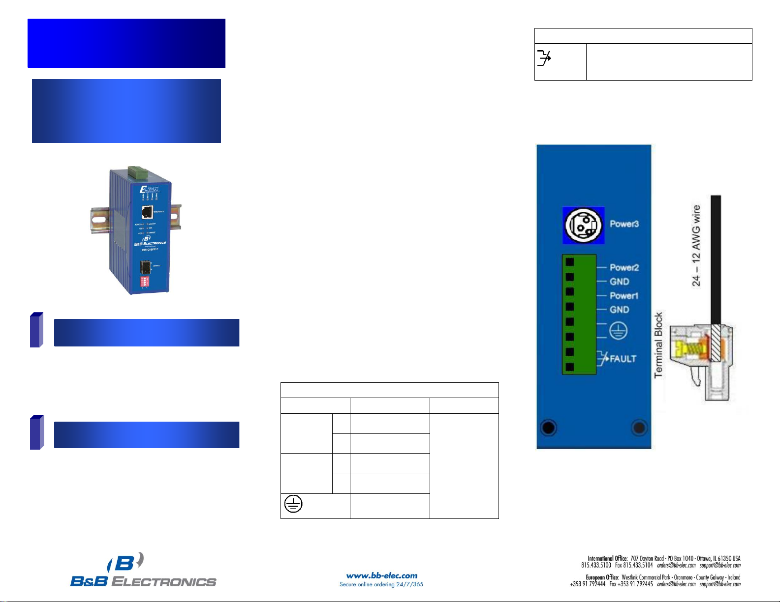
Power Input Assignment
Power3
12VDC
DC Jack
Power2
+
12-48VDC
Terminal Block
-
Power Ground
Power1
+
12-48VDC
-
Power Ground
Earth Ground
Relay Alarm Assignment
FAULT
1. The relay contact opens if Power1 or
Power2 fail.
2. The relay contact closes when Power1
and Power2 are both on.
o Gigabit Media Converter
o This Quick Start Guide
Note: Required but not included. Power supply, 12 – 48
VDC 10.6 watts. A gigabit 1000Base-SX/LX SFP
module.
1. This is a DIN rail mountable hardened media converter
and can be located in environments with temperatures
ranging from -40 to 75° C. The relative humidity should
be less than 95%, non-condensing.
2. Mount the converter on standard DIN rail by hooking
the top rear of the media converter onto the top edge
of the DIN rail. Using a small flat head screwdriver,
pull down on the spring-loaded tab on the bottom of
the unit and push the unit back against the rail.
Release the spring-loaded tab locking the media
converter to the bottom edge of the DIN rail. Reverse
these steps to remove. Also, can be panel mounted
with optional kit (EIRPMKT).
3. Insert 1000Base-SX/LX module into SFP socket.
Accepts 1000Base multi-mode or single-mode fiber
SFP modules.
4. Insert RJ-45 Ethernet line into 1000Base-T port first and
then connect the fiber port. The copper port auto
negotiates speed and supports auto MDI/MDIX for uplink
purposes.
5. Provide DC power to the unit between 12 – 48 volts.
While only one power source is required to power up
the media converter, using two sources provides
redundancy for mission critical applications. The
removable terminal block accepts 12 – 24 AWG wire.
Be sure polarity matches diagram next to the terminal
block. Terminals labeled Power are positive while
GND is negative.
6. The terminal labeled Fault is connected to a dry
contact and is rated 1 amp at 24VDC. The dry
contact is normally closed when power is connected
to both Power1 and Power2. When power fails on
either Power1 or Power2 the contact will open
signaling power failure. Power3 has no effect.
7. Power3 is available for use with optional 12VDC AC
to DC power adapter (PS12VDC3P).
EIR-G-SFP-T 4612qsg
Page 2
EIR-G-SFP-T 4612qsg
3
LED Chart
4
Ports
5
DIP Switch Settings
LEDs
State
Indication
FAULT
Steady
Power1, Power2, or
ports fail
Off
Power and ports
functioning normally
Power1
Power2
Power3
Steady
Power on
Off
Power off
LFPT
Steady
LFPT function enabled
Off
LFPT function disabled
1000Base-SX/LX
LINK/ACT
Steady
A valid network
connection established
for SFP port
Flashing
Transmitting or receiving
data
ACT stands for Activity
Off
No valid network
connection established
for SFP port
10/100/1000Base-TX
LINK/ACT
Steady
A valid network
connection established
for copper port
Flashing
Transmitting or receiving
data
ACT stands for Activity
Off
No valid network
connection established
for copper port
FDX/COL
Steady
Connected in full duplex
mode
Flashing
Collision occurred
COL stands for Collision
Off
Connected in half duplex
mode
1000
Steady
Connected at 1000Mbps
Off
Not connected at
1000Mbps
100
Steady
Connected at 100Mbps
Off
Connected at 10Mbps
(100 & 1000 both Off)
DIP Switch
No.
0 (OFF)
1 (ON)
1
Disable LFPT (default)
Enable LFPT
2
Disable link down
alarm for copper port
(default)
Enable link down alarm for
copper port
3
Disable link down
alarm for SFP socket
port (default)
Enable link down alarm for
SFP socket port
Force Full Duplex
mode for SFP socket
port
Enable Duplex autonegotiation for SFP socket
port (default)
The copper port is 10/100/1000Base-TX and will auto
negotiate a connection starting at gigabit speed.
High quality Category 5e cable or better should be used.
1000BASE-T requires all four pairs to be present and is far
less tolerant of poorly installed wiring than 100BASE-TX
systems. A 1000Base-SX/LX SFP module socket for Gigabit
optic expansion is located above DIP switch.
This device is plug_and_play; however, the following DIP
switch selections are available.
There are four pins on the DIP switch for port settings as
shown in the table below.
Link-Fault-Pass-Through (DIP Switch 1)
The default setting is link-fault-pass-through OFF. If not
enabled and one side of the link fails, the other side continues
transmitting packets, and waits for a response that never
comes. When ON, LFPT will force the link to shut down as
soon as it notices that the other link has failed. This gives the
application software a chance to react to the situation.
Link Down Alarm (DIP Switch 2 & 3) By default, the link
down alarms are disabled for both copper and fiber.
Duplex Mode (DIP Switch 4) The default setting is autonegotiation ON. You may force full duplex mode when set in
OFF position.
 Loading...