

Page 1
1
Items Included
2
Hardware Installation
3
Front Panel & LED Chart
Quick Start Guide
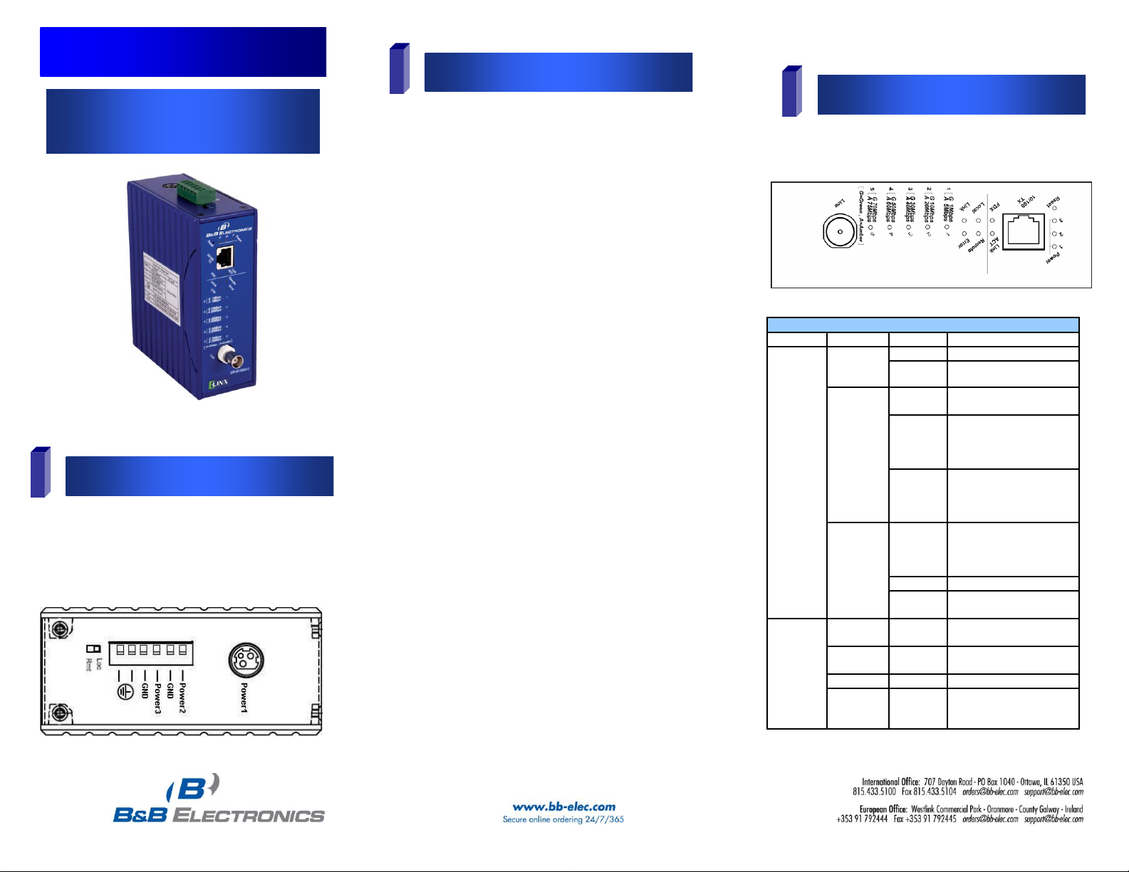
EIR-EXTEND-C
Ethernet Coaxial Extender
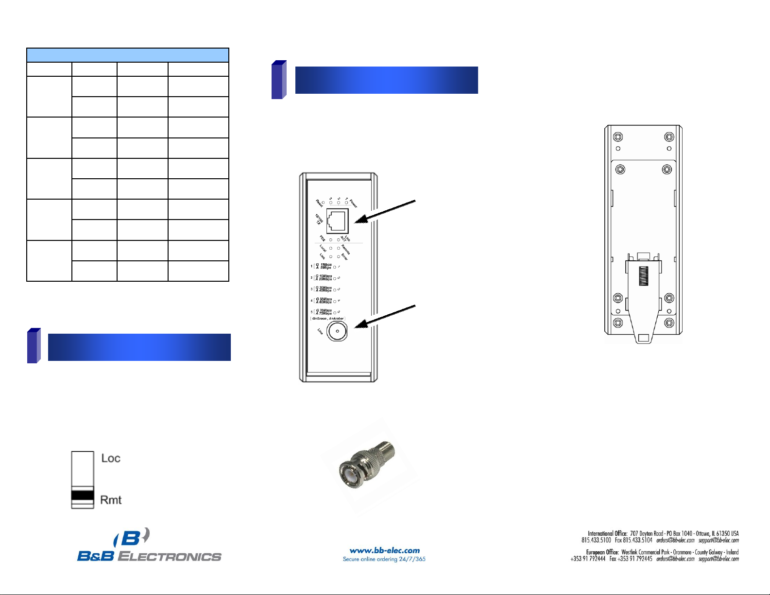
Front Panel LED’s (Ethernet and Line Connections)
Port
LEDs
Status
Description
Ethernet
(RJ-45)
Power1
Power2
Power3
Steady
Power on
Off
Power off
Link/ACT
Steady
Valid Ethernet
connection established
Flashing
Transmitting or
receiving Ethernet
data (ACT stands for
ACTIVITY)
Off
No valid Ethernet
connection nor
transmitting/receiving
Ethernet data
FDX
Steady
Ethernet connection in
full duplex mode
(FDX stands for FULL-
DUPLEX)
Flashing
Collision occurred
Off
Ethernet connection in
half-duplex mode
Line
(BNC)
Remote
Steady
Operating in remote
mode
Local
Steady
Operating in local
mode
Error
Steady
Error occurred
Link
Steady
A valid connection
established between
local & remote
1. The extender is DIN rail mountable and can be
located in environments with temperatures ranging
from -40 to 75°C. Relative humidity should be
between 5% to 95%, non-condensing.
2. Mount the extender on standard DIN rail by hooking
the top rear of the extender on to the top edge of the
DIN rail. As the unit is pressed into the DIN rail, the
spring-loaded bottom tab should snap on, securing
the bottom. To remove extender from DIN rail, use a
small flathead screw driver, pull down on the spring
loaded tab on the bottom of the extender while pulling
bottom outward. The extender can also be panel
mounted using the optional panel mount kit
EIRPMKT.
3. Provide DC power to the unit between 12 – 48 volts.
While only one power source is required to power up
the Ethernet Extender, using two sources provides
redundancy for mission critical applications. The
removable terminal block accepts 14 – 24 AWG wire.
Use copper conductors only, 60/75℃, 14-24 AWG
torque value 4.5 lb-in.
4. Be sure polarity matches diagram next to the
terminal block. Terminals labeled Power are
positive while GND is negative. An optional power
port labeled Power1 is available with use of
12VDC AC to DC power adapter (PS12VDC3P).
5. Set the DIP switch located on the top of the Ethernet
Extender to Loc (Local) or Rmt (Remote). Ethernet
Extenders work in pairs and must have one unit set as
Loc, the other as Rmt.
6. Connect the Ethernet cable to the RJ-45 port on the
front of Ethernet Extender.
7. Connect the coaxial cable to the BNC port on the front
of the Ethernet Extender. Opposite end connects with
paired Ethernet Extender located elsewhere. Coax
cable must be terminated with male BNC or F
connectors. BNC to F-Type adaptor required for F
style connector (included).
o Ethernet Coaxial Extender
o This Quick Start Guide
o BNC to F-Type Adaptor
Note: Extender requires 12 – 48 VDC, 6.8 watts, power
supply (not included).
The LED indicators give you instant feedback on status of
the Ethernet Extender. Both port speeds are auto sensed.
The EIR-EXTEND-C provides one Ethernet port over
existing coaxial cable.
EIR-EXTEND-C-0812qsg
Page 2
4
DIP Switch Settings
5
Ports
Top LEDs (BNC Line Connections)
LEDs
Status
Speed
Distance
1
Green
1~ 5Mbps
up to 2600M
Amber
6~10Mbps
up to 2400M
2
Green
11~16Mbps
up to 2000M
Amber
17~20Mbps
up to 1800M
3
Green
21~29Mbps
up to 1600M
Amber
30~43Mbps
up to 1400M
4
Green
44~54Mbps
up to 1200M
Amber
55~63Mbps
up to 1000M
5
Green
64~74Mbps
up to 600M
Amber
75~85Mbps
up to 200M
The Ethernet Extender has two ports, a RJ-45
10/100Base TX port and the Ethernet Extender port.
Existing coaxial cable can be used. If coaxial cable
requires termination, use BNC or F-connectors. F style
will require BNC to F-Type adaptor. When BNC extender
ports on the units are connected, Lnk LED should be lit.
Ethernet Extender mode settings are made very simple by
means of a switch at the top of the Ethernet Extender. One
device must be set to local (Loc) and the other to
remote (Rmt) before devices are connected.
It makes no difference which unit is designated local and
remote as long as they are not both set the same.
BNC to F-Type Adaptor
Note: Distance and speed may vary. The above table
represents the maximum performance which can be
expected under ideal conditions.
Spring loaded DIN rail clip on
back of Ethernet Extender
BNC port
RJ-45 10/100Bas TX port
EIR-EXTEND-C-0812qsg
 Loading...