

Page 1
1
2
345
Pos
Status
Description
1
OFF
Disable port 1 Alarm
ON
Enable port 1 Alarm
(If port 1 link fails, the fault LED will light)
2
OFF
Disable port 2 Alarm
ON
Enable port 2 Alarm
(If port 2 link fails, the fault LED will light)
3
OFF
Disable port 3 Alarm
ON
Enable port 3 Alarm
(If port 3 link fails, the fault LED will light)
4
OFF
Disable port 4 Alarm
ON
Enable port 4 Alarm
(If port 4 link fails, the fault LED will light)
5
OFF
Disable port 5 Alarm
ON
Enable port 5 Alarm
(If port 5 link fails, the fault LED will light)
6
OFF
Disable port 6 Alarm
ON
Enable port 6 Alarm
(If port 6 link fails, the fault LED will light)
7
OFF
Disable port 7 Alarm
ON
Enable port 7 Alarm.
(If port 7 link fails, the fault LED will light)
8
OFF
Disable port 8 Alarm
ON
Enable port 8 Alarm
(If port 8 link fails, the fault LED will light)
9
OFF
Disable the ring master function.
ON
Enable the switch as the ring master
in the redundant ring group.
LED
Status
Meaning
Power
Green
The Switch is powered on
Off
The Switch is powered off
Power 1
Green
Power Source 1 is available
Off
Power Source 1 is unavailable
Power 2
Green
Power Source 1 is available
Off
Power Source 2 is unavailable
Fault
Yellow
Power Source failure or Port Failure
Off
Normal Operation
R.M.
Green
Ring Master (Master of a redundant ring)
Off
The switch is not a Ring Master
LNK/ACT
Ports 7 & 8
Green
The port is linked
Blinking
The port is receiving or transmitting packets
Off
No device attached
FDX/COL
Ports 7 & 8
Yellow
Full Duplex Mode
Blinking
Data Collision
Off
Half Duplex Mode
10/100 Ports
Green
Yellow
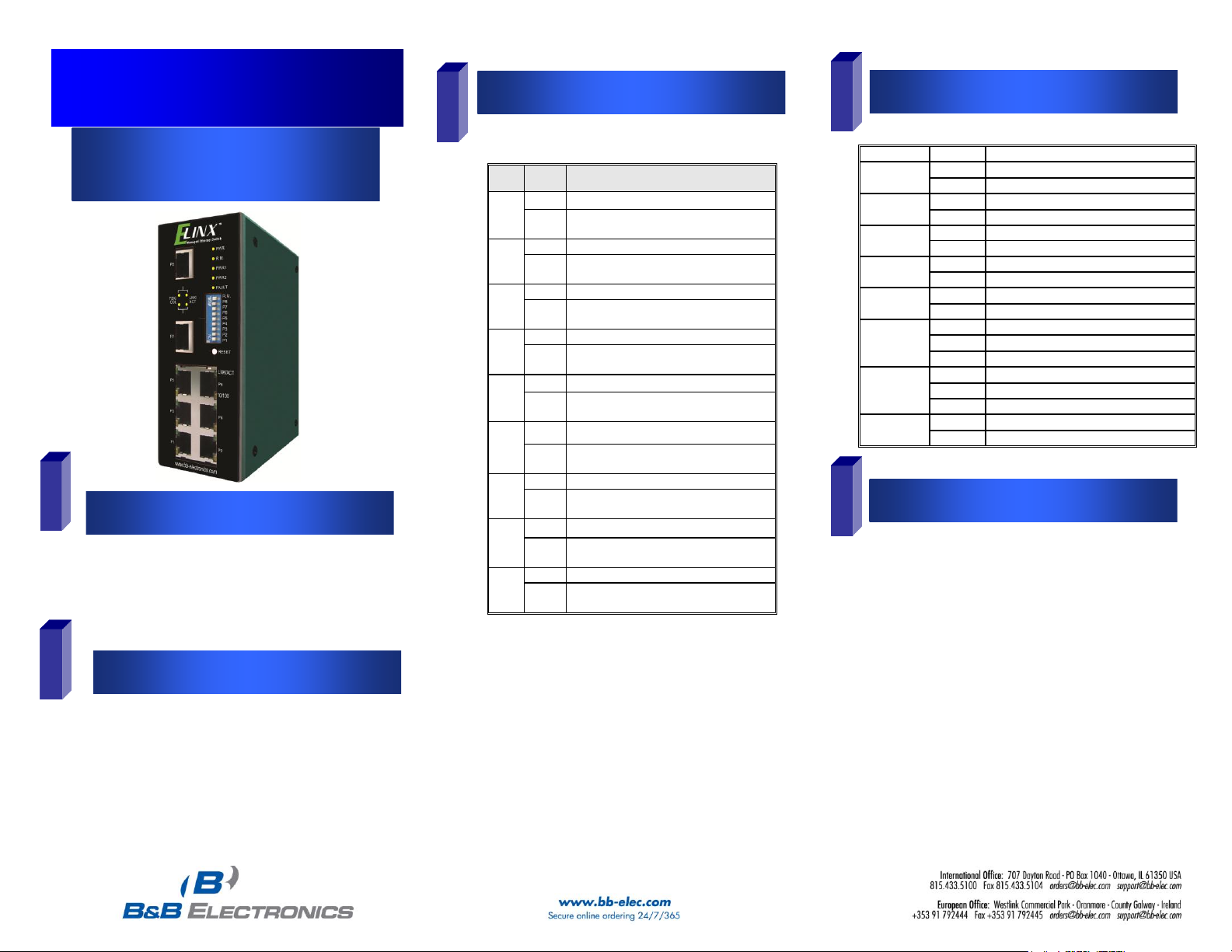
Quick Start Guide
Elinx Managed Ethernet Switch
EIR508 Series
Items Included
Default Settings
DIP Switch Settings
LED Chart
Hardware Installation
o Ethernet Switch
o CD with Support Manual
o This Quick Start Guide
o Panel Mount Bracket
o IP Address: 192.168.16.1
o Subnet Mask: 255.255.255.0
o Gateway: 192.168.16.254
o User Name: root, Password: root
EIR508 Series-1713qsg
o Record the switch’s MAC Address in the space
provided. The MAC Address is printed on the product
label. Provide the MAC Address to your Network
Administrator. The Network Administrator should
provide an IP Address, Subnet Mask, and Gateway.
o Select a mounting location and install with the attached
DIN rail clip or included panel mount kit.
o Connect power to the switch
o 12 to 48 VDC
o Redundant DC input is available with fault
contacts.
Page 2
678
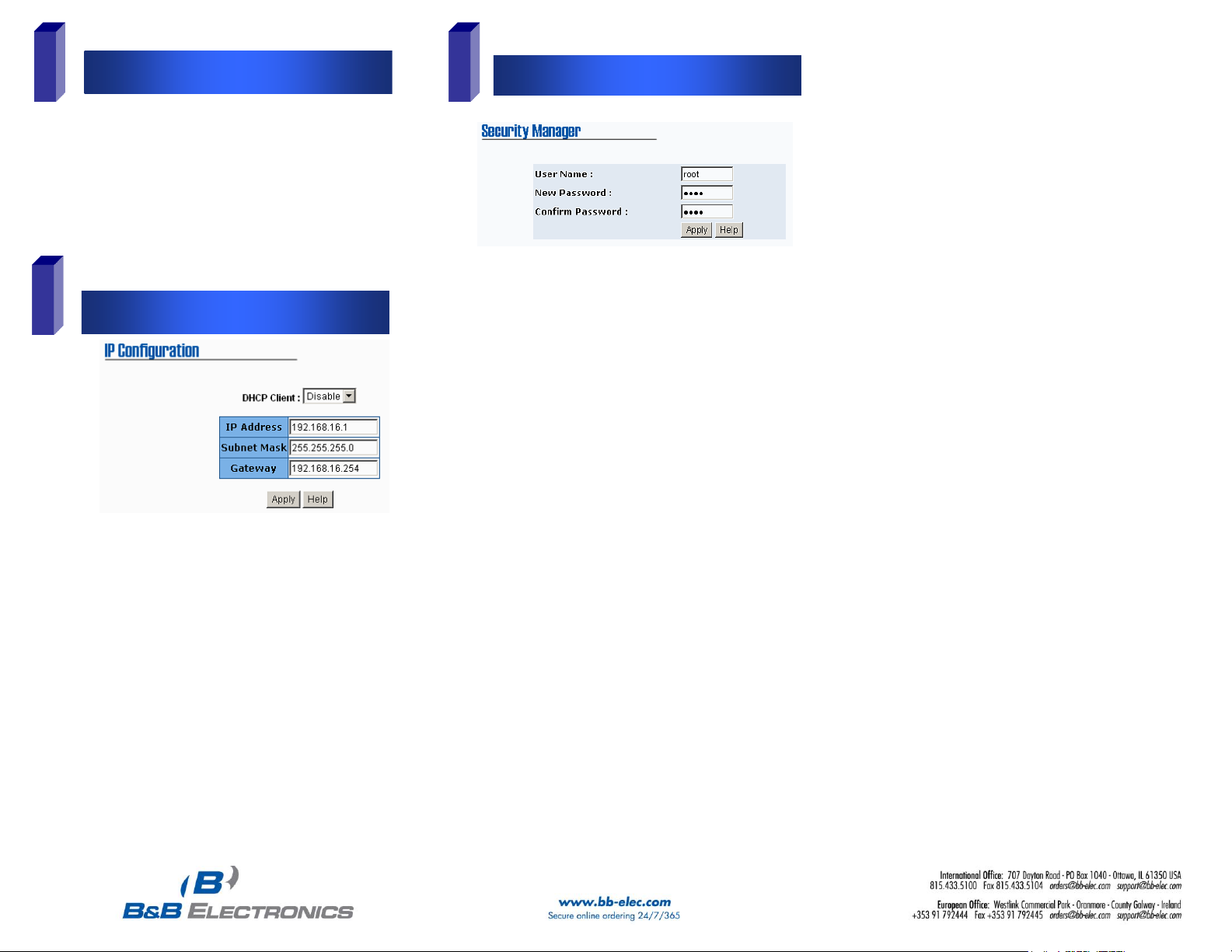
Log into the Switch
IP Configuration
User Name and Password
o Connect a stand alone PC to a port on the switch.
Change the PC’s network IP Address to allow it to
connect to the switch (ex: 192.168.16.2). Use the
default subnet mask and gateway.
o Launch the PC’s web browser and navigate to the
switch by typing the switch’s IP address in the browser
address window.
o Navigate the web page by clicking on the links located
on the top of the web page.
o Click on the IP Configuration link at the top of the web
page.
o Enter the IP Address, Subnet Mask, and Gateway
provided by your Network Administrator.
o Save changes
o Disconnect the stand alone PC and connect the switch
to the Network.
o Inform your Network Administrator that the IP Address
has been changed.
o NOTE: The User Manual contains instructions for
assigning the IP Address from a DHCP Server.
o This step should be accomplished by your Network
Administrator.
o Log onto the switch from a network PC.
o Click on the Security Manager link on the top of the web
page.
o Enter the new User Name and Password. Record this
information in the space provided below. File this
document for future reference.
o Click the Apply button.
o Click the “Save Configuration” link at the top of the web
page.
USER NAME: ______________________________________
PASSWORD:_______________________________________
MAC ADDRESS: ____________________________________
IP ADDRESS:_______________________________________
Basic Configuration is complete. A
comprehensive Manual is contained on the CD
ROM. Refer to this manual to configure the
advanced features of this switch.
EIR508 Series-1713qsg
 Loading...