


EII
E
R
R
Uss
U
4
1
4
1
err
e
8--
8
M
M
2
2
a
a
S
S
n
n
F
F
u
u
P--
P
all
a
T
T
Manual Documentation Number EIR418-2SFP-T – 0109m
www.bb-elec.com
www.bb-europe.com

EEIIRR441188--22SSFFPP--TT
DDooccuummeennttaattiioonn NNuummbbeerr:: EEIIRR441188--22SSFFPP--TT-- 00110099mm
UUssiinngg ddoommeessttiicc a
International Headquarters
International Headquarters
B&B Electronics Mfg. Co. Inc.
Ottawa, IL 61350 USA
Phone (815) 433-5100 -- General Fax (815) 433-5105
Website: www.bb-elec.com
European Headquarters
anndd iimmppoorrtteedd ppaarrttss bbyy
707 Dayton Road
B&B Electronics Ltd.
Westlink Commercial Park
Oranmore, Co. Galway, Ireland
Phone +353 91-792444 -- Fax +353 91-792445
Website:
www.bb-europe.com
©2008 B& B Electronics Mfg. Co. Inc. No part of this publication may be reproduced or transmitted in any
form or by any means, electronic or mechanical, including photography, recording, or any information
storage and retrieval system without written consent. Information in this manual is subject to change
without notice, and does not represent a commitment on the part of B&B Electronics Mfg. Co. Inc.
B&B Electronics Mfg. Co. Inc. shall not be liable for incidental or consequential damages resulting from
the furnishing, performance, or use of this manual.
All Brand names used in this manual are the registered trademarks of their respective owners. The use of trademarks or other
designations in this publication is for reference purposes only and does not constitute an endorsement by the trademark holder
i
Manual Documentation Number EIR418-2SFP-T – 0109m
www.bb-elec.com
www.bb-europe.com

Table of Contents
Table of Contents
1. Introduction.....................................................................................................................1
Features.........................................................................................................................1
Package Contents.........................................................................................................2
2. Hardware Description.....................................................................................................3
Physical Dimension.......................................................................................................3
Front Panel....................................................................................................................3
Top View........................................................................................................................4
LED Indicators...............................................................................................................4
Ports .............................................................................................................................. 6
Cabling.........................................................................................................................12
Wiring the Power Inputs .............................................................................................. 12
Wiring the Fault Alarm Contact....................................................................................13
3. Mounting Installation.................................................................................................... 14
DIN-Rail Mounting.......................................................................................................14
Wall Mount Plate Mounting..........................................................................................16
4. Hardware Installation ................................................................................................... 17
Installation Steps.........................................................................................................17
5. Network Application..................................................................................................... 18
6. Troubles shooting ........................................................................................................ 19
7. Technical Specification................................................................................................20
ii
Manual Documentation Number EIR418-2SFP-T – 0109m
www.bb-elec.com
www.bb-europe.com

Introduction
Introduction
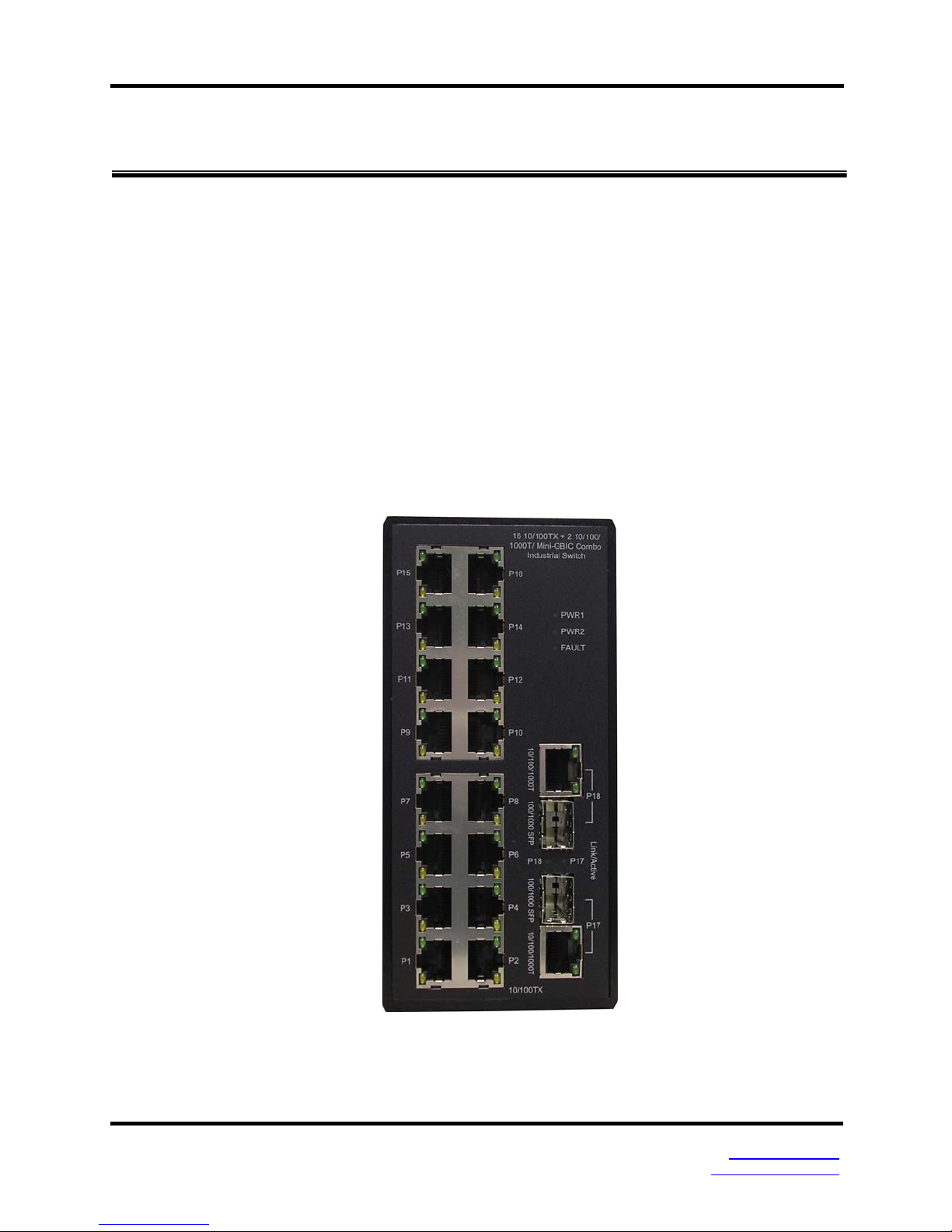
The EIR418-2SFP-T is an industrial DIN mount, unmanaged 18 port Ethernet switch with
Gigabit capability. It has (16) 10/100 copper Ethernet ports and (2) Gigabit Combo ports
that support copper or SFP module connections.
Features
• System Interface/Performance
o RJ-45 ports support Auto MDI/MDI-X Function
o SFP (mini-GBIC) supports 100/1000 Dual Mode
o Store-and-Forward Switching Architecture
o Back-plane (Switching Fabric): 7.2Gbps
o 1Mbits Packet Buffer
o 8K MAC Address Table
o Supports Wide Operating Temperature -40oC to 75oC
• Case/Installation
o IP30 Protection
o DIN-Rail and Wall Mount Design
• Power Supply
o Wide Range Redundant Power Design
o Power Reverse Polarity Protected
o Overload Current Protection
• Provides EFT protection 3,000 VDC for power line
• Supports 6,000 VDC Ethernet ESD protection
1 Manual Documentation Number EIR418-2SFP-T – 0109m
www.bb-elec.com
www.bb-europe.com

Package Contents
• (1) EIR418-2SFP-T, 18 Port Gigabit Industrial Ethernet Switch
• (1) Quick Start Guide
• (1) CD ROM with User Manual
• (2) Wall Mounting Bracket and Screws
Introduction
2 Manual Documentation Number EIR418-2SFP-T – 0109m
www.bb-elec.com
www.bb-europe.com
Physical Dimension
Hardware Description
Hardware Description
(W x D x H) is 72mm x 105mm x 152mm (2.8 x 4.1 x 6.0 inches)
Front Panel
The front panel of the EIR418-2SFP-T is shown below.
3 Manual Documentation Number EIR418-2SFP-T – 0109m
www.bb-elec.com
www.bb-europe.com
Hardware Description
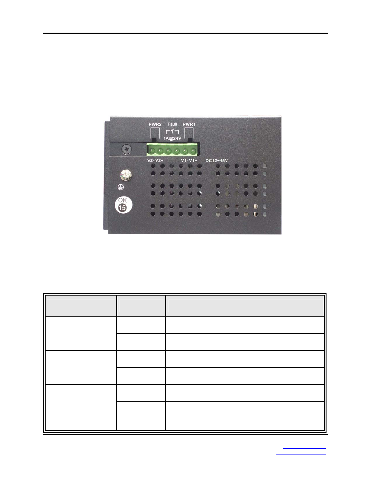
Top View
The top panel view of the EIR418-2SFP-T is equipped with one terminal block connector
that consists of two 12 to 48 VDC power inputs and the fault alarm output.
LED Indicators
LED Status Meaning
Green Power 1 is active
PWR1
Off No power at input 1
Green Power 2 is active
PWR2
Off No power at input 2
Red PWR1 or PWR2 has failed
Fault
Off
PWR1 & PWR2 are both active or no power is
applied
4 Manual Documentation Number EIR418-2SFP-T – 0109m
www.bb-elec.com
www.bb-europe.com

P1 to P16
Green
(Upper LED)
Blinking
(Upper LED)
Off
(Upper LED)
Hardware Description
Connected to network
Networking is active
Not connected to network
P17, P18
(10/100/1000T)
Yellow
(Lower LED)
Blinking
(Lower LED)
Off
(Lower LED)
Green
(Upper LED)
Blinking
(Upper LED)
Off
(Upper LED)
Green
(Lower LED)
Ethernet port full duplex
Collision of packets occurs
Ethernet port half duplex or not connected to
network
Connected to network
Networking is active
Not connected to network
The port is operating at speed of 1000M
Off
(Lower LED)
P17, P18
Link/Active
Green SFP port is connected to network
Blinking Networking is active
(100/1000 SFP)
Off Not connected to network
5 Manual Documentation Number EIR418-2SFP-T – 0109m
The port is disconnected or operates at speed of
10/100M
www.bb-elec.com
www.bb-europe.com
 Loading...