

Page 1
Manual
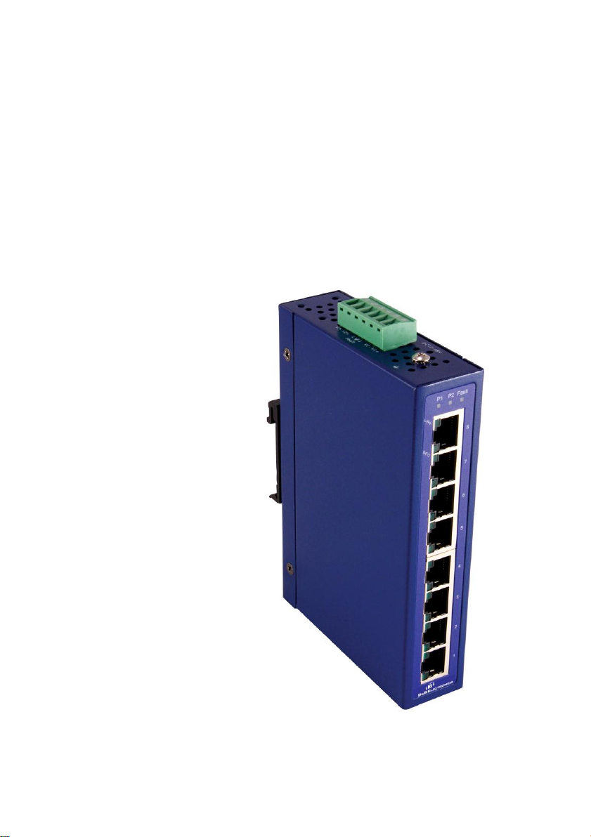
Elinx EIR408-T
8 Port-10/100/1000 Unmanaged Din Rail Ethernet Switch
Page 2

EIR408-T
Documentation Number: EIR408-T-4712m
International Headquarters:
707 Dayton Road
Ottawa, IL 61350 USA
Phone (815) 433-5100
Website: www.bb-elec.com
Sales e-mail: orders@bb-elec.com
Technical Support: support@bb.elec.com –
European Headquarters
B&B Electronics
Westlink Commercial Park
Oranmore, Co. Galway, Ireland
Phone +353 91-792444
Website: www.bb-europe.com
Sales e-mail: sales@bb-europe.com
Technical Support: support@bb-europe.com
Original – April 2011
©2011 No part of this publication may be reproduced or transmitted in any form or by any means,
electronic or mechanical, including photography, recording, or any information storage and retrieval
system without written consent. Information in this manual is subject to change without notice, and does
not represent a commitment on the part.
B&B Electronics Manufacturing shall not be liable for incidental or consequential damages resulting from
the furnishing, performance, or use of this manual. All brand names used in this manual are the
registered trademarks of their respective owners. The use of trademarks or other designations in this
publication is for reference purposes only and does not constitute an endorsement by the trademark
holder.
Page 3

Table of Contents
OVERVIEW .................................................................... 1
Features ....................................................................................................... 2
Package Check List .................................................................................... 2
HARDWARE DESCRIPTION ......................................... 3
Dimensions .................................................................................................. 3
WIRING THE POWER INPUTS ..................................... 4
LED Indicators ........................................................................................... 4
RJ45 ............................................................................................................. 5
RJ45 10/100/1000Base-T Pinouts .............................................................. 7
10/100/1000Base-T ...................................................................................... 8
Cabling ........................................................................................................ 8
MOUNTING INSTALLATION ....................................... 9
DIN-Rail Mounting .................................................................................... 9
Hanging the Industrial Switch ................................................................ 10
Wall-Mount Plate Mounting ................................................................... 11
Hardware Installation Diagram ................................ .............................. 12
Troubleshooting ........................................................................................ 13
Technical Specifications ........................................................................... 14
i
Page 4

Page 5

Overview
B&B Electronics Elinx family of Gigabit Industrial Din Rail mount
Ethernet switches have been designed to meet light and heavy Industrial
communication requirements.
High-Speed Transmissions
The Industrial switch includes a controller that can automatically sense
transmission speeds (10/100/1000 Mbps). The RJ45 copper ports support
auto MDI/MDIX operation. This feature allows network connections to
computers, servers, or other switches using straight-through or crossover
cables
All Ethernet ports have memory buffers that support the store-and-forward
mechanism. This assures that data is properly transmitted.
Dual Power Inputs
To reduce the risk of power failure, the Industrial switch provides 12 - 48
VDC dual power inputs. When power failure occurs, the device will
automatically switch to the secondary power input.
Flexible Mounting
The industrial switch is extremely compact and can be mounted on a dinrail or panel mounting making it suitable for any space-constrained
environment. Both mounting options are supplied with the Ethernet switch.
Wide Operating Temperature
The EIR408-T will operate in a -40 to 75C environment. The wide
temperature range will allow the EIR408-T to operate in some of the
harshest industrial environments that exist.
Easy Troubleshooting
LED indicators make troubleshooting quick and easy. Each 10/100/1000
port has 2 LED indicators that display the link status, transmission speed
and collision status. The power and fault LED’s add to the ease of
understanding operating conditions.
Manual Documentation Number: EIR408-T-4712m 1
B&B Electronics Mfg Co Inc – 707 Dayton Rd - PO Box 1040 - Ottawa IL 61350 - Ph 815-433-5100 - Fax 815-433-5104 – www.bb-elec.com
B&B Electronics – Westlink Commercial Park – Oranmore, Galway, Ireland – Ph +353 91-792444 – Fax +353 91-792445 – www.bb-europe.com
Page 6

Features
Provides 8 x 10/100/1000Base-T Mbps Ethernet ports.
Store-and-Forward switching architecture
Back-plane (switching fabric): 16Gbps
Provides 176Kbits memory buffer
8K-entry MAC address table
9.6K bytes jumbo frame
Supports full/half duplex flow control
Supports broadcast storm protection
Supports MDI/MDI-X auto-crossover
Supports redundant +12 - 48 VDC power input
Provides flexible mounting: DIN-rail, Panel Mounting
Supports operating temperatures of -40 ~ 75oC
Package Check List
8-port 10/100/1000Base-T Industrial Ethernet Switch
User Manual
Quick Start Guide
Wall Mounting Brackets with screws
2 Manual Documentation Number: EIR408-T-4712m
B&B Electronics Mfg Co Inc – 707 Dayton Rd - PO Box 1040 - Ottawa IL 61350 - Ph 815-433-5100 - Fax 815-433-5104 – www.bb-elec.com
B&B Electronics – Westlink Commercial Park – Oranmore, Galway, Ireland – Ph +353 91-792444 – Fax +353 91-792445 – www.bb-europe.com
Page 7

Hardware Description
The following information is an introduction to the Gigabit Industrial
Ethernet Switch dimensions, ports, cabling information, and wiring
installation.
Dimensions
The dimensions of the industrial switch are 30 x 140 x 95 mm (W x H x D).
The figure below gives the dimensions and views of each side of the 8-port
10/100/1000Base-T Industrial Ethernet switch.
Manual Documentation Number: EIR408-T-4712m 3
B&B Electronics Mfg Co Inc – 707 Dayton Rd - PO Box 1040 - Ottawa IL 61350 - Ph 815-433-5100 - Fax 815-433-5104 – www.bb-elec.com
B&B Electronics – Westlink Commercial Park – Oranmore, Galway, Ireland – Ph +353 91-792444 – Fax +353 91-792445 – www.bb-europe.com
Page 8

V- V+
V- V+
LED
Color
Description
P1
Green
On
Power input 1 is active
Off
Power input 1 is inactive
P2
Green
On
Power input 2 is active
Off
Power input 2 is inactive
Fault
Red
On
Power input 1 or 2 is inactive
Off
Power input 1 and 2 are both
functional, or no power inputs
1 ~ 8
(Upper LED)
Green
On
Connected to network
Flashing
Networking is active
Off
Not connected to network
1 ~ 8
(Lower LED)
Green
On
Connected to network at speed of
1000Mbps
Off
Not connected to network or not
working at speed of 1000Mbps
Wiring the Power Inputs
Note: Terminal blocks are rated for 12-24 AWG wire
LED Indicators
The LED indicators located on the front panel display the power and
network status of the Industrial switch. Refer to the chart below for LED
description and operation.
4 Manual Documentation Number: EIR408-T-4712m
B&B Electronics Mfg Co Inc – 707 Dayton Rd - PO Box 1040 - Ottawa IL 61350 - Ph 815-433-5100 - Fax 815-433-5104 – www.bb-elec.com
B&B Electronics – Westlink Commercial Park – Oranmore, Galway, Ireland – Ph +353 91-792444 – Fax +353 91-792445 – www.bb-europe.com
Page 9

RJ45
The RJ45 copper ports support auto MDI/MDIX operation. This feature
allows network connections to computers, servers, or other switches using
straight-through or crossover cables (See Figure below). Straight-through
cable connections: pins 1, 2, 3 and 6, at one end of the cable, are connected
straight-through to pins 1, 2, 3 and 6 at the other end of the cable. The table
below shows the 10BASE-T/100BASE-TX MDI and MDI-X port pin outs.
Manual Documentation Number: EIR408-T-4712m 5
B&B Electronics Mfg Co Inc – 707 Dayton Rd - PO Box 1040 - Ottawa IL 61350 - Ph 815-433-5100 - Fax 815-433-5104 – www.bb-elec.com
B&B Electronics – Westlink Commercial Park – Oranmore, Galway, Ireland – Ph +353 91-792444 – Fax +353 91-792445 – www.bb-europe.com
Page 10

6 Manual Documentation Number: EIR408-T-4712m
B&B Electronics Mfg Co Inc – 707 Dayton Rd - PO Box 1040 - Ottawa IL 61350 - Ph 815-433-5100 - Fax 815-433-5104 – www.bb-elec.com
B&B Electronics – Westlink Commercial Park – Oranmore, Galway, Ireland – Ph +353 91-792444 – Fax +353 91-792445 – www.bb-europe.com
Page 11

Pin
Signal
name
Description
1
BI_DA+
Bi-directional pair A+
2
BI_DA-
Bi-directional pair A-
3
BI_DB+
Bi-directional pair B+
4
BI_DC+
Bi-directional pair C+
5
BI_DC-
Bi-directional pair C-
6
BI_DB-
Bi-directional pair B-
7
BI_DD+
Bi-directional pair D+
8
BI_DD-
Bi-directional pair D-
RJ45 10/100/1000Base-T Pinouts
The table below describes gigabit Ethernet RJ-45 pinouts.
Manual Documentation Number: EIR408-T-4712m 7
B&B Electronics Mfg Co Inc – 707 Dayton Rd - PO Box 1040 - Ottawa IL 61350 - Ph 815-433-5100 - Fax 815-433-5104 – www.bb-elec.com
B&B Electronics – Westlink Commercial Park – Oranmore, Galway, Ireland – Ph +353 91-792444 – Fax +353 91-792445 – www.bb-europe.com
Page 12

10/100/1000Base-T
The following two figures illustrate the 10/100/1000Base-T cable schema.
Straight Through Cable Schema
Crossover Cable Schema
Cabling
Use unshielded twisted-pair (UTP) or shielded twisted-pair (STP) cable for
RJ-45 connections: 100Ω Category 3, 4 or 5 cable for 10Mbps
connections, 100Ω Category 5 cable for 100Mbps, or 100Ω Category
5e/above cable for 1000Mbps connections.
The cable between the switch and the link partner (switch, hub,
workstation, etc.) must be less than 100 meters (328 ft.) long.
8 Manual Documentation Number: EIR408-T-4712m
B&B Electronics Mfg Co Inc – 707 Dayton Rd - PO Box 1040 - Ottawa IL 61350 - Ph 815-433-5100 - Fax 815-433-5104 – www.bb-elec.com
B&B Electronics – Westlink Commercial Park – Oranmore, Galway, Ireland – Ph +353 91-792444 – Fax +353 91-792445 – www.bb-europe.com
Page 13

Rear Panel of the
switch
DIN-rail clip
Mounting Installation
DIN-Rail Mounting
The din-rail clip is factory installed with removable screws.
B&B Electronics – Westlink Commercial Park – Oranmore, Galway, Ireland – Ph +353 91-792444 – Fax +353 91-792445 – www.bb-europe.com
Manual Documentation Number: EIR408-T-4712m 9
B&B Electronics Mfg Co Inc – 707 Dayton Rd - PO Box 1040 - Ottawa IL 61350 - Ph 815-433-5100 - Fax 815-433-5104 – www.bb-elec.com
Page 14

Hanging the Industrial Switch
First, position the din-rail clip of the switch directly in front of the DIN rail.
Make sure the top of the clip hooks over the top of the DIN rail.
Push the unit downward.
Check to see that the DIN-Rail clip is tightly fixed on the DIN rail.
To remove the industrial switch from the track, reverse the steps above.
10 Manual Documentation Number: EIR408-T-4712m
B&B Electronics Mfg Co Inc – 707 Dayton Rd - PO Box 1040 - Ottawa IL 61350 - Ph 815-433-5100 - Fax 815-433-5104 – www.bb-elec.com
B&B Electronics – Westlink Commercial Park – Oranmore, Galway, Ireland – Ph +353 91-792444 – Fax +353 91-792445 – www.bb-europe.com
Page 15

Wall-Mount Plate Mounting
1. When using the wall mount plates the din-rail clip can be
removed.
2. Place the wall-mount plates on the rear panel of the industrial
switch and fasten the screws.
Manual Documentation Number: EIR408-T-4712m 11
B&B Electronics Mfg Co Inc – 707 Dayton Rd - PO Box 1040 - Ottawa IL 61350 - Ph 815-433-5100 - Fax 815-433-5104 – www.bb-elec.com
B&B Electronics – Westlink Commercial Park – Oranmore, Galway, Ireland – Ph +353 91-792444 – Fax +353 91-792445 – www.bb-europe.com
Page 16

Hardware Installation Diagram
12 Manual Documentation Number: EIR408-T-4712m
B&B Electronics Mfg Co Inc – 707 Dayton Rd - PO Box 1040 - Ottawa IL 61350 - Ph 815-433-5100 - Fax 815-433-5104 – www.bb-elec.com
B&B Electronics – Westlink Commercial Park – Oranmore, Galway, Ireland – Ph +353 91-792444 – Fax +353 91-792445 – www.bb-europe.com
Page 17

Troubleshooting
Do not use the power adapter with DC output higher than the power
rating of the device.
Select the proper UTP/STP cable to construct your network. Use
unshielded twisted-pair (UTP) or shielded twisted-pair (STP) cable
for RJ-45 connections: 100Ω Category 3, 4 or 5 cable for 10Mbps
connections, 100Ω Category 5 cable for 100Mbps, or 100Ω
Category 5e/above cable for 1000Mbps connections. Insure the
length of any twisted-pair connection does not exceed 100 meters
(328 feet).
Diagnosing LED Indicators: The Switch can be easily monitored
through panel LED’s. The LED’s will provide an easy way of
detecting power or communication problems.
During loss or no communications verify the Industrial switch LED
indicators are displaying normal operating status. Next perform the
ping test to confirm connection and status of device connections on
the network.
Manual Documentation Number: EIR408-T-4712m 13
B&B Electronics Mfg Co Inc – 707 Dayton Rd - PO Box 1040 - Ottawa IL 61350 - Ph 815-433-5100 - Fax 815-433-5104 – www.bb-elec.com
B&B Electronics – Westlink Commercial Park – Oranmore, Galway, Ireland – Ph +353 91-792444 – Fax +353 91-792445 – www.bb-europe.com
Page 18

Communications
Compatibility
IEEE 802.3, 802.3u, 802.3ab
IEEE 802.3x
LAN
10/100/1000Base-T
Back-plane (Switching
Fabric)
16 Gbps
Packet Throughput (Fullduplex)
23.8Mpps @ 64bytes
Transmission Distance
Up to 100 m
Transmission Speed
Up to 1000 Mbps
Broadcast Storm Rate
Limit
7,926pps (default)
Interface
Connectors
8 x RJ-45 (8-port 10/100/1000TX)
6-pin removable screw terminal (power & relay)
LED Indicators
Unit: P1, P2, Fault
Ethernet port: Link/Active, Speed
Power
Power Consumption
7.788 W
Power Input
2 x Unregulated +12 ~ 48 VDC
Fault Output
1 Relay Output
Mechanism
Dimensions (WxHxD)
30 x 140 x 95 mm
Enclosure
IP-30, Metal shell with solid mounting
kits
Environment
Technical Specifications
14 Manual Documentation Number: EIR408-T-4712m
B&B Electronics Mfg Co Inc – 707 Dayton Rd - PO Box 1040 - Ottawa IL 61350 - Ph 815-433-5100 - Fax 815-433-5104 – www.bb-elec.com
B&B Electronics – Westlink Commercial Park – Oranmore, Galway, Ireland – Ph +353 91-792444 – Fax +353 91-792445 – www.bb-europe.com
Page 19

Operating Temperature
-10 ~ 60oC (standard model)
-40 ~ 75oC (wide operating temperature model)
Operating Humidity
5% ~ 95% (non-condensing)
Storage Temperature
-40 ~ 85oC
Certifications
Safety
CE EN60950-1
Hazardous Location
UL/cUL Class I, Division 2, Groups A, B, C and D
EMC
FCC Class A,
CE EN61000-4-2 (ESD)
CE EN61000-4-3 (RS)
CE EN61000-4-4 (EFT)
CE EN61000-4-5 (Surge)
CE EN61000-4-6 (CS)
CE EN61000-4-8
CE EN61000-6-2
CE EN61000-6-4
Free Fall
IEC60068-2-32
Shock
IEC60068-2-27
Vibration
IEC60068-2-6
Manual Documentation Number: EIR408-T-4712m 15
B&B Electronics Mfg Co Inc – 707 Dayton Rd - PO Box 1040 - Ottawa IL 61350 - Ph 815-433-5100 - Fax 815-433-5104 – www.bb-elec.com
B&B Electronics – Westlink Commercial Park – Oranmore, Galway, Ireland – Ph +353 91-792444 – Fax +353 91-792445 – www.bb-europe.com
 Loading...