

Page 1
AirborneM2M™
APXx-Q5xxx Family User Manual
Revision: 1.1
June 2013
File Name: APXx_Family_User_Manual_R1.1_2213
Page 2

B&B Electronics, Inc. AirborneM2M™ User Manual
International Headquarters
B&B Electronics Mfg. Co. Inc.
707 Dayton Road
Ottawa, IL 61350 USA
Phone (815) 433-5100 -- General Fax (815) 433-5105
Website: www.bb-elec.com
European Headquarters
B&B Electronics Ltd.
Westlink Commercial Park
Oranmore, Co. Galway, Ireland
Phone +353 91-792444 -- Fax +353 91-792445
Website: www.bb-europe.com
2 1/9/2014
Page 3

AirborneM2M™ Users Guide B&B Electronics, Inc.
Contents
1.0 Conventions ................................................................................................................................... 7
1.1 Terminology ................................................................................................................................ 7
1.2 Notes ............................................................................................................................................ 7
1.3 Caution ......................................................................................................................................... 7
1.4 File Format .................................................................................................................................. 7
2.0 Product Description ....................................................................................................................... 8
3.0 Features .......................................................................................................................................... 9
4.0 Device Types ................................................................................................................................10
4.1 Serial ...........................................................................................................................................10
4.2 Ethernet ......................................................................................................................................10
4.3 Flexport™ ...................................................................................................................................10
4.4 Industrial Packaging ..................................................................................................................10
5.0 Pinout and Connectors ................................................................................................................12
5.1 Serial Ports .................................................................................................................................12
5.2 Ethernet Port ..............................................................................................................................13
5.3 Connector Definition .................................................................................................................14
5.4 Default Switch (Factory Reset)................................................................................................14
5.5 Indicator LEDs ...........................................................................................................................15
6.0 Electrical& RF Specification ........................................................................................................16
6.1 AC Electrical Characteristics – Transmitter ...........................................................................18
6.2 Performance/Range ..................................................................................................................18
7.0 Antenna ..........................................................................................................................................19
7.1 Antenna Selection .....................................................................................................................19
7.2 Antenna Location ......................................................................................................................19
7.3 Performance ...............................................................................................................................20
To learn more about Link Margin, visit B&B Electronics’ online technical library. .........................20
8.0 Mechanical Outline – Industrial Class .......................................................................................21
9.0 Getting Started ..............................................................................................................................22
9.1 Unpack the AirborneM2M™ Device .......................................................................................22
10.0 Setup (APXx-Q542x) ...................................................................................................................23
11.0 Using the Web Interface ..............................................................................................................28
11.1 Navigation Bar ...........................................................................................................................29
11.2 Feature Links .............................................................................................................................30
11.3 Navigating the Website.............................................................................................................30
11.4 Updating a Field ........................................................................................................................31
11.5 Uploading Certificates...............................................................................................................31
11.6 Upload Configuration Files .......................................................................................................32
11.7 Updating Firmware .................................................................................................................... 34
12.0 Express Setup Configuration Page ............................................................................................37
13.0 Configuring the Wireless Interface .............................................................................................41
1/9/2014 3
Page 4

B&B Electronics, Inc. AirborneM2M™ User Manual
14.0 Configuring the Security Settings ...............................................................................................42
14.1 Configuring for WEP Security ..................................................................................................42
14.2 Configuring for WPA-PSK Security ........................................................................................42
14.3 Configuring for WPA2-PSK Security ......................................................................................43
15.0 Configuring the Serial Device Server ........................................................................................45
15.1 Configuring Serial Port for Access on Telnet Port ................................................................45
15.2 Configuring Serial Port 1 for Access on Tunnel Port ...........................................................46
15.3 Configuring Serial Port 2 for Access on Tunnel Port ...........................................................47
15.4 Configuring Serial Port 1 as TCP Client.................................................................................48
15.5 Configuring Serial Port 2 as TCP Client.................................................................................50
16.0 Web Page Overview ....................................................................................................................52
Module Status ........................................................................................................................ 53
Ethernet Status ...................................................................................................................... 54
Radio Statistics ...................................................................................................................... 55
Ethernet Statistics .................................................................................................................. 56
Display Associated Clients .................................................................................................... 57
Wireless DHCP Clients .......................................................................................................... 58
Express Setup ....................................................................................................................... 59
WLAN Settings ...................................................................................................................... 60
WLAN Security Settings ........................................................................................................ 61
Network Settings .................................................................................................................... 62
Serial Port Settings ................................................................................................................ 63
Serial Port 2 Settings ............................................................................................................. 64
Connection Settings............................................................................................................... 65
Ethernet Settings ................................................................................................................... 67
Event Settings ........................................................................................................................ 68
Port Forwarding Settings ....................................................................................................... 69
IP Filtering Settings................................................................................................................ 70
Advanced Settings ................................................................................................................. 71
Upload Configuration File ...................................................................................................... 75
List Configuration File ............................................................................................................ 76
Delete Configuration File ....................................................................................................... 77
Active Configuration............................................................................................................... 78
User Configuration ................................................................................................................. 79
OEM Configuration ................................................................................................................ 80
Factory Configuration ............................................................................................................ 81
WPA Configuration ................................................................................................................ 82
List Certificates ...................................................................................................................... 83
Upload Certificate .................................................................................................................. 84
Delete Certificate ................................................................................................................... 85
Network (Home Page) ........................................................................................................... 86
Discover Airborne Modules ................................................................................................... 87
Scan for Access Points .......................................................................................................... 88
Maintenance (Home Page) .................................................................................................... 89
Update Module Firmware ...................................................................................................... 90
Reset Factory Defaults .......................................................................................................... 91
Restart Module ...................................................................................................................... 92
Set System Time ................................................................................................................... 93
Blink the POST LED .............................................................................................................. 94
Stop Blinking the POST LED ................................................................................................. 95
Upload Script Files ................................................................................................................. 96
4 1/9/2014
Page 5

AirborneM2M™ Users Guide B&B Electronics, Inc.
List Script Files ...................................................................................................................... 97
Display Script Files ................................................................................................................ 98
Delete Script File ................................................................................................................... 99
Run Script File ..................................................................................................................... 100
17.0 Certification & Regulatory Approvals .......................................................................................101
17.1 FCC Statement ........................................................................................................................101
17.2 FCC RF Exposure Statement ................................................................................................102
17.3 Information for Canadian Users (IC Notice) ........................................................................102
17.4 FCC/IC Modular Approval ......................................................................................................103
17.5 Regulatory Test Mode Support .............................................................................................104
18.0 Physical & Environmental Approvals .......................................................................................105
1/9/2014 5
Page 6

B&B Electronics, Inc. AirborneM2M™ User Manual
Figures
Figure 1 - Industrial AirborneM2M™ Device ..........................................................................................11
Figure 2- DE-9 (DB-9) Connector Pin-out ...............................................................................................12
Figure 3 - Ethernet Jack Pinout ................................................................................................................13
Figure 4 - Website Login ............................................................................................................................28
Figure 5 - Default Home Page ..................................................................................................................29
Figure 6- Website Navigation Bar ............................................................................................................29
Figure 7- Feature Links .............................................................................................................................. 30
Figure 8 - Airborne Web Page ..................................................................................................................30
Figure 9 - Upload Certificate Web Page..................................................................................................31
Figure 10 - Upload Configuration Web Page ..........................................................................................33
Figure 11 - Firmware Update Page ................................................................ ................................ ..........34
Figure 12 - Firmware Update in Progress ...............................................................................................35
Figure 13 - Firmware Update Complete ................................................................................................ ..35
Figure 14 - Express Setup Page ..............................................................................................................37
Tables
Table 1–Serial Port Pin Definition ............................................................................................................12
Table 2 - Ethernet Connector Pinout .......................................................................................................13
Table 3 - PoE Pinout Alternatives ............................................................................................................13
Table 4 - Connector Description ...............................................................................................................14
Table 5 - Reset Procedure ........................................................................................................................14
Table 6 - LED Indicators ............................................................................................................................15
Table 7- Absolute Maximum Values1 .......................................................................................................16
Table 8 - RF Characteristics – 802.11a/b/g/n .........................................................................................16
Table 9 - Supported Data Rates by Band ...............................................................................................17
Table 10 - Operating Channels................................................................................................ .................17
Table 11 - Radio Typical Performance Range .......................................................................................18
Table 12- APXx Accessing the Web Interface ......................................................................................23
Table 13 - Navigation Bar Items ...............................................................................................................29
Table 14 - Uploading Certificates .............................................................................................................32
Table 15 - Uploading Configurations .......................................................................................................33
Table 16 - Updating Firmware ..................................................................................................................35
Table 17 - Express Page Setup ................................................................................................................37
Table 18 - Configuring for WEP Security ................................................................................................42
Table 19 - Configuring for WPA Security ................................................................................................43
Table 20 - Configuring for WPA2 Security ..............................................................................................43
Table 21–Configure Data Tunnel on Telnet Port ...................................................................................45
Table 22 - Data Tunnel using Telnet Port ...............................................................................................46
Table 23 – Configure Data Tunnel on Serial Port 1 Tunnel Port (TCP) .............................................46
Table 24 - Data Tunnel using Tunnel Port on Serial Port 1 ..................................................................47
Table 25 – Configure Data Tunnel on Serial Port 2 Tunnel Port (TCP) .............................................47
Table 26 - Data Tunnel using Tunnel Port on Serial Port 2 ..................................................................48
Table 27 - Configure Serial Port 1 as TCP Client ..................................................................................49
Table 28 - Configure Serial Port 2 as TCP Client ..................................................................................50
Table 29 - Regulatory Approvals ............................................................................................................101
Table 30 - Modular Approval Grant Numbers ......................................................................................103
Table 31 - Mechanical Approvals ...........................................................................................................105
6 1/9/2014
Page 7

AirborneM2M™ Users Guide B&B Electronics, Inc.
The area next to the indicator will identify the specific information and make any
references necessary.
The area next to the indicator will identify the specific information and make any
references necessary.
1.0 Conventions
The following section outlines the conventions used within the document. Where
convention is deviated from, the deviation takes precedence and should be followed. If
you have any question related to the conventions used or clarification of indicated
deviation please contact B&B Electronics Sales or Wireless Support.
1.1 Terminology
APXx-Q5xxx is used in the opening section to describe the device detailed in this
document. After this section the term module or device will be used to describe
the device.
1.2 Notes
A note contains information that requires special attention. The following
convention will be used. The area next to the indicator will identify the specific
information and make any references necessary.
1.3 Caution
A caution contains information that, if not followed, may cause damage to the
product or injury to the user. The shaded area next to the indicator will identify
the specific information and make any references necessary.
1.4 File Format
These documents are provided as Portable Document Format (PDF) files. To
read them, you need Adobe Acrobat Reader 4.0.5 or higher. For your
convenience, Adobe Acrobat Reader is provided on the software CD. Should you
not have the CD, you can download the latest version of Adobe Acrobat Reader
at the Adobe Web site: www.adobe.com
1/9/2014 7
Page 8

B&B Electronics, Inc. AirborneM2M™ User Manual
2.0 Product Description
B&B Electronics' APXx-Q5xxx industrial grade access point enables a piece of M2M
equipment to become the center of a self-sufficient Wi-Fi network. This makes it easy to
access equipment data as well as resources from other Wi-Fi enabled devices, like
laptops, tablets and handhelds. The other devices can be powered by Android, iOS or
Windows. The APXx-Q5xxx includes a 10/100 Ethernet port that supports both bridge
and router modes, and two serial ports that are compatible with RS232/422/485 devices.
Users may make multiple connections to the same machine, and all ports may be used
simultaneously in any serial data configuration. This allows the APXx-Q5xxx to provide
more port configuration options than any competing device in the industry.
The APXx-Q5xxx also includes a wide range power supply input (5-36 VDC) with terminal
block and barrel jack connections. It is packaged in a rugged metal enclosure. The
APXx-Q54x8 models support 802.3af Class 1 based Power over Ethernet (PoE).
The Airborne™ family of access points includes models with single band or dual band
radios: the APXG supports 802.11b/g and the APXN supports 802.11a/b/g/n.
B&B Electronics is the industry leader in industrial grade 802.11 wireless serial-toEthernet converters, access points, Ethernet bridges and Ethernet adapters. The APXxQ5xxx is the newest member of B&B Electronics' Airborne™ series, a family of fully
integrated 802.11 wireless LAN bridge, serial device server, and access point products
designed to provide wireless LAN and Internet connectivity in industrial, scientific,
medical and automotive applications. The highly integrated hardware and software
enables plug-and-play capability and significantly reduces the complexity of wireless
system deployment and network connectivity.
All Airborne™ 802.11 access point products include Airborne Management Center
software for web browser-based configuration and administration. The Airborne
Management Center makes it easy to install and configure Airborne devices. The same
interface is employed across the entire product line. If you’ve used one Airborne device,
you know how to use them all.
8 1/9/2014
Page 9

AirborneM2M™ Users Guide B&B Electronics, Inc.
3.0 Features
Wi-Fi Radio with 32-bit ARM9 CPU (256Mb SDRAM, 64Mb Flash)
APXG models support 802.11b/g
APXN models support 802.11a/b/g/n
Fully functional M2M Access Point and Wireless Router.
Software selectable as AirborneM2M™ or AirborneDirect™ client device
server.
Integrated Airborne Device Server and Wireless Adapter technology.
The AirborneM2M™ Access Point supports integrated:
802.11 radio
TCP/IP stack, UDP, telnet, FTP server
Ethernet bridge mode (Access Point)
Ethernet router mode (Wireless Router)
Dual Serial ports (RS232/422/485)
Data bridging and buffering
Command Line Interface
Web interface
WEP/WPA/WPA2-PSKSecurity
DHCP Server (For wireless clients)
Firewall and Port Forwarding (Ethernet Router Mode)
Transmit RF power control
FTP Server
Operating Temperature(-40°C to 85°C)
Storage temp (-40°C to 85°C)
Industry standard wired connections:
D-9 Serial connectors (RS232/422/485)
RJ-45 (10/100 Ethernet)
Multiple host interfaces supported:
Dual Serial (RS232/422/485) – up to 921K BAUD
10/100 Ethernet
Dual RP-SMA antenna connectors.
Integrated standard and wide range (J1455) Power Supply (5-36VDC)
Power connector options include 2.1mm Barrel Jack, Terminal Block
Power Over Ethernet (PoE) using an 802.3af Class 1 PSE device (APXx-
Q5xx8 models)
Integrated Site Survey mode.
Advanced Low power modes.
Rugged mounting options.
Worldwide Regulatory Support (FCC, IC, CE)
1/9/2014 9
Page 10

B&B Electronics, Inc. AirborneM2M™ User Manual
4.0 Device Types
This manual covers the AirborneM2M™ Access Point/Wireless Router/Client. Information
on the variations and functionality available in the AirborneDirect™ device family can be
found in the ABDN Family User Manual. If you are not certain which type you have or
would like clarification on the available options please contact B&B Sales or Technical
Support.
The AirborneM2M™ supports the following host interfaces:
4.1 Serial
This device supports dual serial ports and provides serial to 802.11 bridging. The
following serial interface types are available:
RS-232
RS-422
RS-485
Default configuration is RS-232. Conversion to RS-422/485 is software
selectable. Changing the serial port configuration is covered later in the manual.
4.2 Ethernet
The Ethernet adapter provides a wireless interface to an existing Ethernet port
(RJ-45). The connection to the Ethernet port of the host is made via the RJ-45
socket.
The device supports a 10/100 Ethernet interface with auto configuration. Manual
control of the interface is possible through the web or CLI interface.
4.3 Flexport™
This AirborneM2M™ allows for simultaneous connection of Serial and Ethernet
ports in any combination. You may maintain network-based connections to both
the Ethernet and Serial ports without compromising functionality or performance.
Each interface can be configured and operated independently of the others.
Connection to the serial port can be made via both the wireless and Ethernet
ports. In this mode the device is capable of supporting redundant network
connectivity for high reliability applications.
4.4 Industrial Packaging
Developed to support the demands of the industrial and automotive
environments, the packaging supports the full industrial operating temperature
range and the complete set of functional capabilities of the Airborne Access
Point, Airborne Device Server and Wireless Adapter technology.
10 1/9/2014
Page 11

AirborneM2M™ Users Guide B&B Electronics, Inc.
Figure 1 - Industrial AirborneM2M™ Device
The device includes a metal enclosure and a wide range power supply capable
of exceeding the SAE J1455 power supply requirements.
The industrial packaging is ideal for the following application types:
CNC/DNC equipment.
Vehicle diagnostics.
Telematics.
Remote monitoring and management.
Industrial control.
1/9/2014 11
Page 12

B&B Electronics, Inc. AirborneM2M™ User Manual
Pin
RS232 (DTE)
RS232 w/Power
on pin 9
2
RS422/RS485
4-wire
RS485
2-wire
1
No Connect
No Connect
No Connect
No Connect
2
RxD
RxD
RxD+
Connect to pin 33
3
TxD
TxD
TxD+
TxD+/RxD+
4
No Connect
No Connect
No Connect
No Connect
5
GND
GND
GND
GND
6
No Connect
No Connect
RxD-
Connect to pin 93
7
RTS
RTS
No Connect
No Connect
8
CTS
CTS
No Connect
No Connect
9
No Connect
5VDC (Input)
TxD-
TxD-/RxD-
1. For 2-wire operation, the user must externally connect pin 3 to pin 2 and
pin 6 to pin 9.
5.0 Pinout and Connectors
The following defines the pinouts for the wired interfaces.
5.1 Serial Ports
The AirborneM2M™ unit supports two serial ports. The Port pinout can change
depending upon the interface configuration chosen. Table 1 shows the pinout for
the interface selected.
Figure 2- DE-9 (DB-9) Connector Pin-out
Table 1–Serial Port Pin Definition
The Port 1 and Port 2 interfaces support the following configurations:
BAUD: 300, 600, 1200, 2400, 4800, 9600, 14400, 19200, 28800, 38400,
57600, 115200, 230400, 460800, 921600
Flow Control: None, Hardware (CTS/RTS), Software (XON/XOFF)
Port 1 Default settings: 9600, 8, N, 1, No Flow Control.
Port 2 Default settings: 9600, 8, N, 1, No Flow Control.
12 1/9/2014
Page 13

AirborneM2M™ Users Guide B&B Electronics, Inc.
Pin
RJ45 Socket
1
TxD+
2
TxD-
3
RxD+ 4 NC 5 NC
6
RxD- 7 NC 8 NC
Green LED
Unused
Yellow LED
Ethernet Link/Activity:
Off No Ethernet Link
On Ethernet Link active
Flashing Network activity
Pin
Alternate A
(MDI-X)
Alternate A
(MDI)
Alternate B
(All)
1
Negative V
PSE
Positive V
PSE
2
Negative V
PSE
Positive V
PSE
3
Positive V
PSE
Negative V
PSE
4
Positive V
PSE
5
Positive V
PSE
6
Positive V
PSE
Negative V
PSE
7
Negative V
PSE
8
Negative V
PSE
5.2 Ethernet Port
The AirborneM2M™10/100Mbps interface supports auto negotiation. The
interface also supports both half and full duplex for 10Mbps and 100Mbps.Table
2 shows the interface pinout.
In some models, the Ethernet port supports Power over Ethernet (PoE) when
connected to an 802.3af Class 1 PSE device. Both Mode A (MDI and MDI-X) and
Mode B powering schemes are supported (Table 3).
Figure 3 - Ethernet Jack Pinout
Table 2 - Ethernet Connector Pinout
1/9/2014 13
Table 3 - PoE Pinout Alternatives
Page 14

B&B Electronics, Inc. AirborneM2M™ User Manual
Type
Description
Serial
DE-9 Connector Male
Ethernet
RJ45 Socket
Antenna
RP-SMA
Power
2.1mm Barrel Jack
Power
2 Position Terminal Block
1
Disconnect or turn off the power supply.
2
Press and hold in the Default (factory reset) button.
This may require the use of a small, narrow object. Do not use anything sharp, as
that may damage the unit.
3
While the Default button is pressed and held in, re-apply power to the unit.
4
Continue to hold in the Default button for 5-6 seconds after power has been
applied.
5
Release the Default button.
5.3 Connector Definition
The AirborneM2M™ device has five connectors. Table 4 provides definitions for
the connectors.
Table 4 - Connector Description
5.4 Default Switch (Factory Reset)
The AirborneM2M™ device will let you reset the configuration back to OEM
defaults and start over again. This is useful when a device has been incorrectly
configured. An incorrect configuration can make it impossible to communicate on
any of the available ports. That would prevent access to the configuration
interfaces and block your ability to correct the configuration.
Performing a Factory RESET will return the device to the original OEM defaults.
If no OEM configuration is installed the device will return to the B&B factory
defaults. That will restore your ability to communicate with the device.
The following Table 5 describes the sequence for resetting the AirborneM2M™
device to the OEM defaults
Table 5 - Reset Procedure
14 1/9/2014
Page 15
AirborneM2M™ Users Guide B&B Electronics, Inc.
6
The device will restart with the installed OEM defaults. If no OEM configuration
exists the device will return to B&B Electronics factory defaults.
See section 11.6 on use of OEM factory configurations.
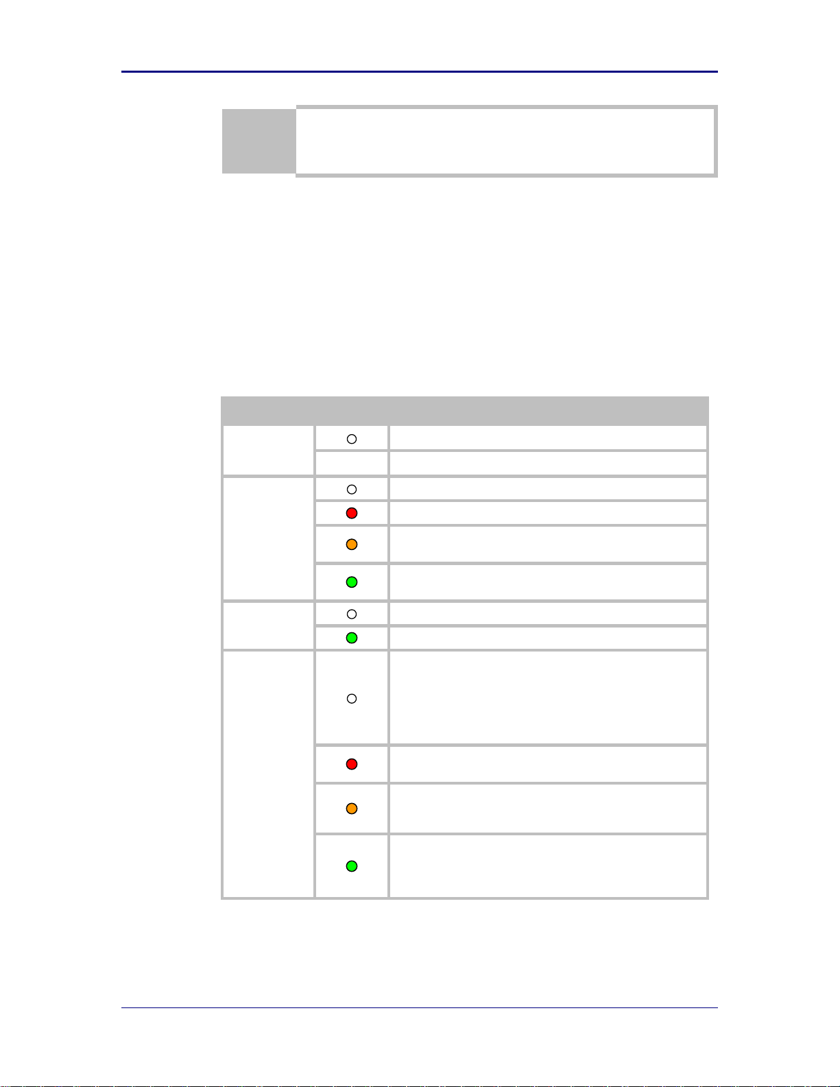
LED
Color
Airborne Device State
POWER
Adapter is not powered.
(Blue) Adapter is powered.
POST
Adapter is not powered.
(Red) Adapter failed Power On Self Test (POST).
(Orange) Adapter passed POST but is not configured for
wireless network communication.
(Green) Adapter passed POST and is configured for wireless
AP communication.
LINK
Adapter is not powered or the Wireless radio is off.
(Green) Adapter is powered and the Wireless radio is on.
COMM
• If Power LED and COMM LED are both Off the Adapter is not
powered.
• If Power LED is On but the COMM LED is Off, it means that
an Ethernet link has been detected, but no TCP session from
the WLAN or Ethernet interface has been established. The
LED will flash Red when Ethernet network traffic occurs.
(Red) The device is powered and no Ethernet link has been
detected.
(Orange) A TCP connection to the adapter has been
established from the Wireless interface and no Ethernet link
has been detected.
(Green) A TCP connection to the adapter has been established
from the Wireless or Ethernet interface. An Ethernet link has
been detected. The LED will flash Orange when Ethernet
network traffic occurs.
The AirborneM2M™ Default button is on the Ethernet/Power end of the box, next
to the 2.1mm barrel connector (See section 8.0)
5.5 Indicator LEDs
The indicator LEDs provide feedback on the state of the device when it is
configured as an AP/WR. If the device is configured for any other operation
please refer to the appropriate device manual. The LEDs are a useful tool during
installation and troubleshooting.
Table 6 - LED Indicators
1/9/2014 15
Page 16

B&B Electronics, Inc. AirborneM2M™ User Manual
Parameter
Min
Max
Unit
Maximum Supply Voltage
5.0
36
VDC
PoE 802.3af Class1 – Q5xx8 models
37
57
VDC
Power Dissipation
3.00
W
Operating Temperature Range
-40
85 oC
Storage Temperature
-40
85 oC
Symbol
Parameter
Rate (Mb/s)
Min
Average
dBm / mW
Peak
dBm / mW
Units
P
OUTB
Transmit Power
Output 802.11b
11, 5.5, 2, 1
15.0
31.6
dBm
P
OUTG
Transmit Power
Output 802.11g
6, 9, 12, 18, 24,
36, 48, 54
12.6
18.2
dBm
P
OUTA
Transmit Power
Output 802.11a
6, 9, 12, 18, 24,
36, 48, 54
17.0
50.1
dBm
P
RSENB
Receive
Sensitivity
802.11b
11 -86
dBm
1 -92
P
RSENG
Receive
Sensitivity
802.11g
54 -72
dBm
36 -78 18 -84 6 -89
P
RSENA
Receive
Sensitivity
802.11a
54 -74
dBm
36 -80 18 -86
6 -90
F
RANGEBG
Frequency
Range
2412 2484
MHz
F
RANGEA
Frequency
Range
802.11a
4910
5150
5470
4990
5350
5825
MHz
The transmit power is automatically controlled by the device for minimum power
consumption.
The transmit power at the antenna connector is listed in Table 8 above (±2dBm).
6.0 Electrical& RF Specification
Table 7- Absolute Maximum Values1
Note: 1. Values are absolute ratings, exceeding these values may cause permanent damage to the device.
Table 8 - RF Characteristics – 802.11a/b/g/n
16 1/9/2014
Page 17

AirborneM2M™ Users Guide B&B Electronics, Inc.
Band
Supported Data Rates (Mb/s)
802.11b
11, 5.5, 2, 1
802.11a/g
54, 48, 36, 24, 18, 12, 9, 6
802.11n
65, 58.5, 42, 39, 26, 19.5 13, 6.5
Band
Region
Freq Range
(GHz)
No. of
Channels
Channels
802.11b
1,2
US/Canada
2.401 - 2.473
11
1 – 11
Europe
2.401 - 2.483
13
1 – 13
Japan
2.401 - 2.495
14
1 – 14
802.11g
1,2
US/Canada
2.401 - 2.473
11
1 – 11
Europe
2.401 - 2.483
13
1 – 13
Japan
2.401 - 2.483
13
1 – 13
802.11a
3
US/Canada
5.15 - 5.35,
5.725 - 5.825
13
36,40,44,48,52,56,60,64,149,153,157,
161,165
Europe
5.15 - 5.35,
5.47 - 5.725
19
36,40,44,48,52,56,60,64,100,104,108,
112,116,120,124,128,132,136,140
Japan
4.91 – 4.99,
5.15 - 5.35,
5.47 - 5.725
23
36,40,44,48,52,56,60,64,100,104,108,
112,116,120,124,128,132,136,140,184
188,192,196
China
5.725 - 5.825
5
149,153,157,161,165
1. Only channels 1, 6 and 11 are non-overlapping.
2. Channel 14 is non-overlapping (Japan only).
3. Channel count denotes number of non-overlapping
channels. Channels shown represent non-overlapping
channel numbers.
Table 9 - Supported Data Rates by Band
Table 10 - Operating Channels
1/9/2014 17
Page 18

B&B Electronics, Inc. AirborneM2M™ User Manual
Data Rate
Typical Outdoor Distance
(Unity gain antenna)
Typical Outdoor Distance
(2dBi antenna gain on each end for
B/G mode)
1.0 Mb/s
240m
380m
11.0 Mb/s
135m
215m
6Mb/s 802.11g
135m
215m
6Mb/s 802.11a
49m
155m
54Mb/s 802.11g
12m
19m
54Mb/s 802.11a
4.5m
14m
6.1 AC Electrical Characteristics – Transmitter
Transmit power is automatically managed by the device for minimum power
consumption. The transmit power at the RF connector is listed in Table 8 for
802.11a/b/g Modes (all rates).
6.2 Performance/Range
The following table illustrates the typical data rates, performance and range the
device can provide using an omni-directional antenna.
Table 11 - Radio Typical Performance Range
Ranges are affected by receiver sensitivity; transmit power, free-space path loss,
antenna gain, and link margin. Actual range will vary from those stated. Non-lineof-site applications will result in lower typical values than those shown above.
The Data Rate is the supported connection rate for the wireless link. The actual
data throughput for the link will be less than the stated data rates.
18 1/9/2014
Page 19

AirborneM2M™ Users Guide B&B Electronics, Inc.
7.0 Antenna
The unit supports antenna connection through two (2) RP-SMA connectors, located on
the sides of the enclosure.
Any antenna used with the system must be designed for operation within the 2.4GHz ISM
band and specifically support the 2.412GHz to 2.482GHz for 802.11b/g, the 5GHz ISM
band and must specifically support 5.1GHz to 5.9GHz for 802.11a operation. They are
required to have a VSWR of 2:1 maximum referenced to a 50 system impedance.
7.1 Antenna Selection
The Airborne radio supports a number of antenna options. The correct antenna
option will be determined by a number of factors, including consideration of the
application, mechanical construction and desired performance. Since the number
of possible combinations is endless we will review some of the more common
solutions in this section. If your application is not covered during this discussion
please contact Technical Support for more specific answers.
Due to FCC/IC regulatory restrictions only antenna covered by the approvals
listed on the device may be used with the device. Please contact Technical
Support for a full list of approved antenna.
7.2 Antenna Location
Antenna location can determine the success or failure of the Wi-Fi
implementation.
There are several factors that need to be considered when choosing the location:
Distance of Antenna from radio
Location of host system
Proximity to RF blocking or absorbing materials
Proximity to potential noise or interference
Position relative to infrastructure (Access Points or Laptops)
Orientation of host system relative to infrastructure
Is it known
Is it static
To minimize the impact of these factors, take the following steps during the
development process:
Minimize the distance between the radio and the antenna. As the length of
the connecting cable increases, so does the negative impact on Transmit
Power and Receive Sensitivity.
Avoid situations where metal surfaces come into contact with the antenna, or
are close to the location of the antenna.
Avoid locations where RF noise or overlapping ISM bands may be present.
This would include microwave ovens and wireless telephone systems in the
2.4GHz and 5.0GHz frequency range.
Elevate the antenna as much as you can.
1/9/2014 19
Page 20

B&B Electronics, Inc. AirborneM2M™ User Manual
Locate the antenna where there is a minimum of obstruction between the
antenna and the location of the Access Points. Access Points are typically
located in the ceiling or high on walls.
Keep the main antenna’s polarization vertical, or in-line with the antenna of
the Access Points. 802.11 systems utilize vertical polarization and aligning
both transmit and receive antenna maximizes the link quality.
No connection will ever be perfect. Experiment with the various possibilities until
you get the best connection permitted by the circumstances.
7.3 Performance
Performance will vary according to the application and the circumstances. In
most cases your primary concern will be the link quality, which is a function of the
bandwidth available between two devices. In general, as the link rate drops the
radio’s Transmit Power, Receive Sensitivity and link quality improve.
Measurement of link quality can be made in several ways. Bit Error Rate (BER),
Signal to Noise (SNR) ratio and Signal Strength are all very useful. The link
quality is used by the radio to determine the link rate. When the link quality for a
given link rate falls below a predefined limit, the radio will drop to the next lowest
link rate and try to communicate using that one.
The reverse is also true. If the radio observes good link quality at one rate it will
try to move up to the next rate to see if communication can be maintained at the
higher rate.
So consider your application’s actual bandwidth requirements and tailor your link
rate to optimize the link quality. For example, the link quality at 6Mb/s is likely to
be better than it would be for 54Mb/s. If the application only needs 2Mb/s of data
throughput, the 6Mb/s rate would provide a better link quality.
Aside from the radio performance, there are a number of other things that
contribute to the link quality. These include the items discussed earlier and
choices made when looking at the overall antenna gain. The antenna gain
contributes to the Equivalent Isotropically Radiated Power (EIRP) of the system.
This is part of Link Margin, an overall measurement of link quality.
Link Margin provides a measurement of all the parts of the RF path that impact
the communications between two systems. The basic equation looks like this:
EIRP (dB) = TxP + TxA – TxC
Link Margin (dB) = EIRP – FPL + (RxS + RxA – RxC)
Where: TxP = Transmitter output power (dBm)
TxA = Transmitter antenna gain (dBi)
TxC = Transmitter to Antenna coax cable loss (dB)
FPL = Free Path Loss (dB)
RxS = Receiver receive sensitivity (dBm)
RxA = Receiver antenna gain (dBi)
RxC = Receiver to Antenna coax cable loss (dB)
To learn more about Link Margin, visit B&B Electronics’ online technical library.
.
20 1/9/2014
Page 21
AirborneM2M™ Users Guide B&B Electronics, Inc.
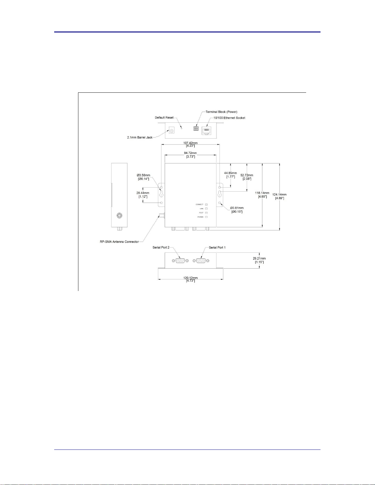
8.0 Mechanical Outline – Industrial Class
Antenna Connector: RP-SMA (Reverse Polarity – SMA)
Requires 2.4GHz/5GHz ISM band antenna, 50 input impedance, RP-SMA
connector
Serial Connector: DB-9M (Male)
Requires DB-9F (Female)
Ethernet Connector: RJ-45 Socket
Requires RJ-45 plug, 10/100 Ethernet interface
Power Connector: 2.1mm Barrel Jack
Requires 2.1mm ID, 5.5mm OD, +5-36 VDC center pin.
Power Connector: Terminal Block (2 connector)
Requires16-30 AWG gauge wire.
1/9/2014 21
Page 22

B&B Electronics, Inc. AirborneM2M™ User Manual
9.0 Getting Started
9.1 Unpack the AirborneM2M™ Device
Unpack the AirborneM2M™ Device and compare the package contents with the
items listed on the front of the included Quick Start Guide. If any item is missing
or damaged, contact B&B immediately.
Contact details can be found at www.bb-elec.com.
Be sure you have the following:
Wireless Access Point
CD with Airborne Command Center Software and User Manual
(2) Antennas.
22 1/9/2014
Page 23
AirborneM2M™ Users Guide B&B Electronics, Inc.
1
Place the AirborneM2M™ CD in the CD/DVD drive of the laptop or desktop you will be using to configure the
AirborneM2M™ device. Follow the on screen directions for installation.
2
Use a piece of Cat5 cable to connect the Ethernet port on the APXx to a network that supports DHCP, or
directly to the Ethernet port on your laptop or desktop.
Note: When connected directly to a computer Ethernet port, disable all other installed Ethernet adapters,
wireless or wired, during configuration process.
3
Apply power to the APXx-Q542x.
The unit will boot and display the following LED patterns:
COMM: RED
LINK : OFF
POST: ORANGE
POWER: BLUE
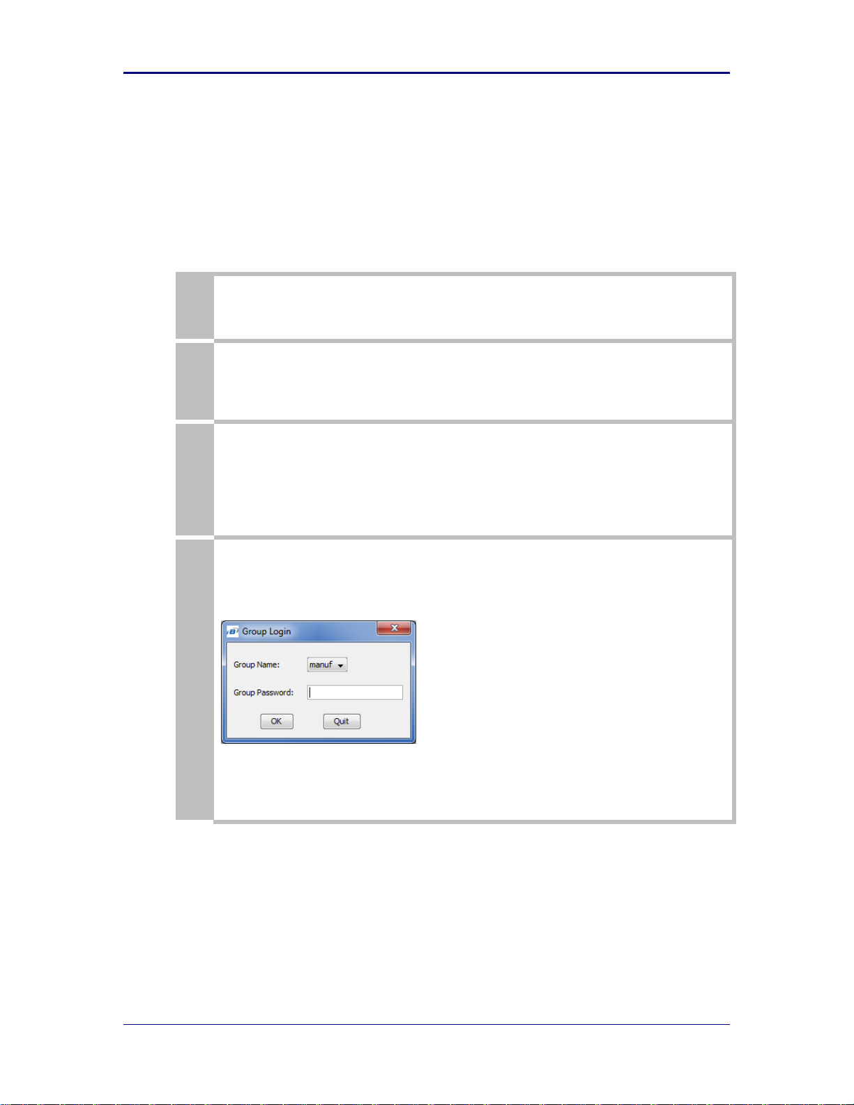
4
Run the Airborne Management Center (AMC) application. This was installed during the CD installation and a
menu item will be found in the Airborne folder located in the programs directory of your system. The
application will display the following dialog:
Select Group Name: manuf and enter Group Password: dpac
10.0 Setup (APXx-Q542x)
The instructions in Table 12 provide a step-by-step guide for configuration of the
AirborneM2M™ Access Point/Wireless Router (APXx-Q542x).
Table 12- APXx Accessing the Web Interface
1/9/2014 23
Page 24
B&B Electronics, Inc. AirborneM2M™ User Manual
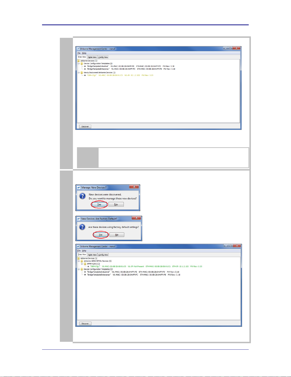
5
The AMC will load and discover the attached device.
Note: You may be required to wait up to 180 seconds before the APXx is discovered and displayed. This is due
to the use of the AutoIP fallback function when connected directly to the APXx.
If the unit is not detected please verify that your firewall is disabled. Run a “Discover”,
if the unit is still not being detected, close down AMC and restart it by doing a Right
Click on the AMC icon and select “Run as administrator”.
6
Manage Your Device
24 1/9/2014
Page 25
AirborneM2M™ Users Guide B&B Electronics, Inc.
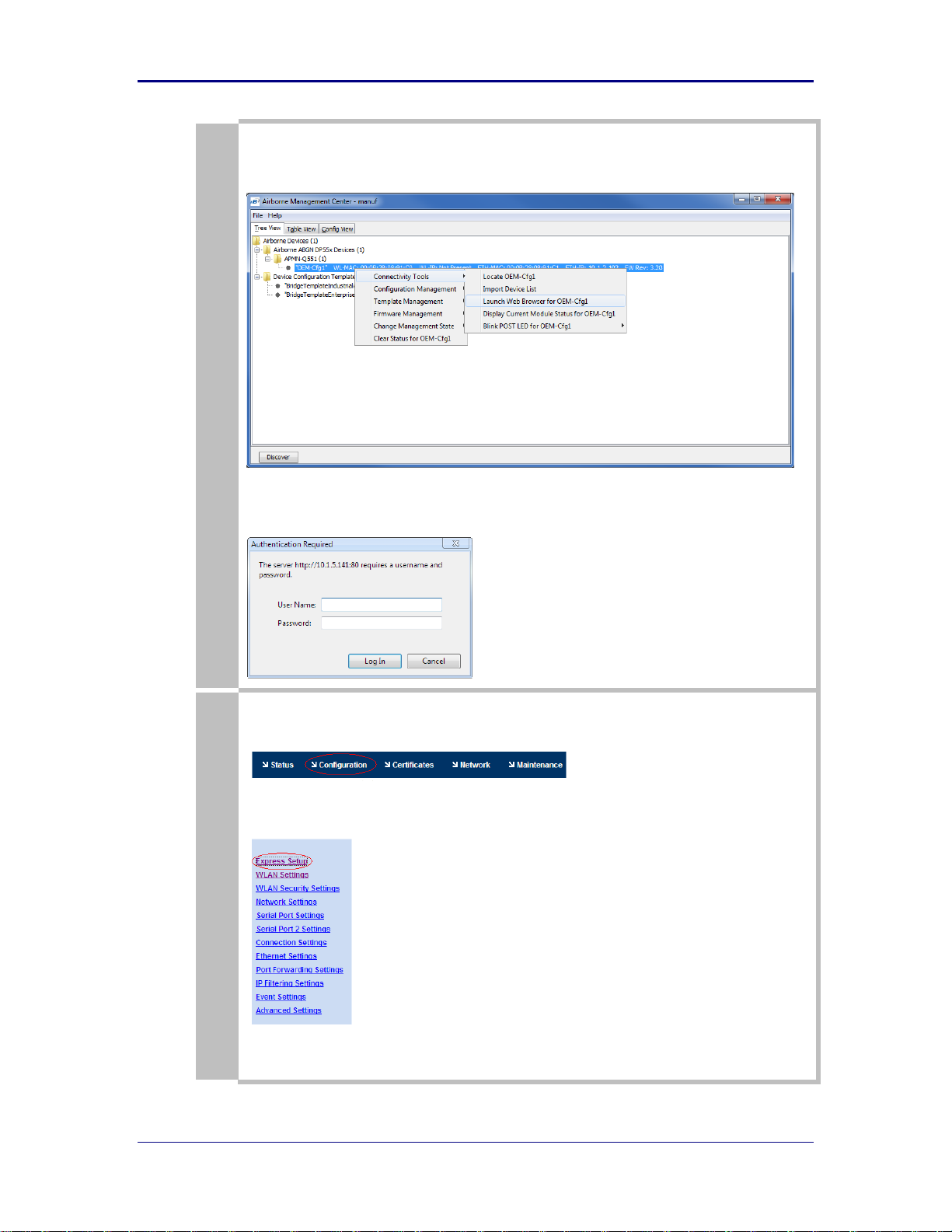
Right Click the device’s name. Under “Connectivity Tools” choose “launch web browser for OEM-Cfg1.” This
will open the device’s browser-based management window.
Username= “dpac”
Password = “dpac”
7
If this is not the first time you have accessed the web interface it will default to the Module Status page. If is
the first time, the web browser will default to the Express setup page. To access the Express Setup Page, select
the Configuration tab the top of the page (dark blue bar).
Then select the Express Setup link in the left hand column (light blue column) You are now ready to configure
your device.
Note that none of your changes will take effect until you click the “Commit” button at the bottom of the page
and then reboot the device.
1/9/2014 25
Page 26
B&B Electronics, Inc. AirborneM2M™ User Manual
8
If your device is connected and configured correctly you will see the following LED status.
COMM: RED
LINK : GREEN
POST: GREEN
POWER: BLUE
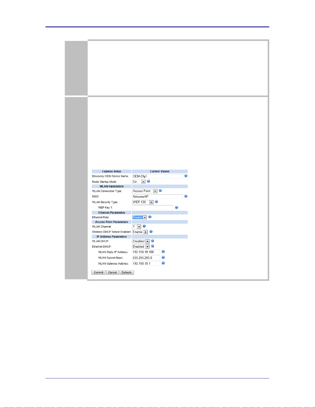
9
Access Point in Router Mode
(Connected wireless devices are set up on their own network)
Discovery OEM Device Name = (Users option)
Radio Startup Mode = On
WLAN Connection Type = Access Point
SSID = (Users option)
WLAN Security Type = (Users option)
Ethernet Role = Router
WLAN Channel: = (Users option)
Wireless DHCP Server Enabled = Enable
WLAN DHCP: (Client) = (Not used)
Ethernet DHCP(for networks with DHCP servers) = Enabled
WLAN Static IP address = 192.168.10.100 (first IP ad dress assigned by WLAN DHCP server.)
WLAN Subnet Mask = 255.255.255.0
WLAN Gateway Address = 192.168.10.1
26 1/9/2014
Page 27
AirborneM2M™ Users Guide B&B Electronics, Inc.
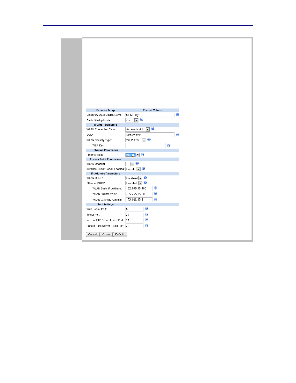
10
Access Point in Bridge Mode
(Connected wireless devices are connected to corporate network)
Discovery OEM Device Name = (Users option)
Radio Startup Mode = On
WLAN Connection Type = Access Point
SSID = (Users option)
WLAN Security Type = (Users option)
Ethernet Role = Bridge
WLAN Channel: = (Users option)
Wireless DHCP Server Enabled = (Not used)
WLAN DHCP: (Client) = (Not used)
Ethernet DHCP (for networks with DHCP servers) = (Users option)
WLAN Static IP address = 192.168.10.100 (Not used in Bridge Mode)
WLAN Subnet Mask = 255.255.255.0 (Not used in Bridge Mode)
WLAN Gateway Address = 192.168.10.1 (Not used in Bridge Mode)
1/9/2014 27
Page 28
B&B Electronics, Inc. AirborneM2M™ User Manual
11.0 Using the Web Interface
AirborneDirect™ Device Servers and Wireless Adapters include a web interface that
provides access to module status, parameter modification and certificate and
configuration file management. To use the web interface follow the steps outlined in
section “Error! Reference source not found" to establish the IP address of the module.
After you know the IP address you can open a web browser and enter the IP address of
the module in the URL window.
The web interface currently supports Internet Explorer v6.0 thru 9.0, Firefox v3.x+, Opera
v9.6+, Chrome v4.0+ and Safari v5.0.5+.
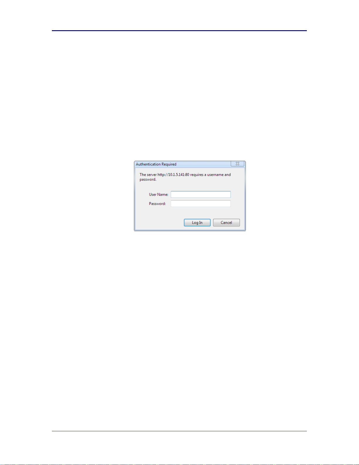
When the authentication request is returned enter username “dpac” and password
“dpac”.
Figure 4 - Website Login
Username: dpac
Password: dpac
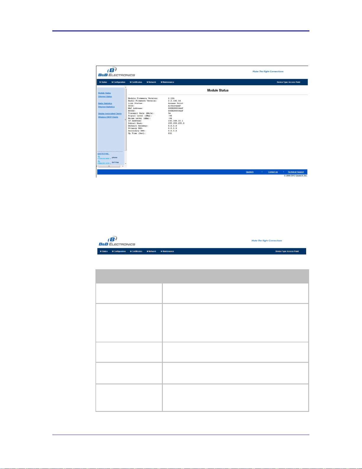
After successfully authenticating with the module, you will be logged into the web server.
If this is the first time you have accessed the device the Express Setup page will be
displayed. See section 12.0 for configuration of the device using this page. If you have
previously configured the device the default home page will be displayed (See Figure
5).From here you can update device settings if required. A quick overview of the web
interface follows.
28 1/9/2014
Page 29
AirborneM2M™ Users Guide B&B Electronics, Inc.
Title
Description
Status
Provides status and performance characteristics for the network
interfaces available. Includes radio statistics and Ethernet
statistics.
Configuration
Allows viewing and configuration of all the interface settings
including wireless LAN, network connectivity, security, FTP client,
serial port and web server.
Includes the interface for delivery of OEM and user configuration
files, as well as management and viewing of current
configurations.
Certificates
This menu item provides the interface for certificate delivery and
management. Included in this section are the abilities to view
resident certificates, upload and delete certificates.
Network
With this section it is possible to locate other Airborne Device
Server modules on the current network.
It is also possible to scan for available Access Points.
Maintenance
This section allows the updating of the modules firmware. You can
also revert the device settings to OEM defaults and restart the
module remotely.
The module locate function is also enabled in this section.
Figure 5 - Default Home Page
11.1 Navigation Bar
Figure 6- Website Navigation Bar
Table 13 - Navigation Bar Items
1/9/2014 29
Page 30
B&B Electronics, Inc. AirborneM2M™ User Manual
11.2 Feature Links
Each Navigation Bar link gives you access to a set of Features/Fields. These are
different for each Navigation option and change for different device selections.
The Feature Links are located in the left hand panel of the web page. (See
Figure 7.)
Figure 7- Feature Links
11.3 Navigating the Website
A standard web page looks like Figure 8. The navigation bar runs along the top
of the page. Page-specific feature links are listed in the left hand pane of the
page. The specific parameters are shown in the main display panel.
Figure 8 - Airborne Web Page
30 1/9/2014
Page 31

AirborneM2M™ Users Guide B&B Electronics, Inc.
Note that the changes to the parameters will not be applied until a module restart
(reboot) has been completed.
To select any of the items, move your cursor over the item and press the lefthand mouse button. The items in the Navigation bar and the Feature Links are
hyperlinks and will cause the mouse cursor to change from an arrow pointer to a
finger pointer when placed over them.
To find out what a specific field does, click on the question mark next to the field.
A help balloon will appear. It will provide details on the function of the field and
its valid range of values.
11.4 Updating a Field
To update a field, select the field by pressing the Left Hand mouse button. Then
either type in the appropriate content or select it from the pull down menu.
Once you have finished modifying parameters, scroll to the bottom of the page
and press the Commit button. The page will then indicate that the changes have
been completed successfully. It will offer you the choice of returning to the
configuration page by pressing the Reload button or restarting the module by
pressing the Reboot button. Changes to the parameters will not be applied until
a module restart (reboot) has been completed.
Before the Commit button has been pressed, all modified fields can be returned
to their original state by pressing the Cancel button.
11.5 Uploading Certificates
Adding certificates to the Airborne Device Server module is very easy when
using the web interface.
Figure 9 - Upload Certificate Web Page
1/9/2014 31
Page 32

B&B Electronics, Inc. AirborneM2M™ User Manual
Step
Description
Navigation Bar
Select Certificates
You will see a list of certificates currently resident on the
module when you enter the Certificate File List window.
Feature Link
Select Upload Certificates
You will see a field for entering the location of the
certificate you want to upload.
Press Browse... Button
This will open a dialog box in which you can locate the
certificate you wish to upload to the module. Select the
Certificate file and press Open.
This will return you to the Certificate Upload window. The
file you have chosen will now be listed next to the
Browse… button.
Press Upload Certificate
You will see a notice that the certificate has been
successfully uploaded to the module.
Press List Certificates Files
This will show the current certificates resident on the
module and will include the file you have just uploaded.
Table 14 - Uploading Certificates
11.6 Upload Configuration Files
The Airborne Device Server module supports both OEM and User configuration
files for provisioning the module. Delivery of these configuration files can be
performed through the web interface. A full description of these files can be found
in the Airborne CLI manual.
To upload configuration files follow the steps in Table 15.
32 1/9/2014
Page 33

AirborneM2M™ Users Guide B&B Electronics, Inc.
Step
Description
Navigation Bar
Select Configuration
You will see major WLAN parameters displayed.
Feature Link
Select Upload Configuration File
The page will present you with a field for entering the
location of the configuration you want to upload, along
with a choice of OEM, User or Encrypted Configuration.
Press Browse... Button
This will open a dialog box in which you can locate the
certificate you wish to upload to the module. Select the
configuration file and press Open.
This will return you to the Configuration Upload window.
The file you have chosen will appear in the field next to
the Browse… button.
Select User or OEM Configuration
This defines the configuration you are installing. OEM
Configurations will survive a factory reset, User will not.
Press Upload Configuration
You will see a notice that the configuration has been
successfully uploaded to the module.
Press List Configuration Files
This will display the current configuration files resident
on the module and will include the file you have just
uploaded.
*
Uploading a configuration file will overwrite any configuration file already stored on
the module. This will cause a change in configuration when a module restart is
performed.
IMPORTANT: Confirm that the OEM or USER settings in the configuration files will
allow the user to communicate with the module after the upload and a restart has
been completed.
Figure 10 - Upload Configuration Web Page
Table 15 - Uploading Configurations
1/9/2014 33
Page 34

B&B Electronics, Inc. AirborneM2M™ User Manual
11.7 Updating Firmware
The module’s firmware may be updated using the web interface. Please refer to
Table 16 for the procedure to do this.
Updating the firmware will not alter any existing configuration files or certificates
loaded on the module.
You can obtain the version of firmware you wish to install from the B&B
Electronics website or B&B Electronics technical support. The firmware will be a
binary image file (.img) and will indicate the version of the firmware in the file
name.
Once you have obtained the firmware, save the firmware file to a location on the
system that you are using to control the module, or at a location that is
accessible to that system. Use the Firmware Update page to locate and upload
the new firmware.
Figure 11 - Firmware Update Page
34 1/9/2014
Page 35

AirborneM2M™ Users Guide B&B Electronics, Inc.
Step
Description
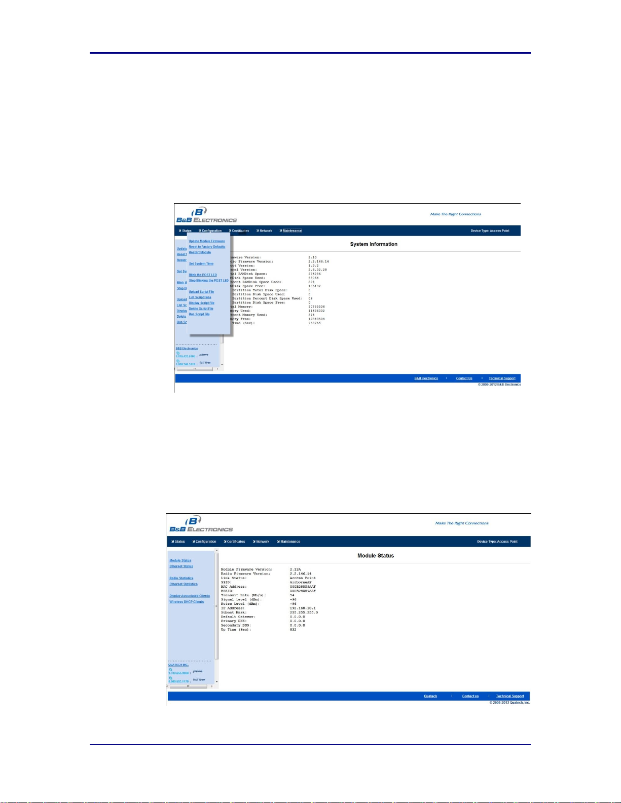
Navigation Bar
Select Maintenance
This will open a window showing the current module
status.
Figure 12 - Firmware Update in Progress
Figure 13 - Firmware Update Complete
When the firmware has been successfully flashed, “Firmware flashing completed
successfully” will appear on screen. Select the Restart button. You may confirm the
change on the Module Status page.
1/9/2014 35
Table 16 - Updating Firmware
Page 36

B&B Electronics, Inc. AirborneM2M™ User Manual
Step
Description
Feature Link
Select Update Module Firmware
The page will present you with a field to enter the
location of the module firmware you want to upload.
The current firmware version number is displayed at the
top of the page.
Press Browse... Button
This will open a dialog box to help you locate the
firmware image that you wish to upload to the module.
Select the firmware image file and press Open.
This will return you to the Upload Firmware window.
The location and file name of the firmware image you
wish to upload will now appear in the field next to the
Browse… button.
Press Load New Firmware
You will then see a notice that the firmware upload has
begun (Error! Reference source not found.).
When the upload has been completed successfully and
the firmware has been updated, a window indicating
this will appear (Error! Reference source not found.).
Press Reboot
This will restart the module and the new firmware will
be loaded.
DO NOT REMOVE POWER FROM THE MODULE DURING THE
FIRMWARE UPDATE.
This may cause the device to become non-operational. If this happens please contact
B&B Electronics Technical Support.
36 1/9/2014
Page 37

AirborneM2M™ Users Guide B&B Electronics, Inc.
Step
Description
Navigation Bar
Select Configuration
You will see a group of fields under the banner of WLAN
Parameters.
Feature Link
Select Express Setup
This step is optional. If this is the first time the device has been
configured this page will automatically be displayed.
12.0 Express Setup Configuration Page
When the device’s web interface is accessed for the first time an Express Setup page will
be shown. This page is designed to allow a quick device setup by presenting the most
popular device configuration options in a single location. For more advanced
configurations the full set of options are available in the feature links (left-hand column).
The Express Setup web page will display the necessary fields based upon the selections
made during configuration. The Express Setup page looks like (Figure 14):
Figure 14 - Express Setup Page
To configure the device for operation each field must be configured correctly. The
following steps should be taken to configure the device (Note: Default settings may hide
certain fields that are not part of default configuration):
Table 17 - Express Page Setup
1/9/2014 37
Page 38

B&B Electronics, Inc. AirborneM2M™ User Manual
Step
Description
Select Discovery OEM Device Name
This parameter allows you to name the device uniquely or
group it into a functional set. When device discovery is used this
name identifies the found device.
If you wanted to uniquely identify the device you could mark it
with a label like Dev1, for example, and then enter Dev1 in this
field. When the device is found it will identify itself as Dev1.
Alternately you could indicate the type of equipment the device
is attached to, like a Haas TL-2 (CNC Turning Center), by giving
the unit a name like Haas_TL_2. When discovered you can then
identify the device you are accessing.
Enter the text string if you wish to change the default value.
This field is optional.
Select Radio Startup Mode
Select On from the drop down menu for the radio to operate.
Select WLAN Connection Type
Default mode is Access Point. To use the device as a wireless
router (default mode) or as an Infrastructure Access Point
(member of an existing wireless network) the connection type
should be Access Point.
Select SSID
Enter the name of the wireless network you wish to setup. This
field is case sensitive and may include spaces.
Select Wireless LAN Security Type
Select the security type you wish to use with your wireless
network.
Depending upon the option you choose you may have to enter
additional information. Once you have selected the security type
the required inputs will be displayed. All displayed fields must
be completed.
If an option is displayed, but grayed out, that option is
unavailable in Access Point mode.
Select Ethernet Role
The default setting is Wireless Router. In this mode devices on
the wired port are assigned static IP addresses or there must be
a DHCP server on the network. A firewall and port forwarding
are available to allow/restrict access between the WLAN and
Ethernet networks.
Change this to Bridge if your application has Ethernet devices
on the wired port. All devices can be on the same subnet and
wireless clients will have access to resources on the wired port.
Select WLAN Channel
This is the channel the Access Point will use to communicate
with clients. It is recommended that you use only one Access
Point per channel.
The default is 1.
Select Wireless DHCP Server Enabled
When Enabled this will provide IP addresses to clients that are
using a DHCP client for IP address assignment. (Router mode)
When the Ethernet port is in Bridge mode, the DHCP server will
provide IP addresses for Ethernet clients also.
Select WLAN DHCP
This parameter is ignored in AP mode.
Select Ethernet DHCP
The function of this field depends upon the Ethernet mode
setting.
If Ethernet mode is Client; enabling this will cause the Ethernet
interface to obtain an IP address from a DHCP on the network
attached to the Ethernet port.
If Ethernet Mode or Bridge is Router; This parameter is
ignored.
38 1/9/2014
Page 39

AirborneM2M™ Users Guide B&B Electronics, Inc.
Step
Description
Select WLAN Static IP
The function of this field depends upon whether or not the
DHCP Server is enabled on the WLAN interface.
If the DHCP Server is disabled, this field defines the static IP
address for the wireless interface.
If the DHCP Server is enabled, this field defines the first IP
address leased by the DHCP server. Addresses are incremented
as new clients are leased addresses.
Default: 192.168.10.100
Select WLAN Subnet Mask
The function of this field depends upon whether or not the
DHCP Server is enabled on the WLAN interface.
If the DHCP Server is disabled, this field defines the subnet
mask used by the wireless interface.
If the DHCP Server is enabled, this field defines the subnet
mask provided by the DHCP server.
Default: 255.255.255.0
Select WLAN Gateway Address
The function of this field depends upon whether or not the
DHCP Server is enabled on the WLAN interface.
If the DHCP Server is disabled, this field defines the gateway
IP address used by the wireless interface.
If the DHCP Server is enabled, this field defines the gateway IP
address provided by the DHCP server.
If the DHCP Server is enabled, this field defines the IP address
of the WLAN interface of the APXx.
Default: 192.168.10.1
Select Ethernet Static IP
The function of this field depends upon whether or not the
Ethernet Mode setting.
If Ethernet Mode is Client, this field defines the IP address to
be used if DHCP is not being used or if DHCP fails.
If Ethernet Mode is Bridge or Router, this field defines the
static IP address to be used by the Ethernet interface.
When the Ethernet Mode is Bridge it is recommended that this
field be set to an IP address within the same subnet as the
WLAN Static IP address.
Default: 192.168.2.100
Select Ethernet Subnet Mask
This field defines the subnet to be used with the Ethernet Static
IP address.
Default: 255.255.255.0
Select Ethernet Gateway Address
This field defines the Gateway IP address to be used by the
Ethernet port.
Default: 0.0.0.0
(Optional) Select Web Server Port
Only displayed when Ethernet Mode is set to Bridge.
Defines the port number used by the device for HTTP access
(web interface).
It is recommended that this be changed from the default 80.
(Optional) Select Telnet Port
Only displayed when Ethernet Mode is set to Bridge.
Defines the port number used by the device for Telnet & TCP/IP
access (CLI interface).
(Optional) Select Internal FTP Server
Listen Port
Only displayed when Ethernet Mode is set to Bridge.
Defines the port number used by the device to listen for FTP
access.
(Optional) Select Secure Shell Server
(SSH) Port
Only displayed when Ethernet Mode is set to Bridge.
Defines the port number used by the device to listen for SSH
access.
Press Commit [Button]
Saves changes to the device.
1/9/2014 39
Page 40

B&B Electronics, Inc. AirborneM2M™ User Manual
Step
Description
Optional
Press Reload [Button]
Reloads the Express Settings page. Select this if you have
further configuration options to change.
Optional
Press Restart [Button]
Restarts the device. After the device is rebooted it will attempt
to authenticate to the configured network. As long as the
network is in range the wireless interface will connect.
If the network is using DHCP an IP address will be assigned to
the WLAN interface and IP connectivity is possible over the
WLAN network.
If the network is using static IP addresses it will be necessary to
configure the network interface. See the next step.
The web interface supports advanced configuration of the device through the additional
pages. The following sections provide guidance on how to use these pages for specific
configurations.
40 1/9/2014
Page 41

AirborneM2M™ Users Guide B&B Electronics, Inc.
13.0 Configuring the Wireless Interface
For configurations other than Access Point please refer to the AirborneDirect™ User
Manual.
1/9/2014 41
Page 42

B&B Electronics, Inc. AirborneM2M™ User Manual
Step
Description
Navigation Bar
Select Configuration
You will see a group of fields under the banner of
WLAN Parameters.
Feature Link
Select WLAN Security Settings
The wireless interface must be configured before
configuring the security for the network.
A page showing the range of security options and
fields is displayed.
Select Wireless LAN Security
Select WEP64 or WEP128 from the drop down list.
The options identify the length of the key that will
be used with the security protocol.
Select Authentication Type
Select Auto from the drop down list. This field
should not need to be changed. Only modify it if you
have been specifically told to do so by the network
administrator.
Select Default WEP Key
Select the default key you wish to use with the AP.
There must be a valid key in the selected key
number field.
Select WEP Key 1 - 4
Select the key field that matches the one selected in
Default WEP Key field.
If WEP64 is selected the key length is 10 digits.
If WEP128 is selected the key length is 26 digits.
More than one key field can be completed.
Press Commit [Button]
Saves changes to the device.
Optional
Press Reload [Button]
Reloads the WLAN Settings page. Select this if you
have further configuration options to change.
Optional
Press Restart [Button]
Restarts the device. After the device has rebooted
WEP security will be applied to the network. Any
client using the network will need to be configured
to match the installed settings.
14.0 Configuring the Security Settings
Almost all 802.11 networks use some sort of security to protect the network from
unauthorized use. There are many types of security options available. The following
section will cover configurations for the most popular options.
14.1 Configuring for WEP Security
Although an old protocol, WEP is still used by many networks. The Airborne
device supports many variations of WEP. However, we will only cover the most
popular in the following table.
Table 18 - Configuring for WEP Security
14.2 Configuring for WPA-PSK Security
This security type is a very popular type and is easy to configure. Most often
used in small office and home environments.
42 1/9/2014
Page 43

AirborneM2M™ Users Guide B&B Electronics, Inc.
Step
Description
Navigation Bar
Select Configuration
You will see a group of fields under the banner
of WLAN Parameters.
Feature Link
Select WLAN Security Settings
The wireless interface must be configured
before configuring the security for the network.
A page showing the range of security options
and fields is displayed.
Select Wireless LAN Security
Select WPA-PSK from the drop down list.
Select WPA Protocol Version
Select Auto from the drop down list. This field
should not need to be changed. Only modify it
if you have been specifically told to do so by
the network administrator.
Select WPA/WPA2 Pre Shared Key (PSK)
Enter the PreShared Key (PSK) you wish to use
on the network. It must be a minimum of eight
characters long.
The PSK cannot include spaces.
Press Commit [Button]
Saves changes to the device.
Optional
Press Reload [Button]
Reloads the WLAN Settings page. Select this
if you have further configuration options to
change.
Optional
Press Restart [Button]
Restarts the device. After the device has
rebooted WPA-PSK security will be applied to
the network. Any client using the network will
need to be configured to match the installed
settings.
Step
Description
Navigation Bar
Select Configuration
You will see a group of fields under the banner
of WLAN Parameters.
Feature Link
Select WLAN Security Settings
The wireless interface must be configured
before configuring the security for the network.
A page showing the range of security options
and fields is displayed.
Select Wireless LAN Security
Select WPA2-PSK from the drop down list.
Select WPA/WPA2 Pre Shared Key (PSK)
Enter the PreShared Key (PSK) you wish to use
with the network.
The PSK cannot include spaces.
Press Commit [Button]
Saves changes to the device.
Optional
Press Reload [Button]
Reloads the WLAN Settings page. Select this
if you have further configuration options to
change.
Table 19 - Configuring for WPA Security
14.3 Configuring for WPA2-PSK Security
This security type is a very popular type and is easy to configure. This provides
the highest level of security available for the APXx in Access Point mode.
Table 20 - Configuring for WPA2 Security
1/9/2014 43
Page 44

B&B Electronics, Inc. AirborneM2M™ User Manual
Step
Description
Optional
Press Restart [Button]
Restarts the device. After the device has
rebooted WPA2-PSK security will be applied to
the network. Any client using the network will
need to be configured to match the installed
settings.
44 1/9/2014
Page 45

AirborneM2M™ Users Guide B&B Electronics, Inc.
Step
Description
Navigation Bar
Select Configuration
You will see a group of fields under the banner
of WLAN Parameters.
Feature Link
Select Connection Settings
The wireless interface and security must be
configured before configuring the Ethernet
settings.
A page is displayed that shows the
configuration options for TCP/IP and UDP
connections to the device. You may configure
Telnet, HTTP and SSH ports on this page.
Select Telnet Port
Enter the port number you wish to use for a
telnet (TCP/IP) connection to the device.
The default 23 should only be changed if your
application requires access to port 23 for
another purpose.
Press Commit [Button]
Saves changes to the device.
Press Reload [Button]
Reloads the Connection Settings page.
Feature Link
Select Serial Port 1 Settings/Serial Port 2
Settings
The wireless interface and security must be
configured before configuring the Ethernet
settings.
Displays a page showing the serial port
configuration. You may set the default mode of
operation for the serial interfaces on this page
Select Serial CLI Default Mode
Select Listen from the drop down menu.
Press Commit [Button]
Saves changes to the device.
Optional
Press Reload [Button]
Reloads the Serial Port Settings page. Select
this if you have further configuration options to
change.
15.0 Configuring the Serial Device Server
The APXx-Q524x can be used as a Serial Device Server even when in Access Point
mode. The following section will cover the full configuration of a Serial Device.
The following section explains how to manually configure the unit to accept TCP/IP
connections and automatically setup a data tunnel with one of the serial ports. The
configuration is independent of the source of the request, as the tunnel ports are
available to both the WLAN and Ethernet interfaces.
Airborne devices support conditional tunnel binding based upon rules included in the
configuration. The major options will be included.
15.1 Configuring Serial Port for Access on Telnet Port
A data tunnel can be made using the device’s telnet port as the network
connection port. This does require authenticating with the device and manually
initiating the tunnel connection. Configuring the device to support this approach is
covered in the following table.
Table 21–Configure Data Tunnel on Telnet Port
1/9/2014 45
Page 46

B&B Electronics, Inc. AirborneM2M™ User Manual
Step
Description
Optional
Press Restart [Button]
Restarts the device. After the device has
rebooted it will attempt to authenticate to the
configured network. As long as the network is
in range the wireless interface will connect.
Once authenticated to the network it is possible
for a TCP/IP connection to be made on the
Telnet port.
Step
Description
Open TCP socket to device
Using the WLAN IP Address and configured
telnet port number.
Authenticate with device
authdpacdpac
Any user level above L5 can authenticate with
the unit.
Device responds OK
Open data tunnel to serial port
pass-x
Where x can be p1, p2 or any.
p1orp2 binds to the indicated serial port, as
long as the serial port is in listen mode and
does not already have a data tunnel open.
Any binds to the first serial port which is in
listen mode and does not already have a data
tunnel open.
Step
Description
Navigation Bar
Select Configuration
You will see a group of fields under the banner
of WLAN Parameters.
Feature Link
Select Connection Settings
The wireless interface and security must be
configured before configuring the Ethernet
settings.
A page appears showing the configuration
options for TCP/IP and UDP connections to the
device. Configuration of Telnet, HTTP and SSH
ports can be done on this page.
Select Tunnel Enabled
Select Enabled.
To establish a data tunnel and gain access to the serial data from the WLAN or
Ethernet interface follow the steps in Table 22.
Table 22 - Data Tunnel using Telnet Port
15.2 Configuring Serial Port 1 for Access on Tunnel Port
A data tunnel can be made using the device’s tunnel port as the network
connection port. This does not require authenticating with the device and
automatically initiates the tunnel connection. Configuring the device to support
this approach is covered in the following table.
46 1/9/2014
Table 23 – Configure Data Tunnel on Serial Port 1 Tunnel Port (TCP)
Page 47

AirborneM2M™ Users Guide B&B Electronics, Inc.
Step
Description
Select Tunnel Port
Enter the port to be used for the tunnel.
Default is 8023. This should only be changed
if a port is already defined for the application
server or it is already being used by another
service.
Select Tunnel Mode
Select TCP from drop down menu.
Press Commit [Button]
Saves changes to the device.
Press Reload [Button]
Reloads the Connection Settings page.
Feature Link
Select Serial Port Settings
The wireless interface and security must be
configured before configuring the Ethernet
settings.
Displays a page showing the serial port
configuration. You will set the default mode of
operation for the serial interface here.
Select Serial CLI Default Mode
Select Listen from the drop down menu.
Press Commit [Button]
Saves changes to the device.
Optional
Press Reload [Button]
Reloads the Serial Port Settings page. Select
this if you have further configuration options to
change.
Optional
Press Restart [Button]
Restarts the device. After the device has
rebooted it will attempt to authenticate to the
configured network. As long as the network is
in range the wireless interface will connect.
After authenticated is completed you will be
able to make a TCP/IP connection on the
Telnet port.
Step
Description
Open TCP socket to device
Using the WLAN IP Address and configured
tunnel port number for Serial Port 1 (Default
8023).
Step
Description
Navigation Bar
Select Configuration
You will see a group of fields under the banner
of WLAN Parameters.
To establish a data tunnel and gain access to the serial data from the WLAN or
Ethernet interface follow the steps in Table 24.
15.3 Configuring Serial Port 2 for Access on Tunnel Port
A data tunnel can be made using the device’s tunnel port as the network
connection port. This does not require authenticating with the device and
automatically initiates the tunnel connection. Configuring the device to support
this approach is covered in the following table.
1/9/2014 47
Table 24 - Data Tunnel using Tunnel Port on Serial Port 1
Table 25 – Configure Data Tunnel on Serial Port 2 Tunnel Port (TCP)
Page 48

B&B Electronics, Inc. AirborneM2M™ User Manual
Step
Description
Feature Link
Select Connection Settings
The wireless interface and security must be
configured before configuring the Ethernet
settings.
A page showing the configuration options for
TCP/IP and UDP connections to the device.
Configuration of Telnet, HTTP and SSH ports is
possible through this page.
Select Tunnel Enabled – Serial Port 2
Select Enabled.
Select Tunnel Port – Serial Port 2
Enter the port to be used for the tunnel.
Default is 8024, this should only be changed if
a port is already defined for the application
server or it is already being used by another
service.
Select Tunnel Mode – Serial Port 2
Select TCP from drop down menu.
Press Commit [Button]
Saves changes to the device.
Press Reload [Button]
Reloads the Connection Settings page.
Feature Link
Select Serial Port 2 Settings
The wireless interface and security must be
configured before configuring the Ethernet
settings.
Displays a page showing the serial port
configuration, setting the default mode of
operation for the serial interface is done in this
page.
Select Serial CLI Default Mode
Select Listen from the drop down menu.
Press Commit [Button]
Saves changes to the device.
Optional
Press Reload [Button]
Reloads the Serial Port 2 Settings page.
Select this if you have further configuration
options to change.
Optional
Press Restart [Button]
Restarts the device. After the device has
rebooted it will attempt to authenticate to the
configured network. As long as the network is
in range the wireless interface will connect.
Once authenticated the network it is possible
for a TCP/IP connection to be made on the
Telnet port.
Step
Description
Open TCP socket to device
Using the WLAN IP Address and configured
tunnel port number for Serial Port 2 (Default
8024).
To establish a data tunnel and gain access to the serial data from the WLAN or
Ethernet interface follow the steps in Table 26.
15.4 Configuring Serial Port 1 as TCP Client
In this mode the device will attempt to initiate a TCP connection to a network
based server and establish a data tunnel with Serial Port 1 on a successful
48 1/9/2014
network connection.
Table 26 - Data Tunnel using Tunnel Port on Serial Port 2
Page 49

AirborneM2M™ Users Guide B&B Electronics, Inc.
Step
Description
Navigation Bar
Select Configuration
You will see a group of fields under the
banner of WLAN Parameters.
Feature Link
Select Connection Settings
The wireless interface and security must be
configured before configuring the Ethernet
settings.
You will see a page showing the
configuration options for TCP/IP and UDP
connections to the device. You may
configure Telnet, HTTP and SSH ports on
this page.
Select TCP Port
Enter the port on which the target server is
listening for TCP connections.
Select TCP Timeout
Enter the inactivity timeout in seconds, after
which the device will close the open data
tunnel on Serial Port 1.
The default 0 disables the timeout.
Select TCP Retry Time
Enter the period(in seconds)that the device
should use to retry establishing the TCP
connection to the target server.
Select Primary TCP Target Server IP Address
Enter the IP address of the primary target
server.
The address must be in the format:
XXX.XXX.XXX.XXX
Optional
Select Secondary TCP Target Server IP
Address
Enter the IP address of the secondary target
server.
The address must be in the format:
XXX.XXX.XXX.XXX
This address will be used if the initial
attempts to connect to the primary server
fail. This field is optional.
Press Commit [Button]
Saves changes to the device.
Press Reload [Button]
Reloads the Connection Settings page.
Feature Link
Select Serial Port 1 Settings
The wireless interface and security must be
configured before configuring the Ethernet
settings.
You will see a page showing the serial port
configuration. You may set the default
mode of operation for the serial interface on
this page.
Select Serial CLI Default Mode
Select Pass from the drop down menu.
Press Commit [Button]
Saves changes to the device.
Optional
Press Reload [Button]
Reloads the Serial Port 1 Settings page.
Select this if you wish to change additional
configuration options.
Table 27 - Configure Serial Port 1 as TCP Client
1/9/2014 49
Page 50

B&B Electronics, Inc. AirborneM2M™ User Manual
Step
Description
Optional
Press Restart [Button]
Restarts the device. After the device has
rebooted it will attempt to authenticate to
the configured network. As long as the
network is in range the wireless interface will
connect.
Once authenticated to the network the
device will attempt to make a TCP
connection with primary target server, using
the configured port number.
Step
Description
Navigation Bar
Select Configuration
You will see a group of fields under the
banner of WLAN Parameters.
Feature Link
Select Connection Settings
The wireless interface and security must be
configured before configuring the Ethernet
settings.
You will see a page showing the
configuration options for TCP/IP and UDP
connections to the device. You may
configure Telnet, HTTP and SSH ports on
this page.
Select TCP Port – Serial Port 2
Enter the port on which the target server is
listening for TCP connections.
Select TCP Timeout – Serial Port 2
Enter the inactivity timeout in seconds, after
which the device will close the open data
tunnel on Serial Port 1.
The default 0 disables the timeout.
Select TCP Retry Time – Serial Port 2
Enter the period (in seconds) the device
should use to retry establishing the TCP
connection to the target server.
Select Primary TCP Target Server IP Address
– Serial Port 2
Enter the IP address of the primary target
server.
The address must be in the format:
XXX.XXX.XXX.XXX
Optional
Select Secondary TCP Target Server IP
Address – Serial Port 2
Enter the IP address of the secondary target
server.
The address must be in the format:
XXX.XXX.XXX.XXX
This address will be used if the initial
attempts to connect to the primary server
fail. This field is optional.
Press Commit [Button]
Saves changes to the device.
Press Reload [Button]
Reloads the Connection Settings page.
15.5 Configuring Serial Port 2 as TCP Client
In this mode the device will attempt to initiate a TCP connection to a network
based server and establish a data tunnel with Serial Port 2 on a successful
network connection.
Table 28 - Configure Serial Port 2 as TCP Client
50 1/9/2014
Page 51

AirborneM2M™ Users Guide B&B Electronics, Inc.
Step
Description
Feature Link
Select Serial Port 2 Settings
The wireless interface and security must be
configured before configuring the Ethernet
settings.
You will see a page showing the serial port
configuration. You may set the default
mode of operation for the serial interface on
this page.
Select Serial CLI Default Mode
Select Pass from the drop down menu.
Press Commit [Button]
Saves changes to the device.
Optional
Press Reload [Button]
Reloads the Serial Port 2 Settings page.
Select this if you wish to change additional
configuration options.
Optional
Press Restart [Button]
Restarts the device. After the device has
rebooted it will attempt to authenticate to
the configured network. As long as the
network is in range the wireless interface will
connect.
Once authenticated to the network the
device will attempt to make a TCP
connection with primary target server, using
the configured port number.
1/9/2014 51
Page 52

B&B Electronics, Inc. AirborneM2M™ User Manual
16.0 Web Page Overview
The following section highlights the contents of each web page and provides a reference
to the associated CLI command. For further explanation of each of the fields please refer
to the referenced command in the table (See Airborne Enterprise Command Line
Reference Manual). When using CLI command, typing a command followed by a space
and a ‘?’ will display help for the command (e.g. “wl-type ?”).
52 1/9/2014
Page 53

AirborneM2M™ Users Guide B&B Electronics, Inc.
URL
/Status/Module Status
Description
When authenticated to the Airborne device, this page provides important information about the
device’s firmware version, wireless connection status and wireless interface network configuration.
Field
CLI Command
Displayed Page
wl-info
Module Status
1/9/2014 53
Page 54

B&B Electronics, Inc. AirborneM2M™ User Manual
URL
/Status/Ethernet Status
Description
Provides important information about the device’s firmware version, Ethernet connection status and
Ethernet interface network configuration.
Field
CLI Command
Displayed Page
eth-info
Ethernet Status
54 1/9/2014
Page 55

AirborneM2M™ Users Guide B&B Electronics, Inc.
URL
/Status/Radio Statistics
Description
Provides information about the packet transmit and receive performance of the wireless interface.
Field
CLI Command
Displayed Page
stats<blank> or radio
Radio Statistics
1/9/2014 55
Page 56

B&B Electronics, Inc. AirborneM2M™ User Manual
URL
/Status/Ethernet Statistics
Description
Provides information about the packet transmit and receive performance of the Ethernet interface.
Field
CLI Command
Displayed Page
statsethernet
Ethernet Statistics
56 1/9/2014
Page 57

AirborneM2M™ Users Guide B&B Electronics, Inc.
URL
/Status/Display Associated Clients
Description
Displays associated clients.
Field
CLI Command
Displayed Page
eth-clients
Display Associated Clients
1/9/2014 57
Page 58

B&B Electronics, Inc. AirborneM2M™ User Manual
URL
/Status/Wireless DHCP Clients
Description
Displays wireless DHCP clients.
Field
CLI Command
Displayed Page
eth-dhcp-clients
Wireless DHCP Clients
58 1/9/2014
Page 59

AirborneM2M™ Users Guide B&B Electronics, Inc.
URL
/Configuration/Express Setup
Description
Provides a simplified configuration option set in a single page. This will be the default home page when
configuring the device for the first time, or after a factory reset has been performed.
Field
CLI Command
Discovery OEM Device Name
name-oem
Radio Startup Mode
radio-on, radio-off
Wireless LAN Connection Type
wl-type
SSID
wl-ssid
Wireless LAN Security Type
wl-security
WEP Key 1
wl-key-1
WPA/WPA2Pre Shared Key (PSK)
pw-wpa-psk
Ethernet Role
eth-role
WLAN Channel
wl-chan
Wireless DHCP Server Enabled
wl-dhcp-server
WLAN DHCP
wl-dhcp
Ethernet DHCP
eth-dhcp
WLAN Static IP Address
wl-ip
WLAN Subnet Mask
wl-subnet
WLAN Gateway Address
wl-gateway
Ethernet Static IP Address
eth-ip
Ethernet Subnet Mask
eth-subnet
Ethernet gateway Address
eth-gateway
Web Server Port
wl-http-port
Telnet Port
wl-telnet-port
Internal FTP Server Listen Port
ftp-server-listen-port
Secure Shell Server (SSH) Port
wl-ssh-port
Express Setup
1/9/2014 59
Page 60

B&B Electronics, Inc. AirborneM2M™ User Manual
URL
/Configuration/WLAN Settings
Description
Configures the wireless interface settings, including network name and type.
Field
CLI Command
Radio Startup Mode
radio-on, radio-off
Wireless LAN Connection Type
wl-type
SSID
wl-ssid
Wireless LAN Channel
wl-chan
WLAN TX Power (dBm)
wl-tx-power
WLAN Beacon Interval
wl-beacon-int
WLAN DTIM Interval
wl-dtim-int
Hide SSID in Beacon
wl-hide-ssid
Access Control Policy
wl-acl-policy
Access Control Policy MAC Addresses
wl-acl-mac
AP-Mode Default Data Rates
wl-mode
Wireless DHCP Server Enabled
wl-dhcp-server
Wireless LAN Region
wl-region
WLAN Settings
60 1/9/2014
Page 61

AirborneM2M™ Users Guide B&B Electronics, Inc.
URL
/Configuration/WLAN Security Settings
Description
Configures the security settings for the target network.
Field
CLI Command
Wireless LAN Security Type
wl-security
Authentication Type
wl-auth
Default WEP Key
wl-def-key
WEP Key 1 - 4
wl-key-1, wl-key-2, wl-key-3, wl-key-4
WPA/WPA2 Pre Shared Key (PSK)
pw-wpa-psk
WLAN Security Settings
1/9/2014 61
Page 62

B&B Electronics, Inc. AirborneM2M™ User Manual
URL
/Configuration/Network Settings
Description
Configures the wireless and Ethernet interface network settings including DHCP, static IP and Fallback
configurations.
Field
CLI Command
WLAN DHCP
wl-dhcp
WLAN DHCP Client Name
wl-dhcp-client
WLAN Static IP Address
wl-ip
WLAN Subnet Mask
wl-subnet
WLAN Gateway IP Address
wl-gateway
Ethernet DHCP
eth-dhcp
Ethernet DHCP Client Name
eth-dhcp-client
Ethernet Static IP Address
eth-ip
Ethernet Subnet Mask
eth-subnet
Ethernet Gateway IP Address
eth-gateway
DNS Server1/2 IP Address
dns-server1, dns-server2
WINS Server 1/2 IP Address
wins-server1, wins-server2
Network Settings
62 1/9/2014
Page 63

AirborneM2M™ Users Guide B&B Electronics, Inc.
URL
/Configuration/Serial Port Settings
Description
Configures the serial port settings on the primary serial port.
Field
CLI Command
Serial CLI Default Mode
serial-default, serial-default-p1
Serial Port Bit Rate
bit-rate, bit-rate-p1
Parity
parity, parity-p1
Data Bits
data-bits, data-bits-p1
Stop Bits
stop-bit, stop-bit-p1
Flow Control
flow, flow-p1
Serial Assert
serial-assert, serial-assert-p1
Input Buffer Flush Size
input-size, input-size-p1
Serial Escape Mode
esc-mode-serial, esc-mode-serial-p1
Network CLI Escape Mode
esc-mode-lan, esc-mode-lan-p1
Escape String
esc-str, esc-str-p1
Serial Interface Type
intf-type
Serial Port Settings
1/9/2014 63
Page 64

B&B Electronics, Inc. AirborneM2M™ User Manual
URL
/Configuration/Serial Port 2 Settings
Description
Configures the serial port settings on the secondary serial port.
Field
CLI Command
Serial CLI Default Mode
serial-default-p2
Serial Port Bit Rate
bit-rate-p2
Parity
parity-p2
Data Bits
data-bits-p2
Stop Bits
stop-bit-p2
Flow Control
flow-p2
Serial Assert
serial-assert-p2
Input Buffer Flush Size
input-size-p2
Serial Escape Mode
esc-mode-serial-p2
Wireless LAN CLI Escape Mode
esc-mode-lan-p2
Escape String
esc-str-p2
Serial Interface Type
intf-type
Serial port 2 cannot run in RS-485 mode and will assume RS-422 mode even if it is set
to RS-485 mode. Serial port 2 cannot run half duplex and must have a 4 wire
connection.
Serial Port 2 Settings
64 1/9/2014
Page 65

AirborneM2M™ Users Guide B&B Electronics, Inc.
URL
/Configuration/Connection Settings
Description
Configures the data tunnel and network port settings for both serial ports. Includes management of
port access and service availability.
Field
CLI Command
Outbound Transmit Type
wl-xmit-type, wl-xmit-type-p1
Primary TCP Target Server IP Address
wl-tcp-ip, wl-tcp-ip-p1
Secondary TCP Target Server IP Address
wl-tcp-ip2, wl-tcp-ip2-p1
TCP Port
wl-tcp-port, wl-tcp-port-p1
TCP Timeout
wl-tcp-timeout, wl-tcp-timeout-p1
TCP Retry Time
wl-retry-time, wl-retry-time-p1
Tunnel Enabled
wl-tunnel, wl-tunnel-p1
UDP Target Server IP Address
wl-udp-ip, wl-udp-ip-p1
UDP Port
wl-udp-port, wl-udp-port-p1
UDP Receive Port
wl-udp-rxport, wl-udp-rxport-p1
UDP Transmit Mode
wl-udp-xmit, wl-udp-xmit-p1
Outbound Transmit Type – Serial Port 2
wl-xmit-type-p2
Primary TCP Target Server IP Address – Serial Port 2
wl-tcp-ip-p2
Secondary TCP Target Server IP Address – Serial Port 2
wl-tcp-ip2-p2
TCP Port – Serial Port 2
wl-tcp-port-p2
TCP Timeout – Serial Port 2
wl-tcp-timeout-p2
Connection Settings
1/9/2014 65
Page 66

B&B Electronics, Inc. AirborneM2M™ User Manual
TCP Retry Time – Serial Port 2
wl-retry-time-p2
Tunnel Enabled – Serial Port 2
wl-tunnel-p2
UDP Target Server IP Address – Serial Port 2
wl-udp-ip-p2
UDP Port – Serial Port 2
wl-udp-port-p2
UDP Receive Port – Serial Port 2
wl-udp-rxport-p2
UDP Transmit Mode – Serial Port 2
wl-udp-xmit-p2
HTTP Port Accessible via Wireless
http-port
Web Server Port
wl-http-port
Default Web Page
<index.html>
Telnet Port Accessible via Wireless
telnet-port
Telnet Port
wl-telnet-port
Telnet Timeout
wl-telnet-timeout
Internal FTP Server Port
ftp-server-port
Internal FTP Server Listen Port
ftp-server-listen-port
SSH Port Accessible via Wireless
ssh-port
Secure Shell Server Port
wl-ssh-port
Connect LED Mode
wl-con-led
TCP Max Retries
tcp-retries
Wireless UDAP Discovery Enabled
wl-udap
Ethernet UDAP Discovery Enabled
eth-udap
66 1/9/2014
Page 67

AirborneM2M™ Users Guide B&B Electronics, Inc.
URL
/Configuration/Ethernet Settings
Description
Configures the Ethernet interface for AirborneDirect™ Ethernet devices.
Field
CLI Command
Ethernet Role
eth-role
DHCP Server Enabled
eth-dhcp-server
MAC Cloning
wl-mac-clone
Ethernet Port Speed/Duplex
eth-mode
Ethernet Settings
1/9/2014 67
Page 68

B&B Electronics, Inc. AirborneM2M™ User Manual
URL
/Configuration/Event Settings
Description
Event Settings
Field
CLI Command
TBD
Event Settings
68 1/9/2014
Page 69

AirborneM2M™ Users Guide B&B Electronics, Inc.
URL
/Configuration/Port Forwarding Settings
Description
Configures port forwarding.
Field
CLI Command
Port Forwarding Default
wl-route-default
Port Forwarding Rule
wl-route
Port Forwarding Settings
1/9/2014 69
Page 70
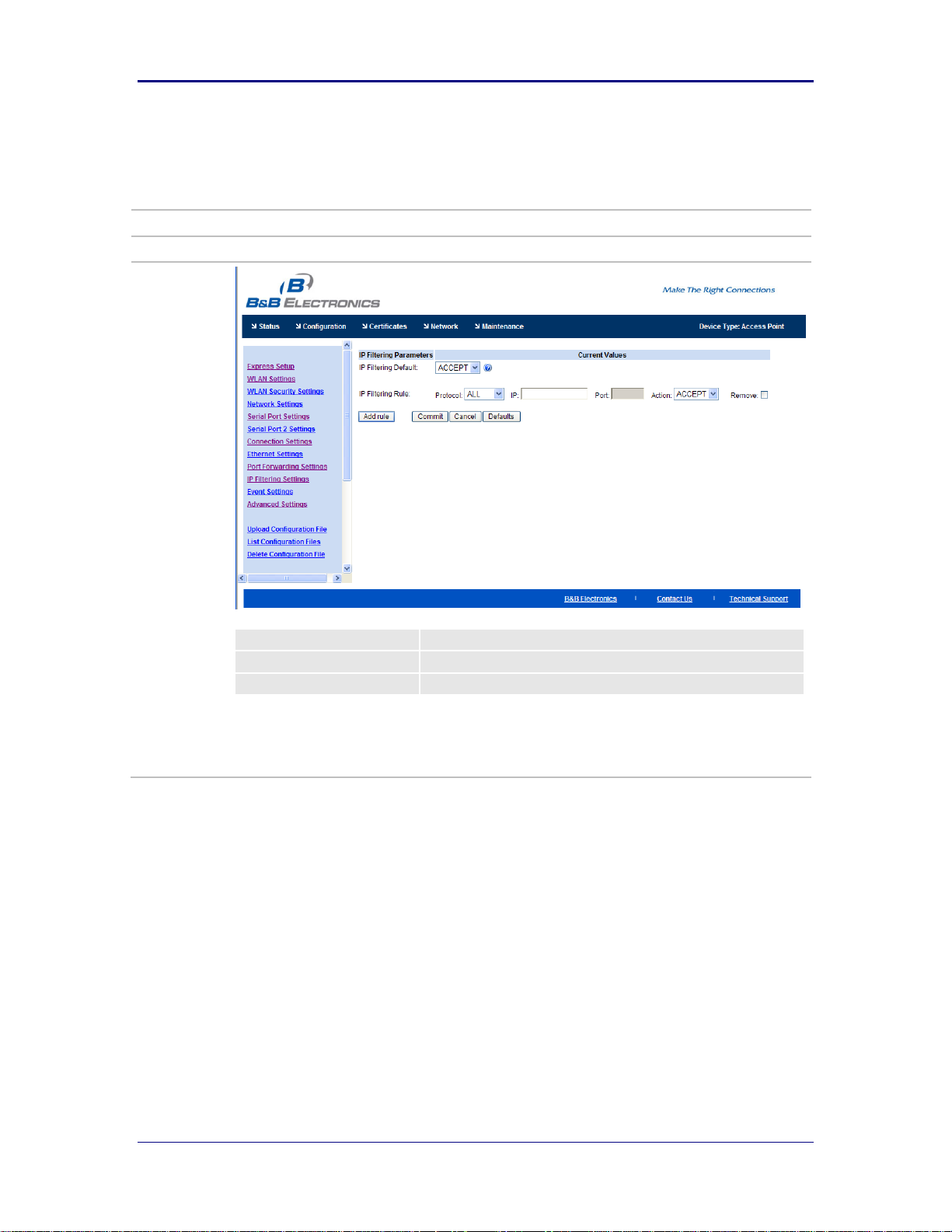
B&B Electronics, Inc. AirborneM2M™ User Manual
URL
/Configuration/IP Filtering Settings
Description
Configures IP filtering.
Field
CLI Command
IP Filtering Default
eth-route-default
IP Filtering Rule
eth-route
IP Filtering Settings
70 1/9/2014
Page 71

AirborneM2M™ Users Guide B&B Electronics, Inc.
URL
/Configuration/Advanced Settings
Description
Configures the advanced configuration settings for the unit, including authentication usernames and
passwords, configuration of SSH, power save setup, GPIO, indicator LED and FTP settings.
Advanced Settings
1/9/2014 71
Page 72

B&B Electronics, Inc. AirborneM2M™ User Manual
72 1/9/2014
Page 73

AirborneM2M™ Users Guide B&B Electronics, Inc.
Field
CLI Command
OEM Defined Version String
oemstr
Device Manufacture Discovery Name
name-manuf
Device OEM Discovery Name
name-oem
Discovery Device Name
name-device
Administrator Password
pw-root
Manufacturing User Name
pw-manuf
Manufacturing Password
user-manuf
OEM User Name
pw-oem
OEM Password
user-oem
CFG User Name
pw-cfg
CFG Password
user-cfg
Regular User Name
pw
Regular User Password
user
Encrypt Wireless Keys
cfg-encrypt
Protect the OEM Configuration
cfg-oem-protect
Minimum Authorization Level for Reset
auth-level reset
Minimum Authorization Level for Radio off
auth-level radio-off
Minimum Authorization Level for Radio on
auth-level radio-on
SSH Default User Name
ssh-default-user
SSH Default Password
ssh-default-password
SSH Key Size (evenly divisible by 8)
ssh-keysize
Module Power Save Mode
pm-mode
Serial Port 1 Inactivity Timeout
wl-tcp-timeout
Serial Port 2 Inactivity Timeout
wl-tcp-timeout-p2
Radio Startup Mode
radio-startup
FTP Server IP Address or Name
ftp-server-ip-address
FTP User Name
ftp-user
FTP Password
ftp-password
FTP Server Path
ftp-server-path
FTP File Name
ftp-server-filename
Timezone Name
timezone-name
Timezone Offset
timezone-offset
Daylight Savings Adjustment
daylight-saving-time
Daylight Savings Time Name
daylight-saving-name
Daylight Savings Time Offset
daylight-saving-offset
Daylight Savings Time Starting Week
daylight-saving-startweek
Daylight Savings Time Starting Day
daylight-saving-startday
Daylight Savings Time Starting Month
daylight-saving-startmonth
Daylight Savings Time Ending Week
daylight-saving-stopweek
Daylight Savings Time Ending Day
daylight-saving-stopday
Daylight Savings Time Ending Month
daylight-saving-stopmonth
NTP Server IP Address or Name
ntp-server-address
NTP Sync at Startup
ntp-startup-sync
NTP Refresh Interval
ntp-refresh-interval
1/9/2014 73
Page 74

B&B Electronics, Inc. AirborneM2M™ User Manual
Antenna Mode
wl-ant
Speedlink Roaming
speedlink
Beacons Missed Before Roaming
wl-beacons-missed
Association Retry Count
wl-assoc-retries
Association Backoff Time (ms)
wl-assoc-backoff
ARP Staleout Time
arp-staleout-time
ARP Reachable Time
arp-reachable-time
Use Directed Probes
wl-specific-scan
Lost Association Link Timeout
wl-link-timeout
Startup Message Mode
startup-msg
Startup Message Text
startup-text
WLAN DHCP Vendor Class ID String
wl-dhcp-vendorid
Ethernet DHCP Vendor Class ID String
eth-dhcp-vendorid
I/O Port F Bit Direction
io-dir-f
I/O Port F Bit Internal Pullup Resistor
io-pullup-f
I/O Port G Bit Direction
io-dir-g
I/O Port G Bit Internal Pullup Resistor
io-pullup-g
Enable LED Signal Strength Meter
led-mode
Enable POST LED
post-led
Enable RF_LINK LED
rf-link-led
Enable WLN_CFG LED
wln-cfg-led
Enable CONN LED
conn-led
Enable Echo for Telnet Sessions
telnet-echo
UDP Server Ping
udp-ping
74 1/9/2014
Page 75

AirborneM2M™ Users Guide B&B Electronics, Inc.
URL
/Configuration/Upload Configuration File
Description
Allows user, OEM or encrypted configuration files to be uploaded to the device.
Field
CLI Command
Upload Configuration [button]
put-cfg
User Config
put-cfg user_config.txt
Encrypted Configuration
put-cfguser_enc_config.uue
OEM Configuration
put-cfg oem_config.txt
Upload Configuration File
1/9/2014 75
Page 76

B&B Electronics, Inc. AirborneM2M™ User Manual
URL
/Configuration/List Configuration File
Description
Displays a list of the configuration files saved to the device.
Field
CLI Command
Displayed Page
list-cfg
List Configuration File
76 1/9/2014
Page 77

AirborneM2M™ Users Guide B&B Electronics, Inc.
URL
/Configuration/Delete Configuration File
Description
Lets you delete previously saved configuration files.
Field
CLI Command
Delete File [Button]
del-cfg
Delete Configuration File
1/9/2014 77
Page 78

B&B Electronics, Inc. AirborneM2M™ User Manual
URL
/Configuration/Active Configuration
Description
Displays the current configuration settings.
Field
CLI Command
Displayed Page
cfg-dump active
Active Configuration
78 1/9/2014
Page 79

AirborneM2M™ Users Guide B&B Electronics, Inc.
URL
/Configuration/User Configuration
Description
Displays the contents of the user_config.txt configuration file.
Field
CLI Command
Displayed Page
cfg-dump user
User Configuration
1/9/2014 79
Page 80

B&B Electronics, Inc. AirborneM2M™ User Manual
URL
/Configuration/OEM Configuration
Description
Displays the contents of the oem_config.txt configuration file.
Field
CLI Command
Displayed Page
cfg-dump oem
OEM Configuration
80 1/9/2014
Page 81

AirborneM2M™ Users Guide B&B Electronics, Inc.
URL
/Configuration/Factory Configuration
Description
Displays the factory configuration settings. These are the default settings delivered from the B&B
Electronics factory.
Field
CLI Command
Displayed Page
cfg-dump factory
Factory Configuration
1/9/2014 81
Page 82

B&B Electronics, Inc. AirborneM2M™ User Manual
URL
/Configuration/WPA Configuration
Description
Displays the current security configuration settings being used by the device.
Field
CLI Command
Displayed Page
cfg-dump wpa
WPA Configuration
82 1/9/2014
Page 83

AirborneM2M™ Users Guide B&B Electronics, Inc.
URL
/Certificates/List Certificates
Description
Displays a list of the certificates saved to the device. This is the home page for the Certificates link.
Field
CLI Command
Displayed Page
list-cert
List Certificates
1/9/2014 83
Page 84

B&B Electronics, Inc. AirborneM2M™ User Manual
URL
/Certificates/Upload Certificate
Description
Lets you upload certificates and private keys to the device.
Field
CLI Command
Upload Certificate [Button]
put-cert
Upload Certificate
84 1/9/2014
Page 85

AirborneM2M™ Users Guide B&B Electronics, Inc.
URL
/Certificates/Delete Certificate
Description
Allows you to delete certificates stored on the device.
Field
CLI Command
Delete Certificate [Button]
del-cert
Delete Certificate
1/9/2014 85
Page 86

B&B Electronics, Inc. AirborneM2M™ User Manual
URL
/Network
Description
Home page for the network-related pages.
Field
CLI Command
Displayed Page
wl-info
Network (Home Page)
86 1/9/2014
Page 87

AirborneM2M™ Users Guide B&B Electronics, Inc.
URL
/Network/Discover Airborne Modules
Description
Displays a list of Airborne devices that are visible to the device on the current network, with IP
address, device type and wireless or Ethernet MAC address.
Field
CLI Command
Displayed Page
discover
Discover Airborne Modules
1/9/2014 87
Page 88

B&B Electronics, Inc. AirborneM2M™ User Manual
URL
/Network/Scan for Access Points
Description
Displays a list of wireless networks within range of the device
Field
CLI Command
Displayed Page
wl-scan
Scan for Access Points
88 1/9/2014
Page 89
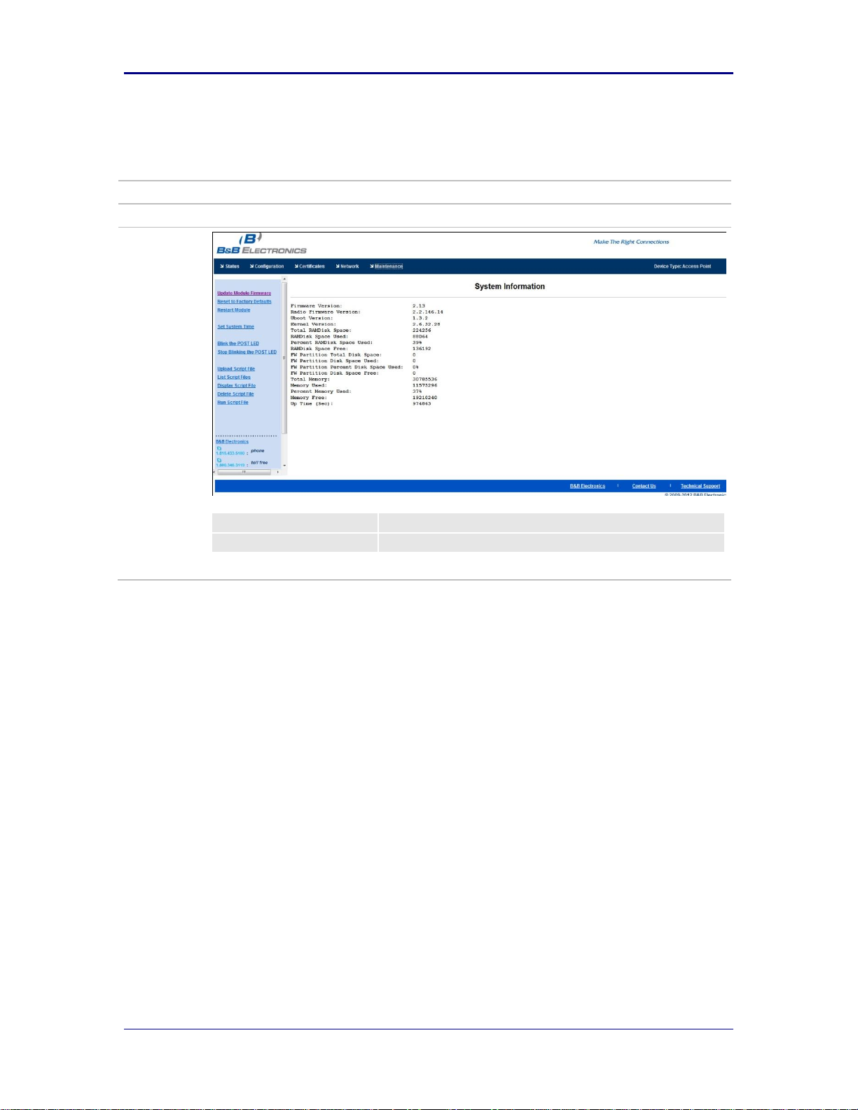
AirborneM2M™ Users Guide B&B Electronics, Inc.
URL
/Maintenance
Description
Home page for the maintenance-related pages.
Field
CLI Command
Displayed Page
sys-info
Maintenance (Home Page)
1/9/2014 89
Page 90

B&B Electronics, Inc. AirborneM2M™ User Manual
URL
/Maintenance/Update Module Firmware
Description
Enables you to update module firmware.
Field
CLI Command
Load New Firmware [Button]
update
Update Module Firmware
90 1/9/2014
Page 91

AirborneM2M™ Users Guide B&B Electronics, Inc.
URL
/Maintenance/Reset Factory Defaults
Description
Returns device to factory defaults. If oem_config.txt is present this will take precedence over the
factory configuration.
Field
CLI Command
Yes [Button]
reset
Reset Factory Defaults
1/9/2014 91
Page 92

B&B Electronics, Inc. AirborneM2M™ User Manual
URL
/Maintenance/Restart Module
Description
Restarts device.
Field
CLI Command
Yes [Button]
restart
Restart Module
92 1/9/2014
Page 93

AirborneM2M™ Users Guide B&B Electronics, Inc.
URL
/Maintenance/Set System Time
Description
Sets system time.
Field
CLI Command
Set System Time
sys-time
Set System Time
1/9/2014 93
Page 94

B&B Electronics, Inc. AirborneM2M™ User Manual
URL
/Maintenance/Blink the POST LED
Description
Makes the POST LED blink. This lets you identify the specific device with which you are communicating.
Field
CLI Command
Displayed Page
blink-post-led on
Blink the POST LED
94 1/9/2014
Page 95

AirborneM2M™ Users Guide B&B Electronics, Inc.
URL
/Maintenance/Stop Blinking the POST LED
Description
Stops the POST LED blinking.
Field
CLI Command
Displayed Page
blink-post-led off
Stop Blinking the POST LED
1/9/2014 95
Page 96

B&B Electronics, Inc. AirborneM2M™ User Manual
URL
/Maintenance/Upload Script Files
Description
Upload Script Files.
Field
CLI Command
Upload Script Files
96 1/9/2014
Page 97

AirborneM2M™ Users Guide B&B Electronics, Inc.
URL
/Maintenance/List Script Files
Description
Lists script files.
Field
CLI Command
TBD
List Script Files
1/9/2014 97
Page 98

B&B Electronics, Inc. AirborneM2M™ User Manual
URL
/Maintenance/Display Script Files
Description
Displays script files.
Field
CLI Command
TBD
Display Script Files
98 1/9/2014
Page 99

AirborneM2M™ Users Guide B&B Electronics, Inc.
URL
/Maintenance/Delete Script File
Description
Deletes a script file.
Field
CLI Command
Displayed Page
TBD
Delete Script File
1/9/2014 99
Page 100

B&B Electronics, Inc. AirborneM2M™ User Manual
URL
/Maintenance/Run Script File
Description
Runs a script file.
Field
CLI Command
Displayed Page
TBD
Run Script File
100 1/9/2014
 Loading...