

Page 1
THE INDUSTRIAL NETWORK COMPANY
The
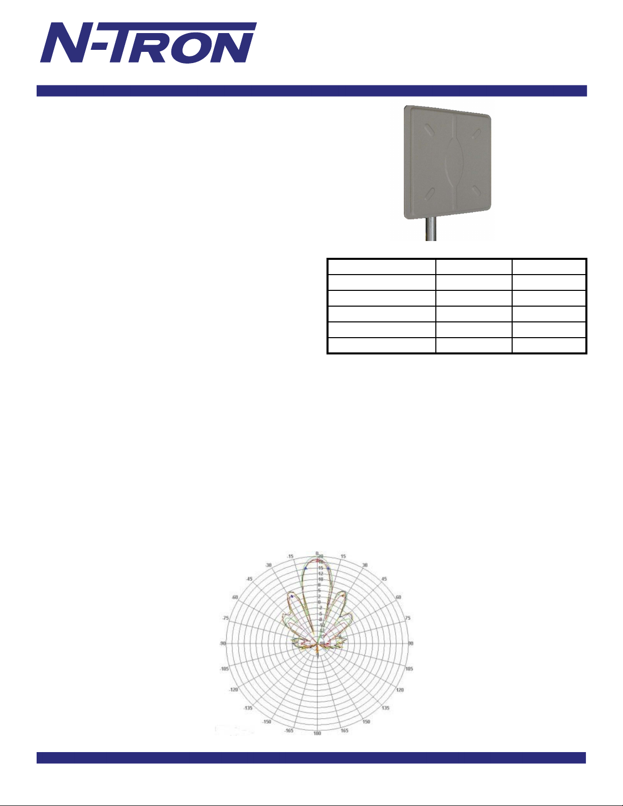
ANT-PAD58-19
, a 5.8 GHz fl at panel directional antenna,
ANT-PAD58-19
offers high gain in a thin low profi le package. The antenna is
constructed of gray UV resistant ABS plastic radome with an
aluminum backplate. The antenna can be used in horizontal
or vertical polarization. The die cast aluminum or galvanized
steel bracket affords +/- 45 deg. up or down tilt adjustment
and the stainless steel hardware assures a long service life. The
ANT -P AD58-19 antenna can be surface mounted or pole mounted
and comes with an integral N female connector standard.
702-W / 702M12-W APPLICATIONS
• Wireless 5GHz LAN applications
• Client Antennas
• 802.11abg applications
SPECIFICATIONS
Frequency Range: 5150 - 5825 MHz
Gain: 19 dBi
Beam width (H&V): 16 deg.
Front to Back: 30 dB
Cross Polarization: 25 dB
VSWR 5150-5350MHz: 2.0:1
VSWR 5470-5825MHz: 1.5:1
Impedance: 50 ohms
Input Power: 100 Watts
o
Operating T emperature: -40
Pole Size (diameter): 1 to 2.5 inches
Weight: 1.10 lbs. (0.5kg)
Dimensions (Diameter x Depth): 7.5" x 7.5" x 0.8"
190mm x 190mm x 21mm
Bracket Tilt: 45 deg.
to 70o C
Antenna Pattern
Range Estimates
Throughput 26Mbps 100Mbps
Distance (Miles) 7.7 1.2
Distance (kilometers) 12.41 1.96
TX Power 20dBm 15dBm
Receive Sensitivity -87dBm -76dBm
Number of Spatial Streams 1 2
*Given the following parameters:
• Free Space loss / 2-ray ground refl ection models
• Antenna is used with an
Ethernet Radio mounted at base level.
• Antenna height: 25ft (7.6 meters) above ground
• Clear line of sight between antennas with no obstructions
of the fi rst Fresnel Zone
• 25 feet of
cable for antenna to Radio connection
• 20MHz wide signal
• Center frequency = 5.80GHz
• 10dB loss assumed for weather conditions
Range estimates are theoretical. Actual results may vary based on installation
conditions. A site survey should be performed as part of the planning process
to determine the presence of RF interference and identify optimum installation
locations for access points and antennas.
N-TRON ANT-CAB-400
N- TRON 702-W
series antenna
or
702M12-W
® 2009
N-TRON
, Corp.
N-TRON
and the
N-TRON
N-TRON
application of
Corporation shall not be liable for any damage resulting from the installation, use, or misuse of this product.
products rests with the end user.
logo are trademarks of
N-TRON
makes no warranties as to the fi tness or suitability of any
N-TRON
, Corp. Specifi cations subject to change without notice. The responsibility for the use and
N-TRON
product for any specifi c application.
REV 090821
N-TRON
 Loading...