

Page 1
THE INDUSTRIAL NETWORK COMPANY
The
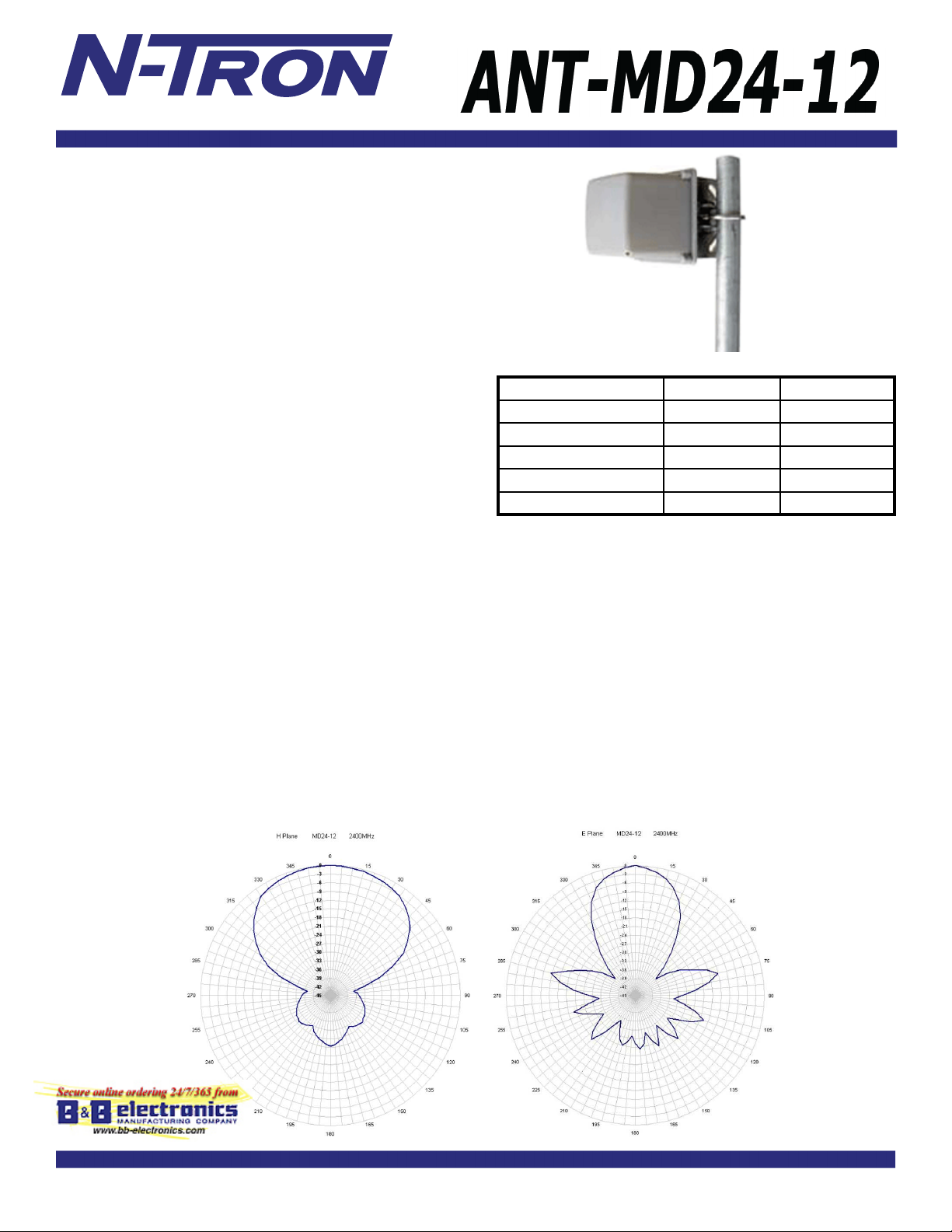
ANT-MD24-12
2.4GHz Mini Directional
antenna is a sub-compact antenna for the most demanding
client applications. The antenna offers high gain in an
ultra-small aesthetically pleasing package. The antenna is
constructed of gray color UV ABS plastic with aluminum
backplate and stainless steel mounting bracket. The antenna
can be used in Horizontal or Vertical Polarization by making
a change to the mounting bracket.The stainless steel bracket
affords +/- 15 deg tilt adjustment. The compact low visual
impact attractive styling blends well in almost any application.
The antenna comes with an integral N Female connector standard.
702-W / 702M12-W APPLICATIONS
• Wireless LAN applications
• Client antennas
• 802.11b/g applications
SPECIFICATIONS
Frequency Range: 2400 - 2483 MHz
Gain: 12 dBi
Horizontal Beamwidth: 65 deg
Vertical Beamwidth: 34 deg
Front to Back: 25 dB
VSWR: 1.5:1
Impedance: 50 ohms
Input Power: 100 Watts
Operating T emparature: -40
Pole Size (diameter): 1 to 1.66 inches
Weight: 0.85 lbs (0.383kg)
Dimensions: 4" x 4" x 4"
102 x 102 x 102 (mm)
Bracket Tilt: 15 deg
o
to 70o C
Range Estimates*
Throughput 26Mbps 100Mbps
Distance (Miles) 4.37 .82
Distance (kilometers) 7.04 1.32
Tx Power 20dBm 15dBm
Receive Sensitivity -88dBm -77dBm
Number of Spacial Streams 1 2
*Given the following parameters:
• Free Space loss / 2-ray ground refl ection models
• Antenna is used with an
Ethernet Radio mounted at base level.
• Antenna height: 25ft (7.6 meters) above ground
• Clear line of sight between antennas with no obstructions
of the fi rst Fresnel Zone
• 25 feet of
N-TRON ANT-CAB-400
cable for antenna to Radio connection
• 20MHz wide signal
• Center frequency = 2.45GHz
• 10dB loss assumed for weather conditions
Range estimates are theoretical. Actual results may vary based on installation
conditions. A site survey should be performed as part of the planning process
to determine the presence of RF interference and identify optimum installation
locations for access points and antennas.
N- TRON 702-W
series antenna
or
702M12-W
Antenna Patterns
® 2009
N-TRON
, Corp.
N-TRON
and the
N-TRON
N-TRON
application of
Corporation shall not be liable for any damage resulting from the installation, use, or misuse of this product.
products rests with the end user.
logo are trademarks of
N-TRON
makes no warranties as to the fi tness or suitability of any
N-TRON
, Corp. Specifi cations subject to change without notice. The responsibility for the use and
N-TRON
product for any specifi c application.
REV 090810
N-TRON
 Loading...