

Page 1

ADAM-6000 Series
Ethernet-based
Data Acquisition and
Control Modules
User Manual
Page 2

Copyright
The documentation and the software included with this product are copyrighted 2009 by Advantech Co., Ltd. All rights are reserved. Advantech
Co., Ltd. reserves the right to make improvements in the products
described in this manual at any time without notice. No part of this manual may be reproduced, copied, translated or transmitted in any form or
by any means without the prior written permission of Advantech Co., Ltd.
Information provided in this manual is intended to be accurate and reliable. However, Advantech Co., Ltd. assumes no responsibility for its use,
nor for any infringements of the rights of third parties, which may result
from its use.
Acknowledgements
Intel and Pentium are trademarks of Intel Corporation.
Microsoft Windows and MS-DOS are registered trademarks of
Microsoft Corp.
All other product names or trademarks are properties of their respective
owners.
Printed in Taiwan June 2011 4th Edition
ADAM-6000 Series User Manual ii
Page 3

Product Warranty (2 years)
Advantech warrants to you, the original purchaser, that each of its products will be free from defects in materials and workmanship for two years
from the date of purchase.
This warranty does not apply to any products which have been repaired or
altered by persons other than repair personnel authorized by Advantech,
or which have been subject to misuse, abuse, accident or improper installation. Advantech assumes no liability under the terms of this warranty as
a consequence of such events.
Because of Advantech’s high quality-control standards and rigorous testing, most of our customers never need to use our repair service. If an
Advantech product is defective, it will be repaired or replaced at no
charge during the warranty period. For out-of-warranty repairs, you will
be billed according to the cost of replacement materials, service time and
freight. Please consult your dealer for more details.
If you think you have a defective product, follow these steps:
1. Collect all the information about the problem encountered. (For
example, CPU speed, Advantech products used, other hardware
and software used, etc.) Note anything abnormal and list any
onscreen messages you get when the problem occurs.
2. Call your dealer and describe the problem. Please have your manual, product, and any helpful information readily available.
3. If your product is diagnosed as defective, obtain an RMA (return
merchandize authorization) number from your dealer. This allows
us to process your return more quickly.
4. Carefully pack the defective product, a fully-completed Repair and
Replacement Order Card and a photocopy proof of purchase date
(such as your sales receipt) in a shippable container. A product
returned without proof of the purchase date is not eligible for warranty service.
5. Write the RMA number visibly on the outside of the package and
ship it prepaid to your dealer.
iii
Page 4

Technical Support and Assistance
Step 1. Visit the Advantech web site at www.advantech.com/support
where you can find the latest information about the product.
Step 2. Contact your distributor, sales representative, or Advantech's cus-
tomer service center for technical support if you need additional
assistance. Please have the following information ready before
you call:
- Product name and serial number
- Description of your peripheral attachments
- Description of your software (OS, version, software, etc.)
- A complete description of the problem
- The exact wording of any error messages
ADAM-6000 Series User Manual iv
Page 5

Chapter 1 Understanding Your System ......................... 2
1.1 Introduction ....................................................................... 2
1.2 Major Features................................................................... 3
1.3 Specifications .................................................................... 5
1.4 Dimensions........................................................................ 6
1.5 LED Status ........................................................................ 6
Figure 1.1:ADAM-6000 System Architecture ............... 2
1.2.1 Ethernet-enabled DA&C I/O Modules .......................... 3
1.2.2 Intelligent I/O Modules .................................................. 3
1.2.3 Mixed I/O to Fit All Applications .................................. 3
1.2.4 Remote Monitoring & Diagnosis ................................... 4
1.2.5 Industrial Standard Modbus/TCP Protocol .................... 4
1.2.6 Customized Web Page ................................................... 4
1.2.7 Modbus/TCP Software Support ..................................... 4
Figure 1.2:ADAM-6000 Module Dimension ................ 6
Figure 1.3:LED Indicators ............................................. 6
Chapter 2 Selecting Your Hardware ............................... 8
2.1 Selecting an I/O Module ................................................... 8
2.2 Selecting a Link Terminal & Cable................................... 9
2.3 Selecting an Operator Interface....................................... 11
Table 2.1:I/O Selection Guidelines ................................ 9
Figure 2.1:Ethernet Terminal and Cable Connection .. 10
Table 2.2:Ethernet RJ-45 port Pin Assignment ........... 10
Chapter 3 Hardware Installation Guide ....................... 14
3.1 Determining the Proper Environment ............................. 14
3.1.1 Package Contents ......................................................... 14
3.1.2 System Requirements .................................................. 14
3.2 Mounting ......................................................................... 15
3.2.1 Panel Mounting ............................................................ 15
Figure 3.1:Panel Mounting Dimensions ...................... 15
Figure 3.2:Fix Module on theBracket .......................... 16
3.2.2 DIN-rail mounting ....................................................... 16
Figure 3.3: Fix Module on the DIN-rail Adapter ......... 17
Figure 3.4:Secure Module to a DIN-rail ...................... 18
3.3 Wiring & Connections .................................................... 18
3.3.1 Power Supply Wiring ................................................... 18
Figure 3.5:ADAM-6000 Module Power Wiring ......... 19
3.3.2 I/O Module Wiring ...................................................... 19
Chapter 4 I/O Module Introduction .............................. 22
4.1 Analog Input Modules..................................................... 22
4.1.1 ADAM-6015 ................................................................ 22
Figure 4.1:ADAM-6015 RTD Input Wiring ................ 24
4.1.2 ADAM-6017 ................................................................ 24
Figure 4.2:ADAM-6017 Analog Input Wiring ............ 26
Figure 4.3:ADAM-6017 Analog Input Type Setting ... 27
v
Page 6

Figure 4.4:ADAM-6017 Digital Output Wiring .......... 27
4.1.3 ADAM-6018 ................................................................ 28
Figure 4.5:ADAM-6018 8-ch Thermocouple Input .... 28
Figure 4.6:ADAM-6018 Thermocouple Input Wiring 30
Figure 4.7:ADAM-6018 Digital Output Wiring .......... 31
4.1.4 ADAM-6024 ................................................................ 31
Figure 4.8:ADAM-6024 Jumper Settings .................... 34
Figure 4.9:ADAM-6024 AI/O Wiring ......................... 34
Figure 4.10:ADAM-6024 DI Wiring ........................... 35
Figure 4.11:ADAM-6024 DO Wiring ......................... 35
4.2 Digital I/O Modules ........................................................ 36
4.2.1 ADAM-6050 ................................................................ 36
Figure 4.12:ADAM-6050 Digital Input Wiring .......... 37
Figure 4.13:ADAM-6050 Digital Output Wiring ........ 38
4.2.2 ADAM-6051 ................................................................ 38
Figure 4.14:ADAM-6051 Digital Input Wiring .......... 40
Figure 4.15:ADAM-6051 Counter (Frequency) Input 41
Figure 4.16:ADAM-6051 DO Wiring ......................... 41
4.2.3 ADAM-6052 ................................................................ 42
Figure 4.17:ADAM-6052 DI (Dry Contact) Wiring ...43
Figure 4.18:ADAM-6052 DI (Wet Contact) Wiring ... 44
Figure 4.19:ADAM-6052 Digital Output Wiring ........ 44
4.2.4 ADAM-6060 ................................................................ 45
Figure 4.20:ADAM-6060 Digital Input Wiring .......... 47
Figure 4.21:ADAM-6060 Relay Output Wiring .......... 47
4.2.5 ADAM-6066 ................................................................ 48
Figure 4.22:ADAM-6066 Digital Input Wiring .......... 50
Figure 4.23:ADAM-6066 Relay Output Wiring .......... 50
4.2.6 ADAM-6050W ............................................................ 51
Figure 4.24:ADAM-6050W Digital Input Wiring ....... 52
Figure 4.25:ADAM-6050W Digital Output Wiring .... 53
4.2.7 ADAM-6051W ............................................................ 53
Figure 4.26:ADAM-6051W Digital Input Wiring ....... 55
Figure 4.27:ADAM-6051W Counter (Frequency) ...... 56
Figure 4.28:ADAM-6051W Digital Output Wiring .... 56
4.2.8 ADAM-6060W ............................................................ 57
Figure 4.29:ADAM-6060W Digital Input Wiring ....... 59
Figure 4.30:ADAM-6060W Relay Output Wiring ...... 59
Chapter 5 System Configuration Guide........................ 62
5.1 System Hardware Configuration ..................................... 62
5.1.1 System Requirements ................................................. 62
5.1.2 Communication Interface ............................................ 62
5.2 Install ADAM.NET Utility Software .............................. 62
5.3 ADAM.NET Utility Overview........................................ 63
5.3.1 ADAM.NET Utility Operation Window ..................... 63
ADAM-6000 Series User Manual vi
Page 7

Figure 5.1:ADAM.NET Utility Operation Window .... 63
Figure 5.2:ADAM.NET Utility Toolbar ...................... 66
5.3.2 Search ADAM-6000 Modules ..................................... 67
Figure 5.3:Access Control Setting ............................... 71
5.3.3 I/O Module Configuration .......................................... 72
Figure 5.4:Channel & GCL Configuration .................. 72
Figure 5.5:Channels Range Configuration Area .......... 73
Figure 5.6:Integration Time Configuration Area ......... 74
Figure 5.7:Analog Input Trend Log ............................. 75
Figure 5.8:Analog Input Average Setting .................... 76
Figure 5.9:Analog Input Alarm Mode Configuration .. 77
Figure 5.10:ADAM-6024 Input Tab ............................ 79
Figure 5.11:ADAM-6024 Output Tab ......................... 80
Figure 5.12:ADAM-6050 Channel Setting .................. 82
Figure 5.13:Fail Safe Value Configuration .................. 83
Figure 5.14:Individual Channel Configuration: DI ..... 84
Figure 5.15:Individual Channel Configuration: DO .... 86
Figure 5.16:Low to High Delay Output Mode ............ 88
Figure 5.17:Low to High Delay Output Mode ............ 88
5.3.4 Peer-to-Peer Function ................................................. 89
Figure 5.18:Basic mode for Peer-to-Peer .................... 90
Figure 5.19:Advanced mode for Peer-to-Peer ............. 90
Figure 5.20:Peer-to-Peer Configuration Tab ............... 92
Figure 5.21:Peer-to-Peer Basic Mode Configuration .. 93
Figure 5.22:Building the Mapping Relationship .........95
Figure 5.23:P-to-P Advanced Mode Configuration ..... 96
Figure 5.24:Copy One Setting to Other Channels ....... 98
5.4 ADAM-6000 Web Server ............................................. 99
5.5 Java Applet Customization.............................................. 99
5.5.1 Introduction .................................................................. 99
Figure 5.25:Structure of the ADAM6060.jar file ...... 103
Figure 5.26:Firmware Upgrade .................................. 104
5.6 Source Code of Java Applet Example........................... 105
Chapter 6 Planning Your Application Program ........ 114
6.1 Introduction ................................................................... 114
6.2 ADAM .NET Class Library ......................................... 114
6.3 ADAM-6000 Commands .............................................. 117
6.4 ASCII Commands for ADAM-6000 Modules ............. 124
Figure 6.1:Modifying ADAM-6050 .NET ................ 115
Figure 6.2:Launching ADAM .NET Class Library ... 116
6.3.1 Command Structure ................................................... 117
6.3.2 Modbus Function Code Introductions ....................... 118
6.4.1 Syntax of ASCII ......................................................... 124
6.4.2 System Command Set ............................................... 125
6.4.3 Analog Input Command Set ...................................... 130
6.4.4 Analog Input Alarm Command Set Set ..................... 144
vii
Page 8

6.4.5 Universal I/O Command Set ...................................... 154
6.4.6 Digital Input/Output Command Set ........................... 164
Chapter 7 Graphic Condition Logic(GCL)................. 170
7.1 Overview ....................................................................... 170
7.2 GCL Configuration Environment.................................. 171
7.3 Configure Four Stages of One Logic Rule.................... 176
7.4 Internal Flag for Logic Cascade and Feedback ............. 194
7.5 Download Logic and Online Monitoring ...................... 200
7.6 Typical Applications with GCL .................................... 203
ADAM-6000 Series User Manual viii
Figure 7.1:GCL Configuration Environment ............. 171
Figure 7.2:Four Stages for One Logic Rule ............... 173
7.3.1 Input Condition Stage ................................................ 176
Figure 7.3:Input Condition Stage Configuration ....... 176
Figure 7.4:Engineer Unit and Current Value ............. 178
Figure 7.5:Scaling Function of Analog Input Mode .. 179
7.3.2 Logic Stage ................................................................ 182
Figure 7.6:Logic Stage Configuration ....................... 182
7.3.3 Execution Stage ......................................................... 184
Figure 7.7:Execution Stage Configuration ................ 184
Figure 7.8:Send to Next Rule Function ..................... 185
Figure 7.9:The Next Logic Rule ................................ 186
7.3.4 Output Stage .............................................................. 186
Figure 7.10:Output Stage Configuration ................... 187
Figure 7.11:Remote Message Output ........................ 192
7.4.1 Logic Cascade ............................................................ 194
Figure 7.12:Architecture of Local Logic Cascade ..... 195
Figure 7.13:Configuration of Logic Rule 1 ............... 196
Figure 7.14:Configuration of Logic Rule 2 ............... 196
Figure 7.15:Configuration of Logic Rule 3 ............... 197
Figure 7.16: Distributed Logic Cascade .................... 198
Figure 7.17:Configuration of Logic Rule 1 ............... 198
Figure 7.18:Configuration of Logic Rule 2 ............... 199
Figure 7.19:Configuration of Logic Rule 3 ............... 199
7.4.2 Feedback .................................................................... 200
Figure 7.20:Building Logic Feedback ....................... 200
Figure 7.21:Online Monitoring Function ................... 201
Figure 7.22:GCL Execution Sequence ...................... 202
Figure 7.23:Ladder Diagram for On/Off Control ...... 204
Figure 7.24:GCL Logic for On/Off Control .............. 204
Figure 7.25:Time Chart for Sequence Control .......... 205
Figure 7.26:GCL Logic for Sequence Control .......... 206
Figure 7.27:Time Chart for 12 DI to 1 DO ................ 207
Figure 7.28:GCL Logic for 12 DI to 1 DO ............... 208
Figure 7.29:Time Chart for Flicker Application ........ 208
Figure 7.30:GCL Logic for Flicker ........................... 209
Figure 7.31:Time Chart for Rising Edge ................... 209
Page 9

Figure 7.32:Ladder Diagram for Rising Edge ........... 210
Figure 7.33:GCL Logic for Rising Edge ................... 211
Figure 7.34:Time Chart for Falling Edge .................. 211
Figure 7.35:Ladder Diagram for Falling Edge .......... 212
Figure 7.36:GCL Logic for Falling Edge .................. 213
Figure 7.37:Time Chart for Sequence Control .......... 213
Figure 7.38:GCL Logic for Sequence Control .......... 214
Figure 7.39:GCL Logic for Event Trigger ................. 215
Figure 7.40:Event Trigger Configuration ..................215
Appendix A Design Worksheets ...................................... 218
Table A.1:I/O Data Base ............................................ 218
Table A.2:Summary Required Modules .................... 219
Table A.3:Table for Programming ............................. 220
Appendix B Data Formats and I/O Range ..................... 222
B.1 ADAM-6000 Commands Data Formats ....................... 222
B.1.1 Command Structure ................................................... 222
Figure B.1:Request Comment Structure .................... 223
Figure B.2:Response Comment Structure ................. 223
B.1.2 Modbus Function Code Introductions ....................... 224
Table B.1:Response Comment Structure ................... 224
B.2 ADAM-6000 I/O Modbus Mapping Table ................... 230
B.2.1 ADAM-6015 .............................................................. 230
B.2.2 ADAM-6017 .............................................................. 232
B.2.3 ADAM-6018 .............................................................. 234
B.2.4 ADAM-6024 .............................................................. 236
B.2.5 ADAM-6050/6050W ................................................. 237
B.2.6 ADAM-6051/6051W ................................................. 239
B.2.7 ADAM-6052 16-ch Digital I/O Module ..................... 243
B.2.8 ADAM-6060/6060W/6066 ........................................ 245
Appendix C Grounding Reference.................................. 250
C.1 Field Grounding and Shielding Application ................. 250
C.2 Grounding...................................................................... 251
C.2.1 The ‘Earth’ for Reference .......................................... 251
Figure C.1:Think of the Earth as a Ground. .............. 251
C.2.2 The ‘Frame Ground’ and ‘Grounding Bar’ ................ 252
Figure C.2:Grounding Bar ......................................... 252
Figure C.3:Normal and Common Mode. ................... 252
C.2.3 Normal Mode and Common Mode ............................ 253
Figure C.4:Normal and Common Mode. .................. 253
C.2.4 Wire impedance ......................................................... 254
Figure C.5:High Voltage Transmission ..................... 254
Figure C.6:Wire Impedance ....................................... 255
C.2.5 Single Point Grounding ............................................. 255
Figure C.7:Single Point Grounding (1) ...................... 255
Figure C.8:Single point grounding (2) ....................... 256
ix
Page 10

C.3 Shielding........................................................................ 256
C.3.1 Cable Shield ............................................................... 256
Figure C.9:Single isolated cable ................................ 256
Figure C.10:Double isolated cable ............................. 257
C.3.2 System Shielding ....................................................... 258
Figure C.11:System Shielding ................................... 258
Figure C.12:The characteristic of the cable ............... 259
Figure C.13:System Shielding (1) ............................. 259
Figure C.14:System Shielding (2) ............................. 260
C.4 Noise Reduction Techniques......................................... 260
Figure C.15:Noise Reduction Techniques ................. 261
C.5 Check Point List ............................................................ 261
ADAM-6000 Series User Manual x
Page 11

2
1
CHAPTER
Understanding
Your System
Sections include:
• Introduction
• Major Features
• Specifications
• Dimensions
• LED Status
Page 12
Chapter 1 Understanding Your System
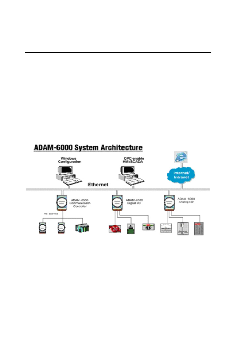
1.1 Introduction
ADAM-6000 Ethernet-based data acquisition and control modules provide I/O, data acquisitions, and networking in one module to build a costeffective, distributed monitoring and control solution for a wide variety of
applications. Through standard Ethernet networking, ADAM-6000
retrieves I/O values from sensors, and can publish them as a real-time I/O
values to networking nodes via LAN, Intranet, or Internet. With Ethernetenabled technology, ADAM-6000 series modules build up a cost-effective DA&C system for Building Automation, Environmental Monitoring,
Facility Management and eManufacturing applications. Please refer to
Figure 1-1 for a brief overview of the ADAM-6000 system architecture.
Figure 1.1: ADAM-6000 System Architecture
ADAM-6000 Series User Manual 2
Page 13

1.2 Major Features
1.2.1 Ethernet-enabled DA&C I/O Modules
ADAM-6000 is based on popular Ethernet networking standards used in
most business environments. Users can easily add ADAM-6000 I/O modules to existing Ethernet networks, or use ADAM-6000 modules in new
Ethernet-enabled eManufacturing networks. ADAM-6000 modules feature a 10/100 Mbps Ethernet chip and support industrial popular Modbus/
TCP protocols over TCP/IP for data connection. ADAM-6000 also supports UDP protocol over Ethernet networking. With UDP/IP, ADAM6000 I/O modules can actively send I/O data stream to 8 Ethernet nodes.
Through Ethernet networking, HMI/SCADA systems, and controllers,
users can access or gather real-time data from ADAM-6000 Ethernet
enabled DA&C modules. This data can then be integrated with business
systems to compile valuable business information.
1.2.2 Intelligent I/O Modules
Upgraded from traditional I/O modules, the ADAM-6000 series have prebuilt intelligent mathematic functions to empower system capacity. The
Digital Input modules provide Counter, Totalizer functions; the Digital
Output modules provide pulse output, delay output functions; the Analog
Input modules provide the Max./Min./Average data calculation; the Analog Output modules provide the PID loop control function.
1.2.3 Mixed I/O to Fit All Applications
ADAM-6000 series mixed I/O design provides the most cost-effective
I/O usage for application systems. The most common used I/O type for
single function units are collected in one module. This design concept not
only saves I/O usage and saves costs, but also speeds up I/O relative operations. For small DA&C system or standalone control units from mid to
large scales, ADAM-6000’s mixed I/O design can easily fit application
needs with one or two modules only. With additional embedded control
modules, ADAM-6000 can easily create a localized, less complex, and
more distributed I/O architecture.
3 Chapter 1
Page 14

1.2.4 Remote Monitoring & Diagnosis
Each ADAM-6000 module features a pre-built I/O module web page to
display real-time I/O data values, alarms, and module status thru LAN or
Internet. Through any Internet browser, users can monitor real-time I/O
data values and alarms at local or remote sites. Then, the web-enabled
monitoring system is completed immediately without any programming.
1.2.5 Industrial Standard Modbus/TCP Protocol
ADAM-6000 modules support the popular industrial standard, Modbus/
TCP protocol, to connect with Ethernet Controller or HMI/SCADA software built with Modbus/TCP driver. Advantech also provides OPC server
for Modbus/TCP to integrate ADAM-6000 I/O real-time data value with
OPC client enabled software, freeing users from driver development.
1.2.6 Customized Web Page
Since ADAM-6000 modules build in a default web page, users can monitor and control the I/O status in anywhere through Internet Explorer
Browser. Moreover, ADAM-6000 modules can download user-defined
web pages for individual applications. Advantech has provided sample
programs of JAVA Script for users reference to design their own operator
interface, then download it into the specific ADAM-6000 modules via
Windows Utility.
1.2.7 Modbus/TCP Software Support
The ADAM-6000 firmware is a built-in Modbus/TCP server. Therefore,
Advantech provides the necessary OPC Server, ADAM .NET Class
Library and Windows ADAM .NET Utility for users. Users can configure
this DA&C system via Windows Utility; integrate with HMI software
package via Modbus/TCP driver or Modbus/TCP OPC Server. Even
more, you can use the DLL driver and ActiveX to develop your own
applications.
ADAM-6000 Series User Manual 4
Page 15

1.3 Specifications
Ethernet: Wired: 10/100 Base-T
Wireless: 802.11b WLAN
Wiring: UTP, category 5 or greater
Bus Connection: RJ45 modular jack
Comm. Protocol: Modbus/TCP on TCP/IP and UDP
Data Transfer Rate: Up to 100 Mbps
Unregulated 10 to 30 VDC
Status Indicator: Power, CPU, Communication
(Link, Collide, 10/100 Mbps, Tx, Rx)
Case: ABS + PC with captive mounting hardware
Screw Terminal Block: Accepts 0.5 mm 2 to 2.5 mm 2 , 1 - #12 or
2 - #14 to #22 AWG
NOTE: Equipment will operate below 30% humidity,
however, static electricity problems occur much
more frequently at lower humidity levels. Make
sure you take adequate precautions when you
touch the equipment. Consider using ground
straps, anti-static floor coverings, etc. if you use
the equipment in low humidity environments.
5 Chapter 1
Page 16
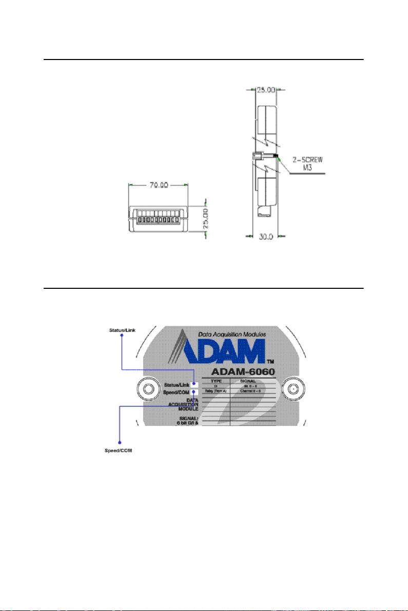
1.4 Dimensions
The following diagram show the dimensions of the l/O modules. (mm)
Figure 1.2: ADAM-6000 Module Dimension
1.5 LED Status
There are two LEDs on the ADAM-6000 I/O Series front panel. Each
LED has two indicators to represent system status, as explained below:
Figure 1.3: LED Indicators
(1) Status: Red indicator. Blinks when ADAM-6000 module is running.
(2) Link: Green indicator. On whenever the Ethernet is connected.
(3) Speed: Red indicator. On when Ethernet speed is below 100 Mbps.
(4) COM: Green indicator. Blinks whenever the the ADAM-6000
module is transmitting or receiving data via Ethernet.
ADAM-6000 Series User Manual 6
Page 17

2
2
CHAPTER
Selecting
Your Hardware
Sections include:
• Selecting an I/O Module
• Selecting a Link Terminal & Cable
• Selecting an Operator Interface
Page 18

Chapter 2 Selecting Your Hardware
2.1 Selecting an I/O Module
To organize an ADAM-6000 remote data acquisition & control system,
you need to select I/O modules to interface the host PC with field devices
or processes that you have previously determined. There are several
things should be considered when you select the I/O modules.
• What type of I/O signal is applied in your system?
• How much I/O is required to your system?
• How will you place the modules to handle I/O points in individual areas
of an entire field site?
• How many modules are required for distributed I/O point arrangement?
• How many hubs are required for the connection of these devices?
• What is the required voltage range for each I/O module?
• What isolation environment is required for each I/O module?
• What are the noise and distance limitations for each I/O module?
Refer to table 2-1 for I/O module selection guidelines
ADAM-6000 Series User Manual 8
Page 19

.
Table 2.1: I/O Selection Guidelines
Choose this
type of I/O
module:
Discrete input
module and
block I/O
module
Discrete
output module
and block I/O
module
Analog
input
module
Analog
output
module
For these types of field devices
or operations (examples):
Selector switches, pushbuttons,
photoelectric eyes, limit
switches, circuit breakers, proximity switches, level switches,
motor starter contacts, relay
contacts, thumbwheel switches
Alarms, control relays, fans,
lights, horns, valves, motor
starters, solenoids
Thermocouple signals, RTD
signals, temperature transducers, pressure transducers, load
cell transducers, humidity transducers, flow transducers,
potentiometers.
Analog valves, actuators, chart
recorders, electric motor drives,
analog meters
Explanation:
Input modules sense
ON/OFF or OPENED/
CLOSED signals.
Output module signals
interface with ON/OFF
or OPENED/CLOSED
devices
Convert continuous
analog signals into
input values for host
device
Interpret host device’s
output to analog signals (generally
through transducers)
for field devices.
2.2 Selecting a Link Terminal & Cable
Use the RJ-45 connector to connect the Ethernet port of the ADAM-6000
to the Hub. The cable for connection should be Category 3 (for 10Mbps
data rate) or Category 5 (for 100Mbps data rate) UTP/STP cable, which is
compliant with EIA/TIA 586 specifications. Maximum length between
the Hub and any ADAM-6000 modules is up to 100 meters (appr. 300 ft).
9 Chapter 2
Page 20
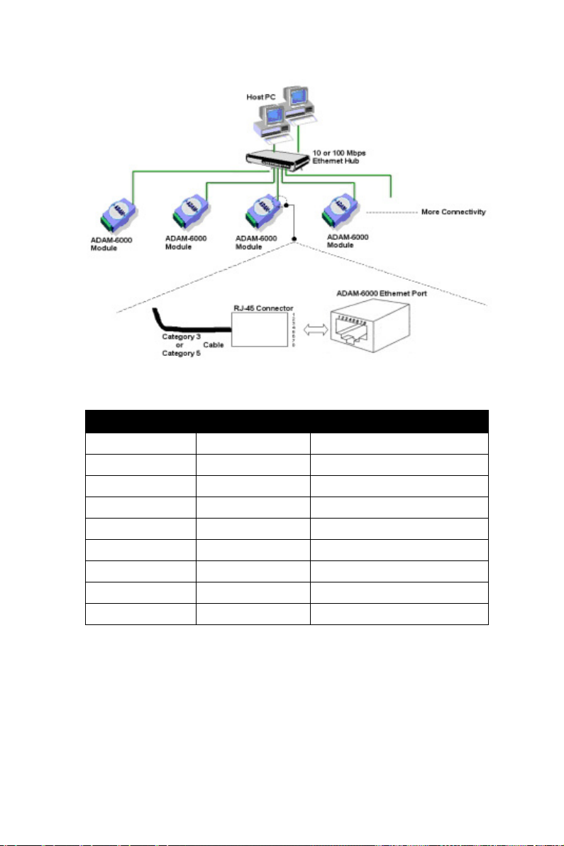
Figure 2.1: Ethernet Terminal and Cable Connection
Table 2.2: Ethernet RJ-45 port Pin Assignment
PIN NUMBER SIGNAL FUNCTION
1 RD+ Receive (+)
2 RD- Receive (-)
3 TD+ Transmit (+)
4 (Not Used) -
5 (Not Used) -
6 TD- Transmit (-)
7 (Not Used) -
8 (Not Used) -
ADAM-6000 Series User Manual 10
Page 21

2.3 Selecting an Operator Interface
To complete your Data Acquisition and Control system, selecting the
operator interface is necessary. Adopting the Modbus/TCP Protocol,
ADAM-6000 I/O modules exhibit high ability in system integration for
various applications.
If you want to read the real-time status of ADAM-6000 modules through
the web page from anywhere without any engineering effort, there are
many Internet browser software:
• Internet Explorer, Netscape, and other browser with JAVA Machine
If you want to develop your own web pages in the ADAM-6000 modules,
the JAVA Script will be the quick and easy programming tool to design a
specific operator interface.
• J2EE Development Kit
If you want to integrate ADAM-6000 I/O with HMI (Human Machine
Interface) software in a SCADA (Supervisory Control and Data Acquisition) system, there are a lot of HMI software packages, which support
Modbus/TCP driver.
• Advantech Studio
• Wonderware InTouch
• Intellution Fix of i-Fix
• Any other software support Modbus/TCP protocol
Moreover, Advantech also provides OPC Server, the most easy-to-use
data exchange tool in worldwide. Any HMI software designed with OPC
Client would be able to access ADAM-6000 I/O modules.
• Modbus/TCP OPC Server
If you want to develop your own applications, the ADAM.NET Class
Library will be the best tools to build up users operator interface.
With these ready-to-go application software packages, tasks such as
remote data acquisition, process control, historical trending and data
analysis require only a few keystrokes.
11 Chapter 2
Page 22

ADAM-6000 Series User Manual 12
Page 23

2
3
CHAPTER
Hardware
Installation Guide
Sections include:
• Determining the Proper Environment
• Mounting
• Wiring & Connections
Page 24

Chapter 3 Hardware Installation Guide
3.1 Determining the Proper Environment
Prior to installing ADAM-6000 modules, please check the following.
3.1.1 Package Contents
Unpack the shipped boxes and make sure that the contents include:
• ADAM-6000 module with one bracket and DIN-rail adapter
• ADAM-6000 module User Manual
3.1.2 System Requirements
Host Computer
• IBM PC compatible computer with 486 CPU (Pentium recommended)
• Microsoft 95/98/2000/NT 4.0 (SP3 or SP4)/XP
• At least 32 MB RAM
• 20 MB of hard disk space available
• VGA color monitor
• 2x or higher speed CD-ROM
• Mouse or other pointing devices
• 10 or 100 Mbps Ethernet Card
10 or 100 Mbps Ethernet Hub (at least 2 ports)
Two Ethernet Cables with RJ-45 connector
Power supply for ADAM-6000 (+10 to +30 V Unregulated)
Wireless AP (ADAM-6000W module)
ADAM-6000 Series User Manual 14
Page 25
3.2 Mounting
ADAM-6000 modules are designed as compact units and are allowed to
be installed in the field site under the following methods.
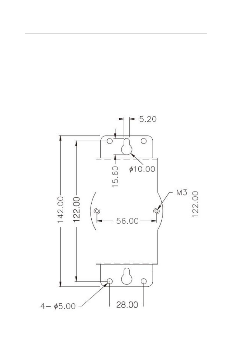
3.2.1 Panel Mounting
Each ADAM-6000 Module is packed with a plastic panel mounting
bracket. Users can refer the dimensions of the bracket to configure an
optimal placement in a panel or cabinet. Fix the bracket first, then, fix the
ADAM-6000 module on the bracket.
Figure 3.1: Panel Mounting Dimensions
15 Chapter 3
Page 26
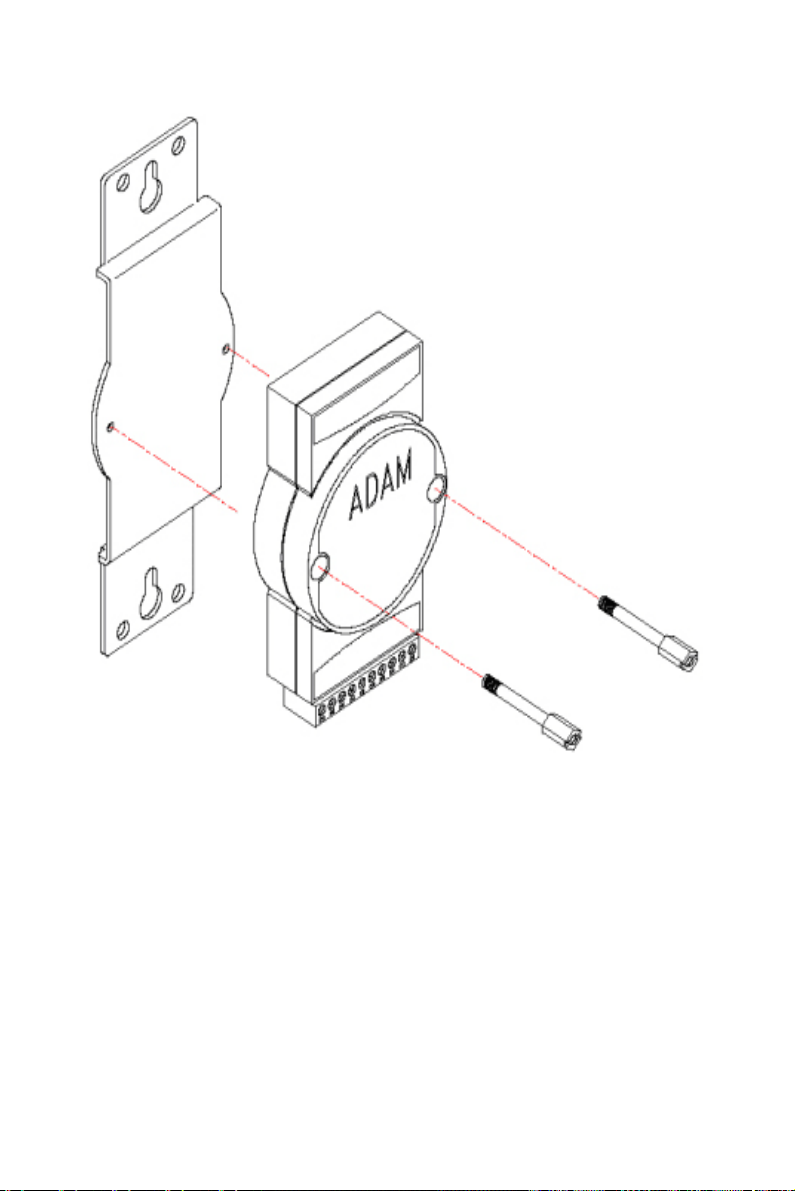
Figure 3.2: Fix Module on theBracket
3.2.2 DIN-rail mounting
The ADAM-6000 module can also be secured to the cabinet by using
mounting rails. Fix the ADAM-6000 module with the DIN-rail adapter as
Figure 3-3. Then secure it on the DIN-rail as Figure 3-4. If you mount the
module on a rail, you should also consider using end brackets at each end
of the rail. The end brackets help keep the modules from sliding horizontally along the rail.
ADAM-6000 Series User Manual 16
Page 27
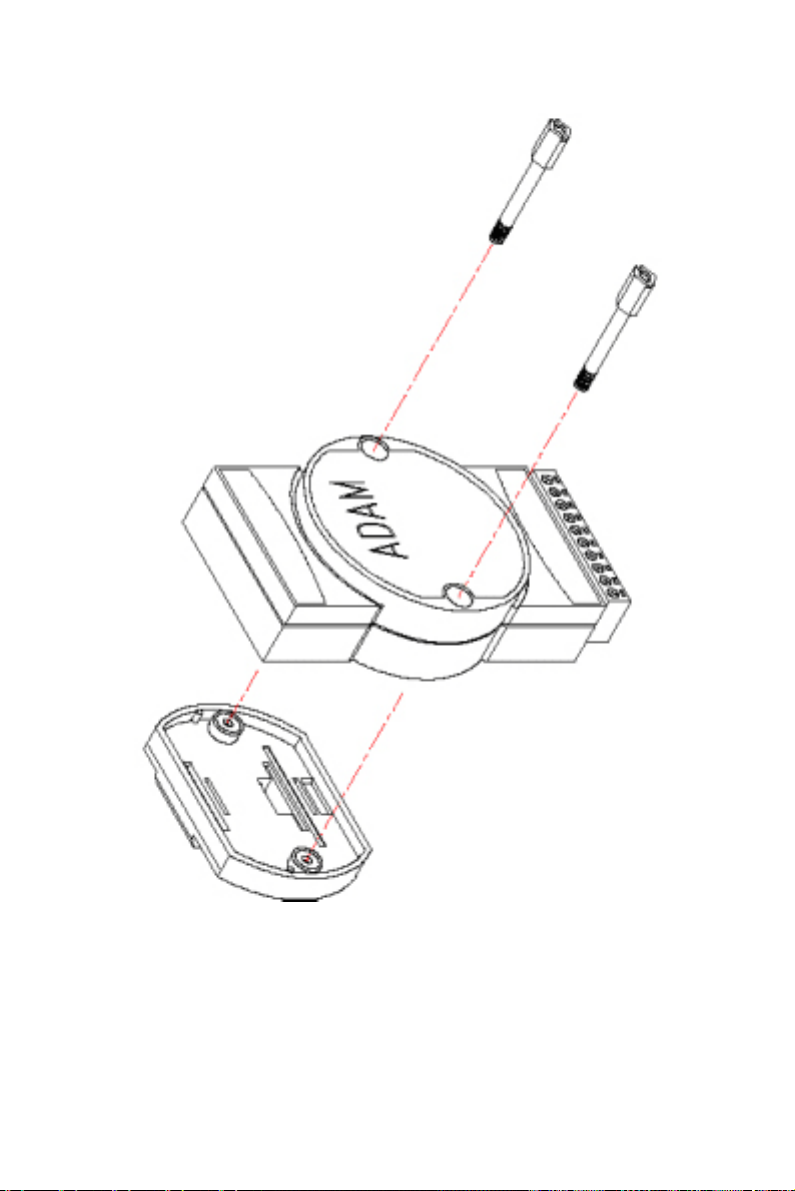
Figure 3.3: Fix Module on the DIN-rail Adapter
17 Chapter 3
Page 28
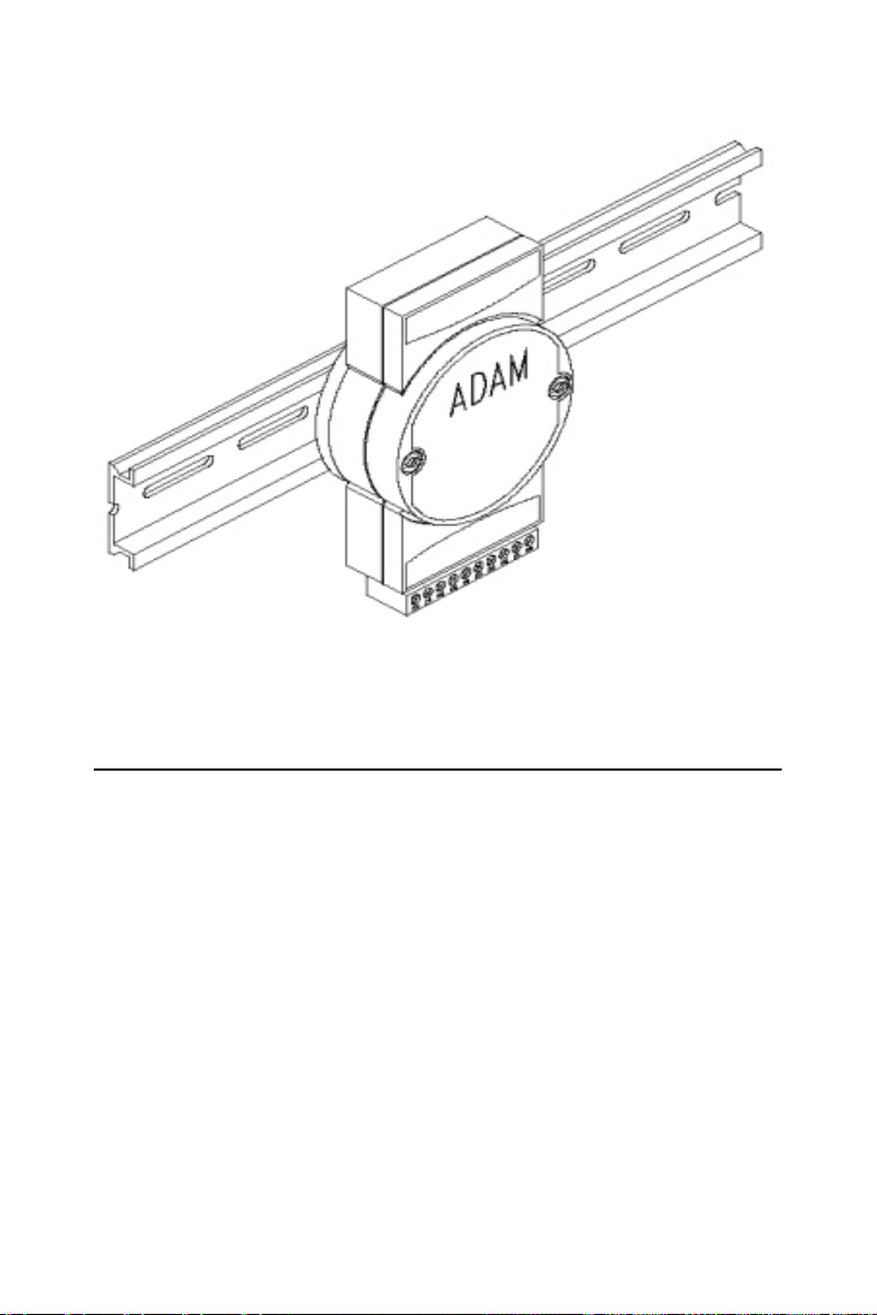
Figure 3.4: Secure Module to a DIN-rail
3.3 Wiring & Connections
This section provides basic information on wiring the power supply, I/O
units, and network connection.
3.3.1 Power Supply Wiring
Although the ADAM-6000/TCP systems are designed for a standard
industrial unregulated 24 VDC power supply, they accept any power unit
that supplies within the range of +10 to +30 VDC. The power supply ripple must be limited to 200 mV peak-to-peak, and the immediate ripple
voltage should be maintained between +10 and +30 VDC. Screw terminals +Vs and GND are for power supply wiring.
Note: The wires used should be at least 2 mm.
ADAM-6000 Series User Manual 18
Page 29
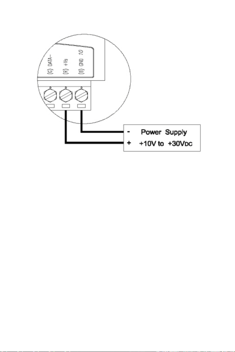
Figure 3.5: ADAM-6000 Module Power Wiring
We advise that the following standard colors (indicated on the modules)
be used for power lines:
+Vs (R) Red
GND (B) Black
3.3.2 I/O Module Wiring
The system uses a plug-in screw terminal block for the interface between
I/O modules and field devices. The following information must be considered when connecting electrical devices to I/O modules.
1. The terminal block accepts wires from 0.5 mm to 2.5 mm.
2. Always use a continuous length of wire. Do not combine wires.
3. Use the shortest possible wire length.
4. Use wire trays for routing where possible.
5. Avoid running wires near high-energy wiring.
6. Avoid running input wiring in close proximity to output wiring.
7. Avoid creating sharp bends in the wires.
19 Chapter 3
Page 30

ADAM-6000 Series User Manual 20
Page 31

2
4
CHAPTER
I/O Module
Introduction
Sections include:
• Analog Input Modules
• Digital I/O Modules
• 16-ch Digital I/O w/ Counter
Page 32

Chapter 4 I/O Module Introduction
4.1 Analog Input Modules
Analog input modules use an A/D converter to convert sensor voltage,
current, thermocouple or RTD signals into digital data. The digital data is
then translated into engineering units. When prompted by the host computer, the data is sent through a standard 10/100 Base-T Ethernet or IEEE
802.11b WLAN. Users can read the current status via pre-built webpage
or HMI software supported Modbus/TCP protocol. The analog input
modules protect your equipment from ground loops and power surges by
providing opto-isolation of the A/D input and transformer based isolation.
4.1.1 ADAM-6015
7-ch Isolated RTD Input Module
The ADAM-6015 is a 16-bit, 7-channel RTD input module that provides
programmable input ranges on all channels. It accepts various RTD inputs
(PT100, PT1000, Balco 500 & Ni) and provides data to the host computer
in engineering units (°C). In order to satisfy various temperature requirements in one module, each analog channel is allowed to configure an
individual range for several applications.
ADAM-6015 Specifications
• Communication: 10/100 Base-T Ethernet
• Supports Protocols: Modbus/TCP, TCP/IP, UDP, HTTP, ICMP, ARP
• Supports Peer-to-Peer and GCL (Refer to Section 5.3.4 and Chapter 7)
Analog Input:
• Channels: 7 (differential)
• Input Impedance: > 10
• Input Connections: 2 or 3 wire
• Input Type: Pt, Balco and Ni RTD
• RTD Types and Temperature Range:
• Pt 100: -50 ~ 150° C
0 ~ 100° C
ADAM-6000 Series User Manual 22
Page 33

0 ~ 200° C
0 ~ 400° C
-200 ~ 200° C
IEC RTD 100 ohms (
JIS RTD 100 ohms (
• Pt 1000: -40 ~ 160° C
• Balco 500:-30 ~ 120° C
• Ni 518: -80 ~ 100° C
0 ~ 100° C
• Accuracy: ± 0.1 % or better
• Span Drift: ± 25 ppm/° C
• Zero Drift: ± 6
• Resolution: 16-bit
• Sampling Rate: 10 sample/second
• CMR @ 50/60 Hz: 90 dB
• NMR @ 50/60 Hz: 60 dB
• Wire Burn-out Detection
• Over Voltage Protection: ±35 VDC
• Built-in TVS/ESD Protection
General:
• Built-in Watchdog Timer
• Isolation Protection: 2000 VDC
• Power Input: Unregulated 10 ~ 30 VDC
• Power Consumption: 2 W @ 24 VDC
• Power Reversal Protection
• Operating Humidity: 20 ~ 95 % RH (non-condensing)
• Storage Humidity: 0 ~ 95 % RH (non-condensing)
• Operating Temperature: -10 ~ 70° C
• Storage Temperature: -20 ~ 80° C
= 0.0385 )
= 0.0392 )
V/° C
23 Chapter 4
Page 34

Application Wiring
Figure 4.1: ADAM-6015 RTD Input Wiring
Assigning Addresses for ADAM-6015 Modules
Based on the Modbus/TCP standard, the addresses of the I/O channels in
ADAM-6000 modules you place in the system are defined by a simple
rule. Please refer to Appendix B.2.1 to map the I/O address.
4.1.2 ADAM-6017
8-ch Analog Input with 2-ch Digital Output Module
The ADAM-6017 is a 16-bit, 8-channel analog differential input module
that provides programmable input ranges on all channels. It accepts millivoltage inputs (±150mV, ±500mV), voltage inputs (±1V, ±5V and ±10V)
and current input (0~20 mA, 4~20 mA) and provides data to the host
computer in engineering units (mV, V or mA). In order to satisfy all plant
needs in one module, ADAM-6017 has designed with 8 analog inputs and
2 digital outputs. Each analog channel is allowed to configure an individual range for variety of applications.
ADAM-6000 Series User Manual 24
Page 35

ADAM-6017 Specifications
• Communication: 10/100 Base-T Ethernet
• Supports Protocol: Modbus/TCP, TCP/IP, UDP, HTTP, ICMP and ARP
• Supports Peer-to-Peer and GCL (Refer to Section 5.3.4 and Chapter 7)
Analog Input:
• Channels: 8 (differential)
• Input Impedance: > 10M
• lnput Type: mV, V, mA
• lnput Range: ±150mV, ±500mV, ±1 V, ±5V, ±10V, 0-20 mA, 4-20 mA
• Accuracy: ±0.1% or Better
• Span Drift: ±25 ppm/° C
• Zero Drift: ±6
• Resolution: 16-bit
• Sampling Rate: 10 sample/second
• CMR @ 50/60 Hz: 90 dB
• NMR @ 50/60 Hz: 60 dB
• Over Voltage Protection: ±35 VDC
• Built-in TVS/ESD Protection
Digital Output:
• Channels: 2
• Sink type: Open Collector to 30 V, 100 mA (maximum load)
• Power Dissipation: 300 mW for each module
V/° C
(voltage), 120 (current)
General:
• Built-in Watchdog Timer
• Isolation Protection: 2000 VDC
• Power Input: Unregulated 10 ~ 30 VDC
• Power Consumption: 2 W @ 24 VDC
• Power Reversal Protection
25 Chapter 4
Page 36

• Operating Humidity: 20 ~ 95 % RH (non-condensing)
• Storage Humidity: 0 ~ 95 % RH (non-condensing)
• Operating Temperature: -10 ~ 70° C
• Storage Temperature: -20 ~ 80° C
Application Wiring
Figure 4.2: ADAM-6017 Analog Input Wiring
ADAM-6017 is built with a 120 resistor in each channel, users do not
have to add any resistors in addition for current input measurement. Just
adjust the jumper setting to choose the specific input type you need. Refer
to Figure 4.3, each analog input channel has built-in a jumper on the PCB
for users to set as a voltage mode or current mode.
ADAM-6000 Series User Manual 26
Page 37

Figure 4.3: ADAM-6017 Analog Input Type Setting
Figure 4.4: ADAM-6017 Digital Output Wiring
Assigning Addresses in ADAM-6017 Modules
Basing on Modbus/TCP standard, the addresses of the I/O channels in
ADAM-6000 modules you place in the system are defined by a simple
rule. Please refer to Appendix B.2.2 to map the I/O address.
27 Chapter 4
Page 38

4.1.3 ADAM-6018
Isolated Thermocouple Input with 8-ch Digital Output Module
The ADAM-6018 is a 16-bit, 8-channel thermocouple input module that
provides programmable input ranges on all channels. It accepts various
Thermocouple inputs (Type J, K, T, E, R, S, B) and allows each analog
channel to configure an individual range for several applications. In order
to satisfy all plant needs in one module, ADAM-6018 has designed with 8
thermocouple input and 8 digital output channels.
Figure 4.5: ADAM-6018 8-ch Thermocouple Input
ADAM-6018 Specifications
• Communication: 10/100 Base-T Ethernet
• Supports Protocol: Modbus/TCP, TCP/IP, UDP, HTTP, ICMP and ARP
• Supports Peer-to-Peer and GCL (Refer to Section 5.3.4 and Chapter 7)
ADAM-6000 Series User Manual 28
Page 39

Analog Input
• Channels: 8 (differential)
• Input Impedance: > 10 M
• lnput Type: Thermocouple
• Thermocouple Type Range:
J Type: 0 ~ 760° C
K Type: 0 ~ 1370° C
T Type: -100 ~ 400° C
E Type: 0 ~ 1000° C
R Type: 500 ~ 1750° C
S Type: 500 ~ 1750° C
B Type: 500 ~ 1800° C
• Accuracy: ±0.1% or Better
• Span Drift: ±25 ppm/° C
• Zero Drift: ±6
• Resolution: 16-bit
• Sampling Rate: 10 sample/second
• CMR @ 50/60 Hz: 90 dB
• NMR @ 50/60 Hz: 60 dB
• Over Voltage Protection ±35 VDC
• Built-in TVS/ESD Protection
• Wire Burn-out Detection
V/° C
Digital Output
• Channels: 8
• Sink type: Open Collector to 30 V, 100 mA (maximum load)
• Power Dissipation: 300 mW for each module
29 Chapter 4
Page 40

General:
• Built-in Watchdog Timer
• Isolation Protection: 2000 VDC
• Power Input: Unregulated 10 ~ 30 VDC
• Power Consumption: 2 W @ 24 VDC
• Power Reversal Protection
• Operating Humidity: 20 ~ 95% RH (non-condensing)
• Storage Humidity: 0 ~ 95% RH (non-condensing)
• Operating Temperature: -10 ~ 70° C
• Storage Temperature: -20 ~ 80° C
Application Wiring
Figure 4.6: ADAM-6018 Thermocouple Input Wiring
ADAM-6000 Series User Manual 30
Page 41

Figure 4.7: ADAM-6018 Digital Output Wiring
Assigning Addresses for ADAM-6018 Modules
Based on the Modbus/TCP standard, the addresses of the I/O channels in
ADAM-6000 modules you place in the system are defined by a simple
rule. Please refer to Appendix B.2.3 to map the I/O address.
4.1.4 ADAM-6024
12-ch Isolated Universal Input/Output Module
The ADAM-6024 is a 12-channel Universal Input/Output module. There
are 6 analog input, 2 analog output, 2 digital input and 2 digital output
channels. The analog input channels is 16-bit, universal signal accepted
design. It provides programmable input ranges on all channels. It accepts
various analog inputs +/-10V, 0~20mA and 4~20mA. The analog output
channel is 12 bit with 0~10V, 0~20mA and 4~20mA acceptable input
type. Each analog channel is allowed to configure an individual range for
several applications.
31 Chapter 4
Page 42

Specifications
• Communication: 10/100 Base-T Ethernet
• Supports Protocol: Modbus/TCP, TCP/IP, UDP, HTTP, ICMP and ARP
• Receives data from other modules with Peer-to-Peer and GCL function
only and generates analog output signals (Refer to Section 5.3.4 and
Chapter 7 for more detail about Peer-to-Peer and GCL )
Analog Input
• Channels: 6 (differential)
• Range: ±10 VDC, 0~20 mA, 4~20 mA
• Input Impedance: >10 M
• Accuracy: ±0.1% of FSR
• Resolution: 16-bit
• CMR @ 50/60 Hz: 90 dB
• NMR @ 50/60 Hz: 60 dB
• Span Drift: ±25 ppm/° C
• Zero Drift: ±6
• Isolation Protection: 2000 VDC
Analog Output
• Channels: 2
• Range: 0 ~ 10 VDC, 0~20 mA, 4~20 mA
• Accuracy: ±0.1% of FSR
• Resolution: 12-bit
• Current Load Resistor: 0 ~ 500
• Isolation Protection: 2000 VDC
• Drift: ±50 ppm/° C
V/° C
ADAM-6000 Series User Manual 32
Page 43

Digital Input
• Channels: 2
• Dry Contact: Logic level 0: close to GND
Logic level 1: open
• Wet Contact: Logic level 0: 0 ~ 3 VDC
Logic level 1: 10 ~ 30 VDC
Digital Output
• Channels: 2
• Sink type: Open collector to 30 V, 100 mA (maximum)
• Power Dissipation: 300 mW for each module
General:
• Built-in Watchdog Timer
• Isolation Protection: 2000VDC
• Power Input: Unregulated 10 ~ 30 VDC
• Power Consumption: 4 W @ 24 VDC
• Power Reversal Protection
• Operating Humidity: 20 ~ 95 % RH (non-condensing)
• Storage Humidity: 0 ~ 95 % RH (non-condensing)
• Operating Temperature: -10 ~ 50° C
• Storage Temperature: -20 ~ 80° C
33 Chapter 4
Page 44

Jumper Settings
Default Setting Analog Input : Voltage Analog
Output : Current
Figure 4.8: ADAM-6024 Jumper Settings
Application Wiring
Figure 4.9: ADAM-6024 AI/O Wiring
ADAM-6000 Series User Manual 34
Page 45

Figure 4.10: ADAM-6024 DI Wiring
Figure 4.11: ADAM-6024 DO Wiring
35 Chapter 4
Page 46

Assigning Addresses for ADAM-6024 Modules
Based on the Modbus/TCP standard, the addresses of the I/O channels in
ADAM-6000 modules you place in the system are defined by a simple
rule. Please refer to Appendix B.2.4 to map the I/O address.
4.2 Digital I/O Modules
4.2.1 ADAM-6050
18-ch Isolated Digital I/O Module
The ADAM-6050 is a high-density I/O module built-in a 10/100 based-T
interface for seamless Ethernet connectivity. It provides 12 digital input
and 6 digital output channels with 2000 VDC isolation protection. All of
the digital input channels support input latch function for important signal
handling. Meanwhile, these DI channels allow to be used as 3 KHz counter and frequency input channels. Opposite to the intelligent DI functions,
the digital output channels also support pulse output function.
ADAM-6050 Specifications
• Communication: 10/100 Base-T Ethernet
• Supports Protocol: Modbus/TCP, TCP/IP, UDP, HTTP, ICMP and ARP
• Supports Peer-to-Peer and GCL (Refer to Section 5.3.4 and Chapter 7)
Digital Input
• Channels: 12
• Dry Contact:
Logic level 0: Close to Ground
Logic level 1: Open
• Wet Contact:
Logic level 0: 0 ~ 3 VDC
Logic level 1: 10 ~ 30 VDC
• Supports 3 kHz counter input (32-bit + 1-bit)
• Supports 3 kHz frequency input
• Supports inverted DI status
ADAM-6000 Series User Manual 36
Page 47

Digital Output
• Channels: 6
• Sink type: Open Collector to 30 V, 100 mA (maximum load)
• Supports 5 kHz pulse output
• Supports high-to-low and low-to-high delay output
General:
• Built-in Watchdog Timer
• Isolation Protection: 2000 VDC
• Power Input: Unregulated 10 ~ 30 VDC
• Power Consumption: 2 W @ 24 VDC
• Power Reversal Protection
• Operating Humidity: 20 ~ 95 % RH (non-condensing)
• Storage Humidity: 0 ~ 95 % RH (non-condensing)
• Operating Temperature: -10 ~ 70° C
• Storage Temperature: -20 ~ 80° C
Application Wiring
Figure 4.12: ADAM-6050 Digital Input Wiring
37 Chapter 4
Page 48

Figure 4.13: ADAM-6050 Digital Output Wiring
Assigning Addresses in ADAM-6050 Modules
Basing on Modbus/TCP standard, the addresses of the I/O channels in
ADAM-6000 modules you place in the system are defined by a simple
rule. Please refer to Appendix B.2.5 to map the I/O address. All digital
input channels in ADAM-6050 are allowed to use as 32-bit counters
(Each counter is consisted of two addresses, Low word and High word).
Users could configure the specific DI channels to be counters via Windows Utility. (Refer to Section 5.3)
4.2.2 ADAM-6051
14-ch Isolated Digital Input/Output with 2-ch Counter Module
The ADAM-6051 is a high-density I/O module built-in a 10/100 based-T
interface for seamless Ethernet connectivity. It provides 12 digital input,
2 digital output, and 2 counter channels with 2000 VDC isolation protection. All of the digital input channels support input latch function for
important signal handling. Meanwhile, these DI channels allow to be
used as 3 kHz counter and frequency input channels. Opposite to the
intelligent DI functions, the digital output channels also support pulse
output function.
ADAM-6000 Series User Manual 38
Page 49

ADAM-6051 Specifications
• Communication: 10/100 Base-T Ethernet
• Supports Protocol: Modbus/TCP, TCP/IP, UDP, HTTP, ICMP and ARP
• Supports Peer-to-Peer and GCL (Refer to Section 5.3.4 and Chapter 7)
Digital Input
• Channels: 12
• Dry Contact:
Logic level 0: Close to Ground
Logic level 1: Open
• Wet Contact:
Logic level 0: 0 ~ 3 VDC
Logic level 1: 10 ~ 30 VDC
• Supports 3 kHz counter input (32-bit + 1-bit overflow)
• Supports 3 kHz frequency input
• Supports inverted DI status
Counter Input
• Channels: 2 (32-bit + 1-bit overflow)
• Maximum count: 4,294,967,295
• Frequency range: 0.2 ~ 4500 Hz (frequency mode)
0 ~ 4500 Hz (counter mode)
Digital Output
• Channels: 2
• Sink type: Open Collector to 30 V, 100 mA (maximum load)
• Support 5 kHz pulse output
• Support high-to-low and low-to-high delay output
39 Chapter 4
Page 50

General:
• Built-in Watchdog Timer
• Isolation Protection: 2000 VDC
• Power Input: Unregulated 10 ~ 30 VDC
• Power Consumption: 2 W @ 24 VDC
• Power Reversal Protection
• Operating Humidity: 20 ~ 95 % RH (non-condensing)
• Storage Humidity: 0 ~ 95 % RH (non-condensing)
• Operating Temperature: -10 ~ 70° C
• Storage Temperature: -20 ~ 80° C
Application Wiring
Figure 4.14: ADAM-6051 Digital Input Wiring
ADAM-6000 Series User Manual 40
Page 51

Figure 4.15: ADAM-6051 Counter (Frequency) Input
Figure 4.16: ADAM-6051 DO Wiring
41 Chapter 4
Page 52

Assigning Addresses in ADAM-6051 Modules
Based on Modbus/TCP standard, addresses of the I/O channels in
ADAM-6000 modules are defined by a simple rule. Please refer to
Appendix B.2.6 to map the I/O address. All digital input channels in
ADAM-6051 are allowed to use as 32-bit counters (Each counter is two
addresses, Low and High). Users could configure the specific DI channels to be counters via Windows Utility (Refer to Section 5.3).
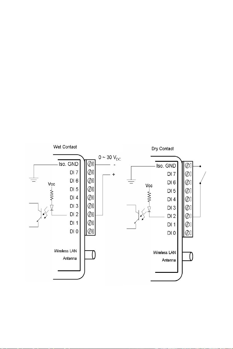
4.2.3 ADAM-6052
16-ch Source Type Isolated Digital Input/Output Module
The ADAM-6052 is a high-density digital I/O module built-in a 10/100
based-T interface for seamless Ethernet connectivity. It provides 8 digital
input, 8 digital output channels. All of the digital input channels support
input latch function for important signal handling. The digital output
channels support the source type output. Meanwhile, these DI channels
allow to be used as 3 kHz counter and frequency input channels. Opposite
to the intelligent DI functions, the digital output channels also support
pulse output function.
ADAM-6052 Specifications
• Communication: 10/100 Base-T Ethernet
• Supports Protocol: Modbus/TCP, TCP/IP, UDP, HTTP, ICMP and ARP
• Supports Peer-to-Peer and GCL (Refer to Section 5.3.4 and Chapter 7)
Digital Input
• Channels: 8
• Dry Contact:
Logic level 0: Close to Ground
Logic level 1: Open
• Wet Contact:
Logic level 0: 0 ~ 3 VDC
Logic level 1: 10 ~ 30 VDC
• Supports 3 kHz counter input (32-bit + 1-bit overflow)
• Supports 3 kHz frequency input
• Supports inverted DI status
ADAM-6000 Series User Manual 42
Page 53

Digital Output
DI GND
DI 7
DI 6
DI 5
DI 4
DI 3
DI 2
DI 1
DI 0
RJ-45
(Ethernet)
DI_COM
DO_VCC
DO 0
DO 1
DO 2
DO 3
DO 4
DO 5
DO 6
DO 7
DO_GND
(R) +Vs
(B) GND
Dry Contact
• Channels: 8
• Source Type: 10 ~ 35 VDC, 1 A (per channel)
• Supports 5 kHz pulse output
• Supports high-to-low and low-to-high delay output
General:
• Built-in Watchdog Timer
• Isolation Protection: 2000 VDC
• Power Input: Unregulated 10 ~ 30 VDC
• Power Consumption: 2 W @ 24 VDC
• Power Reversal Protection
• Operating Humidity: 20 ~ 95 % RH (non-condensing)
• Storage Humidity: 0 ~ 95 % RH (non-condensing)
• Operating Temperature: -10 ~ 70° C
• Storage Temperature: -20 ~ 80° C
Application Wiring
Figure 4.17: ADAM-6052 DI (Dry Contact) Wiring
43 Chapter 4
Page 54

Figure 4.18: ADAM-6052 DI (Wet Contact) Wiring
DI GND
DI 7
DI 6
DI 5
DI 4
DI 3
DI 2
DI 1
DI 0
RJ-45
(Ethernet)
DI_COM
DO_VCC
DO 0
DO 1
DO 2
DO 3
DO 4
DO 5
DO 6
DO 7
DO_GND
(R) +Vs
(B) GND
Load
10 ~ 30 V
DC
Figure 4.19: ADAM-6052 Digital Output Wiring
ADAM-6000 Series User Manual 44
Page 55

Assigning Addresses for ADAM-6052 Modules
Based on Modbus/TCP, the addresses of the I/O channels in ADAM-6000
modules are defined by a simple rule. Please refer to Appendix B.2.7 to
map the I/O address. All digital input channels in ADAM-6052 are
allowed to use as 32-bit counters (Each counter is consisted of two
addresses, Low word and High word). Users could configure the specific
DI channels to be counters via Windows Utility. (Refer to Section 5.3)
4.2.4 ADAM-6060
6-ch Digital Input and 6-ch Relay Module
ADAM-6060 is a high-density I/O module with a 10/100 base-T interface
for seamless Ethernet connectivity. Bonding with an Ethernet port and
webpage, ADAM-6060 offers 6 relay (form A) output and 6 digital input
channels. It supports contact as AC 120V@0.5A, and DC 30V@1A. DI
channels support input latch for signal handling, and can be used as 3
KHz counter and frequency input channels. Opposite to the intelligent DI
functions, the DO channels also support pulse output.
ADAM-6060 Specifications
• Communication: 10/100 Base-T Ethernet
• Supports Protocols: Modbus/TCP, TCP/IP, UDP, HTTP, ICMP, ARP
• Supports Peer-to-Peer and GCL (Refer to Section 5.3.4 and Chapter 7)
Digital Input
• Channels: 6
• Dry Contact:
Logic level 0: Close to Ground
Logic level 1: Open
• Wet Contact:
Logic level 0: 0 ~ 3 VDC
Logic level 1: 10 ~ 30 VDC
• Support 3 kHz counter input (32-bit + 1-bit)
• Support 3 kHz frequency input
• Support inverted DI status
45 Chapter 4
Page 56

Relay Output
• Channels: 6 (Form A)
• Contact rating (Resistive):AC: 120 V @ 0.5 A
DC: 30 V @ 1 A
• Breakdown voltage: 500 VAC (50/60 Hz)
• Relay on time: 7 millisecond
• Relay off time: 3 millisecond
• Total switching time: 10 milliseconds
• Insulation Resistance: 1 G
minimum at 500 VDC
• Maximum Switching Rate: 20 operations/minute (at rated load)
• Electrical Endurance
At 12 V / 10 mA Typical 5 x 10
At 6 V / 100 mA Typical 1 x 10
At 60 V / 500 mA Typical 5 x 10
At 30 V / 1000 mA Typical 1 x 10
At 30 V / 2000 mA Typical 2 x 10
• Mechanical endurance Typical 10
7
operations
7
operations
5
operations
6
operations
5
operations
8
operations
• Supports pulse output (maximum 3 Hz)
General:
• Built-in Watchdog Timer
• Isolation Protection: 2000 VDC
• Power Input: Unregulated 10 ~ 30 VDC
• Power Consumption: 2 W @ 24 VDC
• Power Reversal Protection
• Operating Humidity: 20 ~ 95 % RH (non-condensing)
• Storage Humidity: 0 ~ 95 % RH (non-condensing)
• Operating Temperature: -10 ~ 70° C
• Storage Temperature: -20 ~ 80° C
ADAM-6000 Series User Manual 46
Page 57

Application Wiring
Figure 4.20: ADAM-6060 Digital Input Wiring
Figure 4.21: ADAM-6060 Relay Output Wiring
47 Chapter 4
Page 58

Assigning Addresses in ADAM-6060 Modules
Basied on Modbus/TCP standard, the addresses of the I/O channels in
ADAM-6000 modules are defined by a simple rule. Refer to Appendix
B.2.8 to map the I/O address. All digital input channels in ADAM-6060
are allowed to use as 32-bit counters (Each counter is consisted of two
addresses, Low word and High word). Users could configure the specific
DI channels to be counters via Windows Utility. (Refer to Section 5.3)
4.2.5 ADAM-6066
6-ch Digital Input and 6-ch Power Relay Module
ADAM-6066 is a high-density I/O module with a 10/100 base-T interface
for seamless Ethernet connectivity. ADAM-6066 offers 6 high voltage
power relay (form A) output and 6 digital input channels. It supports contact rating as AC 250V@5A, and DC 30V@3A. All of the digital input
channels support input latch function for signal handling. Meanwhile,
these DI channels can be used as 3 KHz counter and frequency input
channels. Opposite to the intelligent DI functions, the digital output channels also support pulse output function.
ADAM-6066 Specifications:
• Communication: 10/100 Base-T Ethernet
• Supports Protocol: Modbus/TCP, TCP/IP, UDP, HTTP, ICMP and ARP
• Supports Peer-to-Peer and GCL (Refer to Section 5.3.4 and Chapter 7)
Digital Input
• Channels: 6
• Dry Contact:
Logic level 0: Close to Ground
Logic level 1: Open
• Wet Contact:
Logic level 0: 0 ~ 3 VDC
Logic level 1: 10 ~ 30 VDC
• Supports 3 kHz counter input (32-bit + 1-bit)
• Supports 3 kHz frequency input
• Supports inverted DI status
ADAM-6000 Series User Manual 48
Page 59

Relay Output
• Channels: 6 (Form A)
• Contact rating (Resistive): AC: 250 V @ 5 A
DC: 30 V @ 3 A
• Breakdown voltage: 500 VAC (50/60 Hz)
• Relay on time: 7 millisecond
• Relay off time: 3 millisecond
• Total switching time: 10 milliseconds
• Insulation Resistance: 1 G
minimum at 500 VDC
• Maximum Switching Rate: 20 operations/minute (at rated load)
• Electrical Endurance
At 30 VDC / 3 A Typical 1 x 10
5
operations
(Operating frequency 20 operations/minute)
At 250 VAC / 3 A Typical 1 x 10
5
operations
(Operating frequency 20 operations/minute)
• Mechanical endurance Typical 2 x 10
7
operations
(Under no load at operating frequency of 180 operations/minute)
• Supports pulse output (maximum 3 Hz)
General:
• Built-in Watchdog Timer
• Isolation Protection: 2000 VDC
• Power Input: Unregulated 10 ~ 30 VDC
• Power Consumption: 2.5 W @ 24 VDC
• Power Reversal Protection
• Operating Humidity: 20 ~ 95 % RH (non-condensing)
• Storage Humidity: 0 ~ 95 % RH (non-condensing)
• Operating Temperature: -10 ~ 70° C
• Storage Temperature: -20 ~ 80° C
49 Chapter 4
Page 60

Application Wiring
Figure 4.22: ADAM-6066 Digital Input Wiring
Figure 4.23: ADAM-6066 Relay Output Wiring
ADAM-6000 Series User Manual 50
Page 61

4.2.6 ADAM-6050W
18-ch Wireless Isolated Digital Input/Output Module
ADAM-6050W is a high-density I/O module with a IEEE 802.11b wireless LAN interface for seamless Ethernet connectivity. It provides 12 digital input and 6 digital output channels with 2000 VDC isolation
protection. All DI channels support input latch function for important signal handling. Meanwhile, the DI channels can be used as 3 kHz counter
and frequency input channels. In addition to the intelligent DI functions,
the digital output channels also support pulse output functionality.
ADAM-6050W Specifications
• Communication: IEEE 802.11b Wireless LAN
• Supports Protocol: Modbus/TCP, TCP/IP, UDP, HTTP, ICMP and ARP
• Supports Peer-to-Peer (Refer to Section 5.3.4)
Digital Input
• Channels: 12
• Dry Contact:
Logic level 0: Close to Ground
Logic level 1: Open
• Wet Contact:
Logic level 0: 0 ~ 3 VDC
Logic level 1: 10 ~ 30 VDC
• Support 3 kHz counter input (32-bit + 1-bit)
• Support 3 kHz frequency input
• Support inverted DI status
Digital Output
• Channels: 6
• Sink type: Open Collector to 30 V, 100 mA (maximum load)
• Supports 5 kHz pulse output
• Supports high-to-low and low-to-high delay output
51 Chapter 4
Page 62

General:
• Built-in Watchdog Timer
• Isolation Protection: 2000 VDC
• Power Input: Unregulated 10 ~ 30 VDC
• Power Consumption: 2 W @ 24 VDC
• Power Reversal Protection
• Operating Humidity: 5 ~ 95 % RH (non-condensing)
• Storage Humidity: 5 ~ 95 % RH (non-condensing)
• Operating Temperature: -10 ~ 60° C
• Storage Temperature: -20 ~ 80° C
Application Wiring
Figure 4.24: ADAM-6050W Digital Input Wiring
ADAM-6000 Series User Manual 52
Page 63

Figure 4.25: ADAM-6050W Digital Output Wiring
4.2.7 ADAM-6051W
14-ch Wireless Isolated Digital Input/Output w/2-ch Counter Module
ADAM-6051W is a high-density I/O module with an IEEE 802.11b
wireless LAN interface for seamless Ethernet connectivity. It provides 12
digital inputs, 2 digital outputs, and 2 counter channels with 2000 VDC
isolation protection. All of digital input channels support input latch functionality for important signal handling. Meanwhile, these DI channels can
be used as 3 kHz counter and frequency input channels. In addition to the
intelligent DI functions, the digital output channels also support pulse
output functionality.
ADAM-6051W Specifications
• Communication: IEEE 802.11b Wireless LAN
• Supports Protocol: Modbus/TCP, TCP/IP, UDP, HTTP, ICMP and ARP
• Supports Peer-to-Peer (Refer to Section 5.3.4)
53 Chapter 4
Page 64

Digital Input
• Channels: 12
• Dry Contact:
Logic level 0: Close to Ground
Logic level 1: Open
• Wet Contact:
Logic level 0: 0 ~ 3 VDC
Logic level 1: 10 ~ 30 VDC
• Supports 3 kHz counter input (32-bit + 1-bit)
• Supports 3 kHz frequency input
• Supports inverted DI status
Counter Input
• Channels: 2 (32-bit + 1-bit overflow)
• Maximum count: 4,294,967,295
• Frequency range: 0.2 ~ 4500 Hz (frequency mode)
0 ~ 4500 Hz (counter mode)
Digital Output
• Channels: 2
• Sink type: Open Collector to 30 V, 100 mA (maximum load)
• Supports 5 kHz pulse output
• Supports high-to-low and low-to-high delay output
ADAM-6000 Series User Manual 54
Page 65
General:
• Built-in Watchdog Timer
• Isolation Protection: 2000 VDC
• Power Input: Unregulated 10 ~ 30 VDC
• Power Consumption: 2.5 W @ 24 VDC
• Power Reversal Protection
• Operating Humidity: 5 ~ 95 % RH (non-condensing)
• Storage Humidity: 5 ~ 95 % RH (non-condensing)
• Operating Temperature: -10 ~ 60° C
• Storage Temperature: -20 ~ 80° C
Application Wiring
Figure 4.26: ADAM-6051W Digital Input Wiring
55 Chapter 4
Page 66

Figure 4.27: ADAM-6051W Counter (Frequency)
Figure 4.28: ADAM-6051W Digital Output Wiring
ADAM-6000 Series User Manual 56
Page 67

4.2.8 ADAM-6060W
6-ch Wireless Digital Input and 6-ch Relay Module
ADAM-6060W is a high-density I/O module with a built-in
IEEE802.11b wireless LAN interface for seamless Ethernet connectivity.
With an Ethernet port and embedded web server, ADAM-6060W offers 6
relay (form A) outputs and 6 digital input channels. It supports contact
ratings of AC 120V @ 0.5A, and DC 30V @ 1A. All the digital input
channels support input latch functionality for critical handling. Also,
these DI channels can be used as 3 kHz counter and frequency input
channels. In addition to the intelligent DI functions, the digital output
channels support pulse output.
ADAM-6060W Specifications
• Communication: IEEE 802.11b Wireless LAN
• Supports Protocol: Modbus/TCP, TCP/IP, UDP, HTTP, ICMP and ARP
• Supports Peer-to-Peer (Refer to Section 5.3.4)
Digital Input
• Channels: 12
• Dry Contact:
Logic level 0: Close to Ground
Logic level 1: Open
• Wet Contact:
Logic level 0: 0 ~ 3 VDC
Logic level 1: 10 ~ 30 VDC
• Support 3 kHz counter input (32-bit + 1-bit)
• Support 3 kHz frequency input
• Support inverted DI status
57 Chapter 4
Page 68

Relay Output
• Channels: 6 (Form A)
• Contact rating (Resistive): AC: 120 V @ 0.5 A
DC: 30 V @ 1 A
• Breakdown voltage: 500 VAC (50/60 Hz)
• Relay on time: 7 millisecond
• Relay off time: 3 millisecond
• Total switching time: 10 milliseconds
• Insulation Resistance: 1 G
minimum at 500 VDC
• Maximum Switching Rate: 20 operations/minute (at rated load)
• Electrical Endurance
At 12 V / 10 mA Typical 5 x 10
At 6 V / 100 mA Typical 1 x 10
At 60 V / 500 mA Typical 5 x 10
At 30 V / 1000 mA Typical 1 x 10
At 30 V / 2000 mA Typical 2 x 10
• Mechanical endurance Typical 1 x 10
7
operations
7
operations
5
operations
6
operations
5
operations
8
operations
• Supports pulse output (maximum 3 Hz)
General:
• Built-in Watchdog Timer
• Isolation Protection: 2000 VDC
• Power Input: Unregulated 10 ~ 30 VDC
• Power Consumption: 2 W @ 24 VDC
• Power Reversal Protection
• Operating Humidity: 5 ~ 95 % RH (non-condensing)
• Storage Humidity: 5 ~ 95 % RH (non-condensing)
• Operating Temperature: -10 ~ 60° C
• Storage Temperature: -20 ~ 80° C
ADAM-6000 Series User Manual 58
Page 69

Figure 4.29: ADAM-6060W Digital Input Wiring
Iso. GND
RL 5-
RL 5+
DI 5
DI 4
DI 3
DI 2
DI 1
DI 0
RL 0+
RL 0RL 1+
RL 1-
RL 2+
RL 2RL 3+
RL 3-
RL 4+
RL 4-
N/A
(R) +Vs
(B) GND
120 VAC, 30 V
DC
L
~
Wireless LAN
Antenna
Figure 4.30: ADAM-6060W Relay Output Wiring
59 Chapter 4
Page 70

Note: Normal/Diag Switch
At one side of ADAM-6000W modules (ADAM6050W, ADAM-6051W and ADAM-5060W),
there is one Normal/Diag switch. When you set
that switch to the “Diag” end for diagnostic
mode, all related setting listed below will
become default value:
IP: 10.0.0.1
Password: 00000000
WEP: Off
SSID: WLAN for Ad-hoc mode
<ANY> for Infrastructure mode
Channel: 10
When you set that switch to “Normal” end for
normal mode, you can set the setting listed
above to the value you want. It is helpful to
change to diagnostic mode when you have
trouble to use your module.
ADAM-6000 Series User Manual 60
Page 71

2
5
CHAPTER
System
Configuration Guide
Sections include:
• System Hardware Configuration
• Install ADAM.NET Utility Software
• ADAM.NET Utility Overview
• Java Applet Customization
• Appendix A
Page 72

Chapter 5 System Configuration Guide
5.1 System Hardware Configuration
As we mentioned in Chapter 3-1, you will need following items to complete your system hardware configuration.
5.1.1 System Requirements
Host Computer
• IBM PC compatible computer with 486 CPU (Pentium recommended)
• Microsoft 98/2000/XP/Vista or higher versions
• At least 32 MB RAM
• 20 MB of hard disk space available
• VGA color monitor
• 2x or higher speed CD-ROM
• Mouse or other pointing devices
• 10 or 100 Mbps Ethernet Card
5.1.2 Communication Interface
• 10/100 Mbps Ethernet hub (at least 2 ports) and two Ethernet cables
with RJ-45 connector
• Wireless Access Point when you are using ADAM-6000W modules
• Crossover Ethernet cable with RJ-45 connector
5.2 Install ADAM.NET Utility Software
Advantech provides a free download of ADAM.NET Utility software for
ADAM-6000 modules operation and configuration. You can find the Utility installation file in the CD with your ADAM module, or link to the web
site: http://www.advantech.com and click into the Download Area under
Service & Support site to get the latest version of the ADAM-6000 Series
ADAM.NET Utility. Once you download and setup the Utility software,
there will be a shortcut of the Utility program on the desktop.
Note: Before installing ADAM.NET Utility, you need to install
.NET Framework 1.1 or later.
ADAM-6000 Series User Manual 62
Page 73

5.3 ADAM.NET Utility Overview
Module Tree Display
Area
Status Display Area
Menus
Toolbar
The ADAM.NET Utility software offers a graphical interface that helps
you configure the ADAM-6000 modules. It is also very convenient to test
and monitor your remote data acquisition and control system. The following guidelines will give you some brief instructions on how to use this
Utility.
5.3.1 ADAM.NET Utility Operation Window
After you have successfully installed ADAM.NET Utility, there will be
one shortcut icon on the desktop. Double click the shortcut icon that you
should be able to see the operation window as Figure 5.1.
The operation window consists of four areas --- the Menus, the Toolbar,
the Module Tree Display Area and the Status Display Area.
Figure 5.1: ADAM.NET Utility Operation Window
63 Chapter 5
Page 74

Menus
The menus at the top of the operation window contain:
File Menu:
1. Open Favorite Group - You can configure your favorite group and
save the configuration into one file. Using this option, you can load
your configuration file for favorite group.
2. Save Favorite Group - You can configure your favorite group and
save the configuration into one file. Using this option, you can save
your favorite group into one configuration file.
3. Auto-Initial Group - If you want to have the same favorite group
configuration when you exit ADAM.NET utility and launch it
again, you need to check this option.
4. Exit - Exit ADAM.NET Utility.
Tools Menu:
1. Search - Search all the ADAM-6000 and ADAM-5000/TCP mod-
ules you connected. The operation process will be described in Section 5.3.2.
2. Add Devices to Group - You can add ADAM-6000 modules to your
favorite group by this option. You need to select the device you
want to add in the Module Tree Display area (it will be described
below) first, and then select this option to add.
3. Terminal for Command Testing - ADAM-6000 modules support
ASCII command and Modbus/TCP as communication protocol.
You can launch the terminal to communicate with ADAM-6000
module by these two protocol directly. (Refer to Section 6.3 and 6.4
for more information about ASCII and Modbus/TCP command.)
4. DiagAnywhere Searcher - There are multiple Advantech products
installed with DiagAnywhere server, which gives user remote control ability through Ethernet. When you choose this option, all
devices with DiagAnywhere server in the Ethernet you connected
with will be listed.
5. Print Screen - You can save current ADAM.NET Utility screen into
an image file by this option.
ADAM-6000 Series User Manual 64
Page 75

6. Monitor Stream/ Adam5000 Event Data - ADAM-6000 modules
support Data Stream function. You can define the Host (such as a
PC) by IP. Then ADAM-6000 modules will periodically send its I/
O status to the Host. The IP and period to transfer data is configured in the Stream tab of Status Display area. The configuration
tab will be introduced in Section 5.3.2.
Note: When you enable GCL function, Data Stream function will
automatically be disabled until you disable GLC function.
7. Monitor Peer-to-Peer (Event Trigger) - ADAM-6000 modules with
Peer-to-Peer function can play as Event Trigger function. Refer to
Section 5.3.4 for more information. You can choose this option to
receive message from ADAM-6000 module which is enabled Peerto-Peer (Event Trigger) function.
8. Monitor GCL IO Data Message - ADAM-6000 modules with GCL
function can play as a standalone controller. Users can define logic
rules and run the rules on ADAM-6000 module. User can define
the logic rule to send out message, depending on the logic condition, to the Host defined by IP. Refer to Chapter 7 for more information about GCL. You can choose this option to receive I/O data
message from ADAM-6000 module which is enabled GCL function.
Setup Menu:
1. Favorite Group - You can configure your favorite group including
add one new device, modify or delete one current device, sort current devices and diagnose connection to one device.
2. Refresh COM and LAN node - ADAM.NET utility will refresh the
serial and LAN network connection situation.
3. Add COM Port Tree Nodes - This option is used to add serial COM
ports in ADAM.NET Utility. You won't need to use this option for
ADAM-6000 modules.
4. Show TreeView - Check this option to display the Module Tree
Display area.
65 Chapter 5
Page 76

Help Menu:
Open Favorite Group
Save Favorite Group
Search Modules
Add Devices to Group
Terminal for Command Testing
Monitor Stream/Event Data
Print Screen
1. Check Up-to-Date on the Web - Choose this option, it will automat-
ically connect to Advantech download website.You can download
the latest utility there.
2. About Adam.NET Utility - Choose this option, you can see version
of ADAM.NET Utility installed on your computer.
Toolbar
There are 7 graphical icons on the toolbar for 7 common used options of
Menus. Figure 5.2 below shows definition for each graphical icon.
Figure 5.2: ADAM.NET Utility Toolbar
Module Tree Display Area
ADAM.NET Utility is one complete software tool that all ADAM remote
I/O module and controller can be configured and operated in this utility.
The Module Tree Display is on the left part of the utility operation win-
dow. There are four categories in the Module Tree Display Area:
• ADAM4000_5000
All serial I/O Modules (ADAM-4000 and ADAM-5000 RS-485 serial
modules) connected to the host PC will be listed in this category.
• ADAM5000TCP_6000
All Ethernet I/O Modules (ADAM-6000 and ADAM-5000 TCP
modules) connected to the host PC will be listed in this category.
• ADAM-4500_5510Series
This is a DOS interface utility for remote controllers such as ADAM4500 and ADAM-5510 series.
ADAM-6000 Series User Manual 66
Page 77

• Favorite Group
You can define which devices listed in the three categories above into
your personal favorite group. This will make you easier to find your interested modules. Right click on the ADAM device item under the Favorite
Group item and you can select New >> Group to create a new group.
After you create your own group, right click on your group and select
New >> Adam device to add ADAM devices into your group. You can
also select Diagnose connection to check the communication.
Note: Remember to choose the correct module in the Module
Type combo box when you add a new ADAM devices.
Status Display Area
Status Display area, on the right part of utility operation window, is the
main screen for operation. When you select different items in Module
Tree Display, Status Display will change dependently. You can do all
configurations and test in this area.
5.3.2 Search ADAM-6000 Modules
After you have confirmed the hardware wiring between host PC and your
ADAM-6000 module, you can find that module in ADAM.NET Utility.
Launch ADAM.NET Utility. Select the ADAM5000TCP_6000 item on
the Module Tree Display area. Click the Search Modules button on the
Toolbar. ADAM.NET Utility will then search all ADAM-6000 modules
on the Ethernet network. If your ADAM-6000 modules is used the first
time, its IP will be 10.0.0.1 by default. So you will find it showing on the
Others item under ADAM5000TCP_6000.
Note: If network Firewall is enabled on your computer, you
may not be able to connect with your ADAM-6000 module. You need to add ADAM.NET Utility into lists of Program and Service of the Exception for Windows Firewall
in Windows Control Panel.
You need to change IP of the ADAM-6000 modules the same subnet with
the host PC. Type the correct IP address, Subnet address, and Default
gateway on the Status Display area. After complete setting, click the
Apply Change button. A dialog box appears asking you to type the pass-
word. The default password of ADAM-6000 module is 00000000.
67 Chapter 5
Page 78

You can change the password later. After you type the correct password,
the ADAM-6000 module is now under IP of your host PC.
When you select the IP address of the ADAM-6000 modules you want
use in Module Tree Display area, there will be 8 tabs appearing in the
Status Display area for you to set up general configuration of that module. Refer to figure below. Once you have changed any configuration,
remember to click related Apply or Apply Change button.
Below is detailed information for the 8 tabs in the Status Display area:
Information
You can see the Firmware Version on the selected ADAM-6000 module
in this tab. You also can change the Device Name and Device Descrip-
tion. When you have several ADAM-6000 modules in the same network,
it is helpful to identify your interested ADAM-6000 modules using specific device name and device description.
ADAM-6000 Series User Manual 68
Page 79

Network
If necessary, you still can change IP Address, Subnet Address, and
Default Gateway of selected ADAM-6000 module in this tab. The Host
Idle (Timeout) text box is used for TCP connection timeout. The maxi-
mum number of TCP connections of one ADAM-6000 module is 8. Any
application using TCP to communicate with the ADAM-6000 module
will occupy at least one connection. If there is no communication for one
connection after a specific timeout interval, ADAM-6000 module will
close that connection and release it to others. Without this feature, when
the number of TCP connection exceeds the maximum number (namely
8), no more other application can connect to the ADAM-6000 modules.
Note: When you use web browser to open the web page on
Adam-6000, the JVM (Java Virtual Machine) will use
several TCP connections mentioned above to download .jar file. Those connections will be released after
the .jar file is downloaded completely.
RS-485/WDT
This tab is used for ADAM-5000/TCP module. You don't need to use this
tab for ADAM-6000 modules.
Stream
ADAM-6000 modules can actively send its data to Hosts periodically. It
is called Data Stream. In this tab, you can define IP address of the Hosts
receiving the data transferred by ADAM-6000 modules, as well as the
period how often ADAM-6000 modules will send data to the Hosts.
Note: Set the period by Data Streaming tab at right. ADAM-5000/TCP
Event Trigger tab is for ADAM-5000.
Note: When you enable GCL function, Data Stream function will automatically be disabled until you disable GLC function.
69 Chapter 5
Page 80

Password
In this tab, you can set up password for selected ADAM-6000 module.
You need to type current password in the Old password text box, and the
new password in the New password and Verify password text box.
There will be many configuration and operation action asking user to type
password, so this can help to ensure safety.
Note: The default password is 00000000
Firmware
Advantech will continuously release new version of firmware to add or
improve functionality of ADAM-6000 modules. You can connect to the
Advantech website (http://www.advantech.com) to download the latest
version of firmware. There should be three files with different file extension: .bin, .html and .jar. The file with .bin extension is the firmware
itself. And the two files with .html and .jar extension are for the Web
Server on the ADAM-6000 module. In this tab, you can upgrade the
downloaded firmware to your ADAM-6000 module. Click the Open button to load the three firmware files from your computer. Then click
Upgrade button to download the firmware to the ADAM-6000 module.
Note: When you update a new firmware to your module, some
of the configurations for the 8 tabs in the Status Display
area may be changed. We suggest you to confirm the
configurations again.
Note: ADAM-6024 doesn't support webpage upgrade
(.html and .jar file).
Peer-to-Peer /Event
You can enable and configure Peer-to-Peer (Event) function in this tab.
For more detail about Peer-to-Peer (Event) function, refer to section
5.3.4.
ADAM-6000 Series User Manual 70
Page 81

Access Control
You can decide which computers or devices have the ability to control
this ADAM-6000 module in this tab. Select the IP Address or MAC
Address radio button to decide the identified method, and then click the
Apply button. In the Security IP/MAC Setting area, you can direct type
the IP or MAC address of the authorized computers or devices. Remember to click the Enable/Disable check box, meaning that IP or MAC
address is selected. Take Figure 5.3 as example, only the computer (or
device) with IP Address 172.18.3.52 or 172.18.3.116 can have the authority to control this ADAM-6000 module. If there is no check box selected,
it means there is no security limitation that any computer or device can
control the ADAM-6000 modules. After completing typing all IP or
MAC address, click Apply or Apply all button.
Figure 5.3: Access Control Setting
71 Chapter 5
Page 82

5.3.3 I/O Module Configuration
All Channel Con figuration
Individual Channel Configuration
GCL Configuration
After you have completed all general configuration of ADAM-6000 module described in previous section, then you need to configure setting for
input and output channel such as channel range, calibration and alarm. At
the same time, you can see input channel value and set value of output
channel in the Status Display area of utility. In the Module Tree Display
area, click the item showing IP of the ADAM-6000 modules you want to
use. There will be two items appearing below the IP: All Channel Con-
figuration and GCL Configuration item. Refer to Figure 5.4 below.
(The related feature of GCL item will be described in Chapter 7)
Click the cross icon besides the All Channel Configuration item, one
dialog window will appear to ask you typing password. After you enter
the correct password, Individual Channel Configuration items will
appear below the All Channel Configuration item.
Figure 5.4: Channel & GCL Configuration
ADAM-6000 Series User Manual 72
Page 83

If you click the All Channel Configuration item, you can read analog
input value or configure setting for all channels on the Status Display
area. If you click the Individual Channel Configuration item, you can
read AI values or configure setting for the specific channel you choose.
Below, we will describe the All Channel Configuration and Individual
Channel Configuration in more detail for ADAM-6000 I/O modules.
• Analog Input Module (ADAM-6015, ADAM-6017 and ADAM-6018)
All Channel Configuration
For these ADAM-6000 modules, when you click the All Channel Configuration item in the Module Tree Display area, there will be four parts
on the Status Display area. In the top left-hand corner is the Channels
Range Configuration area. You can set different range for each channel.
In the Channels Range Configuration area, select the channel number
in the Channel index combo box, and then select the range in the Input
range combo box. After selecting appropriate range, click the Apply button. Refer to Figure 5.5 below.
Figure 5.5: Channels Range Configuration Area
73 Chapter 5
Page 84

In order to remove the noise from the power supply, these analog input
modules feature built-in filter. Two filters with different frequencies are
provided to remove noise generated from different power supplies. The
Integration Time Configuration area is under the Channels Range
Configuration area. Refer to Figure 5.6 below. In the Integration Time
Configuration area, you can select suitable filter in the Integration time
combo box. After selecting appropriate filter, click the Apply button.
Figure 5.6: Integration Time Configuration Area
In the top right-hand corner of the Status Display area is the Calibration
area. You can choose the Zero Calibration button to do zero calibration.
After you click the button, a pop-up dialog window will remind you to
connect a signal with minimum value of full scale range (for example, 0
Volt) to the calibrated channel. After you complete the hardware wiring,
click the Apply button to start the calibration action. Similarly, you can
choose the Span Calibration button to do span calibration. For span calibration, you need to connect a signal with maximum value of full scale
range (for example, 10 Volt) to the calibrated channel. It is the same that
when you complete the wiring, click the Apply button to start the calibration action.
ADAM-6000 Series User Manual 74
Page 85

At the bottom of the Status Display area, you can see five tabs to see ana-
log input value of all channels:
1. Channel Setting
You can see the current value of analog input on this tab. (For ADAM6017 and ADAM-6018 modules, the value of digital input channel is also
displayed on this tab.) Simply choose the check box of the channels you
want to monitor and click the Apply button.
Besides, you can see the graphical historical trend by clicking the Trend
Log button. Refer to Figure 5.7 below. Simply choose the check box of
the channels you want to log in the Channel Setting area at right side,
and then click the Apply button. After that, click the Start button and the
data log will start. You can see the real-time historical trend. If you click
the Stop button, then you can click the Save to file to save the trend data
into your computer.
Figure 5.7: Analog Input Trend Log
With the wire burn-out detection function of ADAM-6015 and
ADAM-6018, if there is no sensor connected to the input channel of
ADAM-6015 or ADAM-6018 module, you can see “Burn out” characters
showing in the text box of related channel.
75 Chapter 5
Page 86

2. Average Setting
ADAM-6015, ADAM-6017 and ADAM-6018 modules feature averaging
calculation function by its built-in processor. You can simply click the
check boxes representing the channels in the Averaging channel setting
area to decide which channels are used for averaging. For example, by
Figure 5.8 below, five channels (channel 0, 1, 2, 3, and 4) are used for
averaging. So you can see the average value of those five channels displayed by the Average text box.
Figure 5.8: Analog Input Average Setting
3. Modbus (Current)
You can see current analog input value in decimal, hexadecimal, and
engineer unit for all related Modbus address.
4. Modbus (Max)
ADAM-6015, ADAM-6017 and ADAM-6018 modules feature historical
maximum value recording. You can see historical maximum analog input
value in decimal, hexadecimal, and engineer unit for all related Modbus
address. To re-initialize the recording, click the buttons representing the
channels you want to reset.
ADAM-6000 Series User Manual 76
Page 87

5. Modbus (Min)
ADAM-6015, ADAM-6017 and ADAM-6018 modules feature historical
minimum value recording. You can see historical minimum analog input
value in decimal, hexadecimal, and engineer unit for all related Modbus
address. If you want to re-initialize the recording, click the buttons representing the channels you want to reset.
Individual Channel Configuration
You can see analog input value and configure setting for each channel.
Simply click one of the Individual Channel Configuration items for the
interested channel. (The average channel you set in the Averaging set-
ting will also be displayed here) At the upper part of the Status Display
area, you can see the current analog input value and defined range of that
channel by the Input value and Input range text box. Refer to Figure 5.9
below.
Figure 5.9: Analog Input Alarm Mode Configuration
77 Chapter 5
Page 88

ADAM-6015, 6017 and 6018 modules all feature built-in alarm function.
At the lower part of the Status Display area, there are two tabs to configure the high alarm and low alarm for the selected channel: High alarm
and Low alarm. When the analog input value is higher than the high
alarm value, or lower than the low alarm value, the alarm condition
occurs. Then the alarm status will be activated to logic high. For ADAM6015 module, ADAM.NET Utility can detect the alarm status and show it
by the Alarm status LED display. For ADAM-6017 and ADAM-6018
module, when the alarm condition occurs, the Alarm status LED display
will be lit. Besides, the specified digital output channel will generate
logic high value if you build the mapping relationship between alarm and
DO channel in the DO mapping area. You can set the DO channel by
Channel combo box in the DO mapping area. After choosing the interested channel, click the Apply button.
There are three alarm modes. You can select the alarm mode by the
Alarm mode combo box for the low alarm and high alarm respectively.
1. Disable: Alarm is disabled. So even when the alarm condition
occurs, nothing will happen.
2. Latch: Once the alarm condition occurs, the alarm status will be
activated to logic high level and will keep the value until the alarm
is clear manually. Before the value is clear, the Alarm status LED
will continuously be lit. For ADAM-6017 and ADAM-6018 module, the specific output channel (chosen in the DO mapping area)
will continuously generate logic high value. You can clear the
alarm by click the Clear latch button.
3. Momentary: The alarm status will dynamically change depends on
if the alarm condition occurs. If the alarm condition occurs, the
alarm status will be logic high. If the alarm condition disappears,
the alarm status will be logic low. So not only the Alarm status
LED in the utility but also the specific digital output channel value
will change depend on the alarm condition.
After you choose the alarm mode for high alarm or low alarm, click the
Apply mode button. Then you can define the high alarm value or low
alarm value by entering the value in Alarm limit text box. After you
enter the alarm value, click the Apply limit button. Once you have configured the alarm mode and alarm value, you can leverage ADAM-6000
analog input alarm function.
ADAM-6000 Series User Manual 78
Page 89

• Universal Input and Output Module (ADAM-6024)
All Channel Configuration
ADAM-6024 module features analog input, analog output, digital input
and digital output. Click the All Channel Configuration item. In the
Status Display area, there will be two tabs: Input and Output. On the
Input tab, there are still four parts on the Status Display area, which is
the same as ADAM-6015, ADAM-6017 and ADAM-6018 module. All
the configurations in the Channels Range Configuration, Integration
Time Configuration and Calibration areas are just the same as the configuration of ADAM-6015, ADAM-6017 and ADAM-6018 module.
Refer to Figure 5.10 below.
Figure 5.10: ADAM-6024 Input Tab
However, at the bottom of the Status Display area, there are only two
tabs to see analog input value of all channels: (This is because ADAM6024 doesn’t feature averaging, maximum and minimum calculation
function)
79 Chapter 5
Page 90

1. Channel Setting
You can see the current value of analog input on this tab. Choose the
check box of the analog input channels you want to monitor and click the
Apply button. If the analog input value is out of the input range, you will
see “Over(L)” in the analog input value text box. At the right side, you
can see current digital input value by DI 0 and DI 1 LED display.
You also can see the graphical historical trend of analog input channel by
clicking the Tre nd Log button. All the operations for trend logging is the
same as ADAM-6015, ADAM-6017 and ADAM-6018 module.
2. Modbus
You can see current analog input value in decimal and hexadecimal for all
related Modbus address.
On Output tab, you can write value to analog and digital output channel,
as well as configure all related setting. There are also two tabs on the Output tab: Channel setting and Modbus. Refer to Figure 5.11 below.
Figure 5.11: ADAM-6024 Output Tab
ADAM-6000 Series User Manual 80
Page 91

1. Channel Setting
Similar to analog input configuration, you can set different range for each
analog output channel. Select the channel number in the Channel index
combo box, and then select the range in the Output range combo box.
After selecting appropriate range, click the Apply button.
At the bottom left-hand corner of the Output tab, you can define the analog output value by using the horizontal pointer slide or the Value to Out-
put text box. After you have chosen the appropriate analog output value,
click the Apply output button.
Besides, you can set the startup value of the specific analog output channel. (The analog output channel will generate the startup value output
when it is power-on. In other words, start-up value can be considered as a
power-on value.) Use the horizontal slider or the Val u e to ou tp ut text
box to define the value and click Apply button. Then click the Set as
startup button to save that value as startup value.
At the bottom right-hand corner of the Output tab, it is Calibration area.
There are two buttons used to calibrate the maximum and minimum value
of full range. The label on the buttons will change depending on the output range. Take figure 5.11 as example, labels on the two buttons are
Trim for 4 mA (calibrate for minimum value of full range) and Trim f o r
20 mA (calibrate for maximum value of full range).
After you click one of the buttons, one dialog window will appear. Use
another instrument to measure the output value. Then use the four buttons
(-10, -1, +1, +10) on the dialog window to correct the analog output
value. For example, if you click the Tri m for 4 mA button, the specific
analog output channel should generate 4 mA. However, the instrument
reads 3.88 mA. So you need to use +1 and +10 button to adjust the output
value, until the output value is truly 4 mA.
In the top right-hand corner of the Output tab, you can control the digital
output value by the DO 0 and DO 1 button. Their value will be display by
the LED near the button.
81 Chapter 5
Page 92

2. Modbus
You can see current output value in decimal and hexadecimal for all
related Modbus address.
• Digital Input and Output Modules
(ADAM-6050, ADAM-6051, ADAM-6052, ADAM-6060, ADAM6066, ADAM-6050W, ADAM-6051W, and ADAM-6060W)
All Channel Configuration
When you click the All Channel Configuration item in the Module
Tree Display area, there will be two tabs: Channel Setting and Modbus.
Take ADAM-6050 as example. Refer to Figure 5.12 below:
Figure 5.12: ADAM-6050 Channel Setting
1. Channel Setting
You can see value of all digital input channels by related LED display in
this tab. Besides, you also can control values of all digital output channels
by related button. The LED next to the button will display current value
of that digital output channel.
ADAM-6000 Series User Manual 82
Page 93

When the communication between host PC and ADAM-6000 digital
modules is broken, the digital output channel can generate a predefined
value (this value is called fail safe value). You can enable or disable this
function by click the Turn on WDT checked channel when WDT trig-
gered check box. You can define the fail safe value by the WDT check
box next to the DO status LED. After configure related setting, click the
Apply WDT button. Take Figure 5.13 below as example. The fail safe
value function is enabled. If the communication between ADAM-6000
digital module and host PC is broken, channels 0 and 2 will automatically
generate logic high value, while channels 1, 3, 4, 5 will automatically
generate logic low value.
Figure 5.13: Fail Safe Value Configuration
2. Modbus
You can see current digital input or digital output values for all related
Modbus address.
Individual Channel Configuration
You can see digital input value and configure setting for each digital input
channel. It is the same that you can control the digital output value and
configure setting for each digital output channel. Simply click the channel
interested in the Individual Channel Configuration items.
If you choose a digital input channel, the Status Display area should look
similar to Figure 5.14 below.
83 Chapter 5
Page 94

Figure 5.14: Individual Channel Configuration: DI
You can choose different mode for that digital input channel by choosing
the DI mode combo box at top of Status Display area. (You should
choose the appropriate mode depending on the hardware specification.)
After you have chosen the mode, click the Apply mode button. There are
a total of five possible DI modes you can choose:
1. DI
Figure 5.14 is the image when you choose DI mode. At the bottom of the
Status Display area, you can see the digital input value by DI status
LED display. If the digital module you are using supports Invert DI Status
function, there will be Invert signal check box in the Setting area. You
can click the check box to enable or disable that function. Remember to
click the Apply all button for all channels or Apply this button for this
specific channel to complete the configuration. When you enable the
Invert DI Status function, the ADAM-6000 digital module will automatically inverse the digital input value. For example, if the real external signal value is logic level low, then the DI status LED display will be lit.
All ADAM-6000 digital modules support digital filter, so you can enable
or disable the filter by click the Enable digital filter check box. If you
enable the filter, you can define the minimum acceptable signal width by
the Minimum low signal width and Minimum high signal width text
box. (Unit: ms) The high frequency noise will be removed by this filter.
Remember to click the Apply all button for all channels or Apply this
button for this specific channel to complete the configuration.
ADAM-6000 Series User Manual 84
Page 95

2. Counter
When you choose Counter mode, one counter will count the pulse number of the digital signal from the selected channel, and then record the
count number in the register. The image of the Status Display area looks
similar as that of DI mode. At the bottom of the Status Display area, current count value of the selected channel is displayed by the Counter
value text box. You can start or stop the counter to count by clicking the
Star/Stop button next to the Counter value text box. You also can reset
the counter (the value in the register will be initialized to zero) by clicking the Clear button.
Like the DI mode, you can enable/disable the Invert DI Status function
and digital filter in the Setting area. The operation is the same. There is
one extra setting that you can define if the counter should keep the last
value when ADAM-6000 digital module powers off. If you enable this
function, when the digital module powers off, the last value of counter
will be kept in the register. As the module powers on, the counter will
continuously count from that value. Without this function, when the module powers off, the counter will reset and the count value in the register
will be zero. You can enable or disable this function by clicking the Keep
last value when power off check box. Remember to click the Apply all
button for all channels or Apply this button for this specific channel to
complete the configuration.
3. Low to High Latch
When you choose Low to High Latch mode, once the digital input channel detects logic level changes from low to high, the logic status will be
keep as logic high. The logic status will remain the logic high, until you
clear latch manually. Then the logic status will back to logic low. The
logic status can be seen by the Latch status LED display at the bottom of
the Status Display area. You can clear latch by clicking the Clear latch
button. It is the same as DI mode that you can enable or disable the Invert
DI Status function in the Setting area. Remember to click the Apply all
button for all channels or Apply this button for this specific channel to
complete the configuration.
85 Chapter 5
Page 96

4. High to Low Latch
When you choose High to Low Latch mode, once the digital input channel detects logic level changes from high to low, the logic status will be
keep as logic low. The logic status will remain the logic low, until you
clear latch manually. Then the logic status will back to logic high. The
logic status can be seen by the Latch status LED display at the bottom of
the Status Display area. You can clear latch by clicking the Clear latch
button. It is the same as DI mode that you can enable or disable the Invert
DI Status function in the Setting area. Remember to click the Apply all
button for all channels or Apply this button for this specific channel to
complete the configuration.
5. Frequency
When you choose Frequency mode, ADAM-6000 digital module will calculate the frequency value of the digital input signal from the selected
channel. The frequency value will be displayed by the Frequency value
text box at the bottom of the Status Display area.
If you choose a digital output channel in the Individual Channel Config-
uration items, the Status Display area should look similar to Figure 5.15
below.
Figure 5.15: Individual Channel Configuration: DO
You can choose different mode for that digital output channel by choosing the DO mode combo box at top of Status Display area. (You should
choose the appropriate mode depending on the hardware specification.)
After you have chosen the mode, click the Apply mode button. There are
totally four possible DO modes you can choose:
ADAM-6000 Series User Manual 86
Page 97

1. DO
Figure 5.15 is the image when you choose DO mode. You can control the
digital output value of the selected channel by the DO button. The current
digital output value will be shown by the DO status LED display.
2. Pulse Output
The pulse output is the same as PWR. After you choose the Pulse output
mode, the selected digital output channel can generate continuous pulse
train or finite pulses. You can define the pulse width by entering into the
Low signal width and High signal width text box in the Setting area.
(Unit: 0.1 ms) The frequency and duty cycle of the pulse output signal
will be calculated automatically and displayed by the Output frequency
and Duty cycle text box. After you complete the setting, click the Apply
change button. Then you can choose to generate continuous pulse train or
finite pulses by selecting the Continuous (for pulse train) or the Fixed
total (for finite pulses) radio button. The text box at the right hand of the
Fixed total button is used to define how many pulses you want to gener-
ate. After select the pulse output mode, click the Start or Stop button to
generate or stop the pulse output.
3. Low to High Delay
When you choose Low to High delay mode, it is almost the same as
choosing the DO mode. The only difference is that there will be certain
time delay when the output value changes from logic low to logic high.
Refer to Figure 5.16 below for its process. You can define the delay time
by entering its value into the Delay time text box in the Setting area.
After you complete the setting, click the Apply button. Then you can
control the digital output value by the DO button and see its current value
by the DO status LED display at the bottom of the Status Display area.
87 Chapter 5
Page 98

At the moment that you write logic high
to the digital output channel
At the moment that you write logic low
to the digital output channel
Delay Time
At the moment that you wri te logic
high to the di gital output channel
At the moment that you write logic low
to the digi tal out put channel
Delay Time
Figure 5.16: Low to High Delay Output Mode
4. High to Low Delay
When you choose High to Low delay mode, it is almost the same as
choosing the DO mode. The only difference is that there will be certain
time delay when the output value changes from logic high to logic low.
Refer to Figure 5.17 below for its process. You can define the delay time
by entering its value into the Delay time text box in the Setting area.
After you complete the setting, click the Apply button. Then you can
control the digital output value by the DO button and see its current value
by the DO status LED display at the bottom of the Status Display area.
Figure 5.17: Low to High Delay Output Mode
ADAM-6000 Series User Manual 88
Page 99

5.3.4 Peer-to-Peer Function
• What is Peer-to-Peer?
When you want to send a signal from one module to another module,
Peer-to-Peer is a perfect solution. With Peer-to-Peer function enabled,
ADAM-6000 modules can actively update its input value to other devices
such as PC or another ADAM-6000 module. One typical application is
using a pair of ADAM-6000 modules. The value of input channel on one
module will be automatically updated to output channel on another module. The data will be transferred automatically as long as the connection
between the two ADAM-6000 modules is already built. No controller is
needed to take care of the communication. ADAM-6000 modules feature
two types of Peer-to-Peer function:
Note: Please use Ethernet Switch between a pair of Peer-to-
Peer modules. Do not use an Ethernet hub. This can
prevent data packet collision.
Note: ADAM-6000 modules support 2 features: Peer-to-Peer
(Event) and GCL (GCL will be introduced in Chapter 7). You
cannot enable these two features at the same time. So if
you has enabled GCL function before, and want to use
Peer-to-Peer (Event) function now, you need to disable GCL
function first. (See Section 7.2 for how to disable GCL)
Note: To utilize Peer-to-Peer function, you need to upgrade firm-
ware version of your ADAM-6000 module to 3.x or later.
1. Basic Mode:
For basic mode, there will be only one target device to receive the data
transferred from one ADAM-6000 module (Module A). Usually the target device is another ADAM-6000 module (Module B). The input channels of Module A will be mapping to the output channels of module B.
Meanwhile, value of all the input channels of module A will automatically update to output channels of module B. Of course, you can define
mask to disconnect relationship between some input and output channels.
89 Chapter 5
Page 100

2. Advanced Mode:
Channel 1
Channel 2
…..
Channel n
Channel 1
Channel 2
…..
Channel n
You can close the mapping relationsh
Channel 1
Channel 2
…..
Channel n
Module B
Channel 3
Module C
Channel 4
Module D
Channel 5
Module A
Module A
Channel 4
Module B
Channel 3
Module C
Channel 2
Channel 1
Channel 2
…..
Channel n
Module D
For advanced mode, there will be multiple target devices to receive the
data transferred from one ADAM-6000 module (Module A). For example, there can be several ADAM-6000 modules receiving data from the
Module A. You can define different target devices (by different IP
address) to each channel of module A. For example, you can define the
input channel 1 of Module A is mapping to the output channel 3 of Module B, while input channel 2 of Module A is mapping to the output channel 4 of Module C. So value of input channel 1 and 2 on Module A will
automatically update to channel 3 on Module B and channel 4 on Module
C, respectively. Refer to the figures 5.18 and 5.19 below, and you will
more clearly understand the difference between these two modes.
Figure 5.18: Basic mode for Peer-to-Peer
ADAM-6000 Series User Manual 90
Figure 5.19: Advanced mode for Peer-to-Peer
 Loading...