

Page 1
Page 2

Copyright Notice
This document is copyrighted, 2001, by Advantech Co., Ltd.
All rights are reserved. Advantech Co., Ltd., reserves the right
to make improvements to the products described in this
manual at any time without notice.
No part of this manual may be reproduced, copied, translated
or transmitted in any form or by any means without the prior
written permission of Advantech Co., Ltd. Information
provided in this manual is intended to be accurate and reliable.
However, Advantech Co., Ltd. assumes no responsibility for
its use, nor for any infringements upon the rights of third
parties which may result from its use.
Acknowledgments
IBM and PC are trademarks of International Business
Machines Corporation.
Edition 4.0
Aug. 2007
Page 3

Product Warranty
Advantech warrants to you, the original purchaser, that each of its
products will be free from defects in materials and workmanship for two
year from the date of purchase. This warranty does not apply to any
product which have been repaired or altered by other than repair
personnel authorized by Advantech, or which have been subject to
misuse, abuse, accident or improper installation. Advantech assumes no
liability as a consequence of such events under the terms of this
W a rranty.
Because of Advantech’s high quality-control standards and rigorous
testing, most of our customers never need to use our repair service. If an
Advantech product ever does prove defective, it will be repaired or re-
placed at no charge during the warranty period. For out-of-warranty
repairs, you will be billed according to the cost of replacement materials,
service time and freight. Please consult your dealer for more details.
If you think you have a defective product, follow these steps:
1. Collect all the information about the problem
encountered (e.g. type of PC, CPU speed, Advantech
products used, other hardware and software used etc.).
Note anything abnormal and list any on-screen
messages you get when the problem occurs.
2. Call your dealer and describe the problem. Please have
your manual, product, and any helpful information
readily available.
3. If your product is diagnosed as defective, you have to
request an RAM number. When requesting an RMA
(Return Material Authorization) number, please access
ADVANTECH’s RMA web site: http://
www.advantech.com.tw/rma. If the web sever is shut
down, please contact our office directly. You should fill
in the “Problem Repair Form”, describing in detail the
application environment, configuration, and problems
encountered. Note that error descriptions such as
“does not work” and “failure” are so general that we
are then required to apply our internal standard repair
process.
4. Carefully pack the defective product, a completely
filled-out Repair and Replacement Order Card and a
Page 4

photocopy of dated proof of purchase (such as your
sales receipt) in a shippable container. A product
returned without dated proof of purchase is not eligible
for warranty service.
5. Write the RMA number visibly on the outside of the
package and ship it prepaid to your dealer.
Page 5

Technical Support We want you to get the maximum performance
from your products. So if you run into technical difficulties, we are
here to help. For most frequently asked questions you can easily find
answers in your product documentation. Moreover, there are a huge
database about troubleshooting and knowledge Base as technical
reference on our website. These answers are normally a lot more
detailed than the ones we can give over the phone. So please consult this
manual or the web site first. If you still cannot find the answer, gather all
the information or questions that apply to your problem and, with the
product close at hand, call your dealer. Our dealers are well trained and
ready to give you the support you need to get the most from your
Advantech products. In fact, most problems reported are minor and are
able to be easily solved over the phone.
In addition, free technical support is available from Advantech engineers every business day. We are always ready to give advice on application requirements or specific information on the installation and operation of any of our products.
Website information:
You can access the most current support on our website:
http://www.advantech.com/support/
documentation, please let us know by completing and returning the
“Support Request Form” on our website:
http://www.advantech.com/support/request_dir.htm
If you find a problem with our
Page 6

Organization of this ma nual This Manual has six chapters, three
appendices. The following table lists each chapter or appendices with its
corresponding title and a brief overview of the topics covered in it.
Chapter /
Appe
ndix
1 U
ndersta
2 Selecti
3 Hardw
4
I/O M
5 System
Planni
6
Program
A Design Worksheets
B Dat
C G
roundi
Title
ndi
ng Y
our
ng Y
our Hardware
are Installation Guide
odule Intr
oduction
Configurati
ng Your Application
a Format
ng Reference
on Guide
s and I/O
System
Range
Topic
s Covered
ntro
duces th
I
a
nd the positi
Summar
of
ADAMe LED
th
Provid
spec
m
odules for u
ea
sily. Give a dir
capacit
Recommend a sta
cabl
Lists the n
environment in inst
the Hardware
or m
addr
detail for ADAM-5000/TCP.
I
ntro
and applicatio
I/
O modules.
Guides user
networ
configuration, a
setting,
Introduces th
drivers and command sets.
integrate these pr
pplicati
a
Provides
establis
or
der
Provides
formats a
Explains th
a
nd shielding.
e suitable applyi
on in a SCAD
ize the features and the sp
5000/
TCP. Explai
in
dicators.
es a briefly se
ification table of ADAM-5000 I/O
y and
e a
nd c
ount it. Explains the rule of mapping I/
ess. D
duces th
k &
and
on pr
or
h system configurati
.
detail informati
nd I/O Ra
lectio
ser
s to organi
ection
to
select a certain power s
ndard for
onne
ctor.
ece
ssar
y components a
alling pro
dimension a
escribes the w
e detail
spec
n w
iring of each ADAM-
s to use Wi
security
setting,
ccura
cy calibration,
so on.
e f
unctions and structure of DLL
ogrammi
ogram.
ganize
d worksheet
nge
e c
of Analog Module.
oncepts a
ng i
ndus
A system.
ns the functions
n ch
art an
d
ze th
eir sys
ca
lculate s
communicati
nd pr
cess. Describes
nd the way to plac
iring an
d c
ifications functions
ndows
Utility for
I/O range
comman
Explain how t
ng tools to plan
s for
us
on document in
on about Data
bout fiel
d groundi
tries
ecificatio
tem
ystem
upply.
on
ope
r
O
onnecting
5000
o
your
ers to
ng
n
of
e
d
Page 7
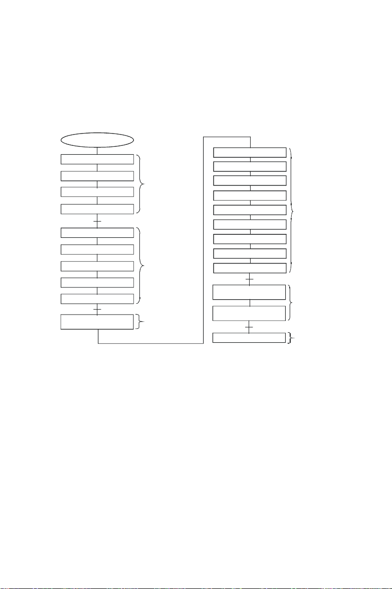
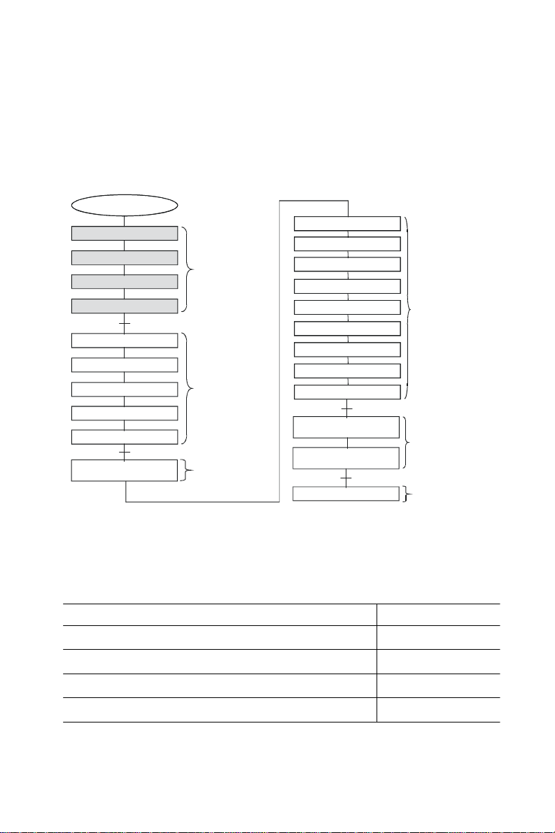
How to use this manual
The following flow chart demonstrates a thought process that you can
use when you plan your ADAM-5000/TCP system.
System Design Flow Chart
Select I/O Module
Select Power Supply
Select Link Terminal & Cable
Select Operator Interface
Determine Proper Environment
Install Main Unit a nd Module
System Mounting
Wiring and Connecting
I/O Address Mapping
Individual I/O Module
Introduction
Selecting Your
Hardware Component
Hardware Installation
Guide
I/O Modules
Introduction
System Hardware Configuration
Install Utility Software
I/O Module Configuration
I/O Module Calibration
Termina l Emul atio n
UDP Data Stream
Modbus Data Gateway
Using ADAM-5000/TCP
Using ADAM-5000/TCP
Network Setting
Security Setting
DLL Driver
Command Set
Appendix
System Configuration
Guide
Planning Your
Application Program
Relational Document &
Technical Information
Page 8

Contents
Chapter 1 Understanding Your System .................... 1-1
1-1 Introduction ................................................................. 1-2
1-2 Major Features ............................................................ 1-3
1-2-1 Communication Network ...............................................1-3
1-2-2 Modbus/TCP Protocol ....................................................1-3
1-2-3 Hardware Capacity & Diagnostic.................................1-3
1-2-4 Communicating Isolation...............................................1-4
1-2-5 Completed set of I/O modules for total s olutions ...........1-4
1-2-6 Built-in real-time OS and watchdog timer .......................1-4
1-2-7 Software Support ...........................................................1-4
1-2-8 Security Setting .............................................................1-5
1-2-9 UDP Data Stream .......................................................1-5
1-2-10 Modbus Ethernet Data Gateway ............. .............. .........1-5
1-3 Technical specification of ADAM-5000/TCP System .. 1-6
1-3-1 System ..........................................................................1-6
1-3-2 Ethernet Communication................................................1-6
1-3-3 Serial Communication .....................................................1-6
1-3-4 Power .............................................................................1-7
1-3-5 Isolation .........................................................................1-7
1-3-6 Mechanical.....................................................................1-7
1-3-7 Environment ................................................................... 1-7
1-3-8 Dimensions .................................................................... 1-7
1-3-9 Basic Function Block Diagram......................................1-8
1-4 LED Status of ADAM-5000/TCP main unit ............. 1-8
Chapter 2 Selecting Your Hardware Com ponents….2-1
2-1 Selecting I/O Module ................................................ 2-2
2-2 Selecting Power Supply ............................................ 2-6
2-3 Selecting Link Terminal and Cable .......................... 2-8
2-4 Selecting Operator Interface ................................... 2-10
Chapter 3 Hardware Installation Guide .................. 3-1
3-1 Determining the proper environment ...................... 3-2
3-1-1 Check the content of shipping box .................. ...............3-2
3-1-2 System Requirement ....................................................3-2
3-1-3 I/O modules ................................................................... 3-2
3-2 Installing your main unit and module .................... 3-3
Page 9

3-3 Mounting ......................................................................3-4
3-3-1 Panel mounting ...........................................................3-4
3-3-2 DIN rail mounting ........................................................3-4
3-4 Wiring and Connections ...........................................3-6
3-4-1 Power supply wiring ............................ .......................... 3-6
3-4-2 I/O modules wiring .....................................................3-7
3-4-3 System Network Connections ......................................3-8
3-5 Assigning address for I/O Modules ........................ 3-10
Chapter 4 I/O Module Introduction ........................ 4-1
Chapter 5 System Hardware Configuration ............ 5-1
5-1 System Hardware Configuration............................. 5-2
5-2 Install Utility Software on Host PC ........................ 5-3
5-3 ADAM-5000/TCP Windows Utility Overview......... 5-3
5-3-1 Main Menu .................................................................. 5-3
5-3-2 Ethernet Network Setting .............................................5-5
5-3-3 Add Remote Station ................................................... .... 5-8
5-3-4 I/O Module Canfiguration ...........................................5-9
5-3-5 Alarm Setting ............................................................... 5-14
5-3-6 I/O Module Calibration ................................................. 5-15
5-3-7 Firmware Update .......................................................... 5-17
5-3-8 Security Setting ...........................................................5-18
5-3-9 Terminal Emulation ............................................ ........... 5-19
5-3-10 Data Stream ................................................. ............... 5-20
5-3-11 Data Gateway Setting .............................................. ... 5-22
Chapter 6 Planning Your Application Program…... 6-1
6-1 Introduction .................................................................6-2
6-2 DLL (Dynamic Link Library) Driver ..........................6-2
6-2-1 Index ............................................................................. 6-2
6-2-2 Programming Flow ...................................................... 6-4
6-2-3 Function Descriptions .....................................................6-10
6-2-4 Return Codes .............. .......... ............ .............. ................ 6-30
6-3 ADAM-5000/TCP Command ..................................... 6-32
6-3-1 Command Structure ....................................................... 6-32
6-3-2 Modbus Function Code Introduction .............................. 6-33
6-4 Apply w i th ASCII Command for ADAM -5000/T C P
System ........................................................................... 6-39
6-4-1 Sytax of ASCII............................................................ 6-39
6-4-2 System Command Set............................................... 6-40
6-4-3 Analog Input Command Set ....................................... ... 6-48
6-4-4 Analog Output Command Set ...................................... 6-127
6-4-5 Digital Input/Output Command Set .............................. 6-141
Page 10

Appendix A Design Worksheets ............................A-1
Appendix B Data Formats and I/O Ranges............B-1
B.1 Analog Input Formats ...............................................B-2
B.2 Analog Input Ranges - ADAM-5017 ..............................B-4
B.3 Analog Input Ranges - ADAM-5018/5018P....................B-5
B.4 Analog Input Ranges - ADAM-5017H/5017UH...............B-7
B.5 Analog Output Formats ..............................................B-8
B.6 Analog Output Ranges..................................................B-8
B.7 ADAM-5013 RTD Input Format and Ranges...............B-9
Appendix C Grounding Reference........................C-1
C.1 Grounding ...................................................................C-3
C.2 Shielding ..................................................................... C-11
C.3 Noise Reduction Techniques......................................C-17
C.4 Check Point List ........................................................C-18
Page 11

Figures
Figure 1-1: Apply to System Application ................................................. 1-2
Figure 1-2: ADAM-500 0/T CP syste m & I/O modu le dimensions ………. 1-7
Figure 1-3: Function block diagram ......................................................... 1-8
Figure 1-4: ADAM-5000/TCP LED Indicators ........................................... 1-8
Figure 2-1: ADAM-5000 I/O Module Selection Cha r t .. ........... .................. 2-3
Figure 2-2: Ethernet Terminal and Cable Connection ............................ 2-8
Figure 2-3 RS-485 Terminal and Cable Connection ............................... 2-9
Figure 3-1: Module alignment and installation ........................................ 3-3
Figure 3-2: Secure the module to the system ......................................... 3-3
Figure 3-3: ADAM-50 00/ TC P pa nel mounting screw placement ........... 3-4
Figure 3-4: ADAM-5000/TCP DIN rail mounting ...................................... 3-5
Figure 3-5: Secure ADAM-5000/TCP System to a DIN rail ..................... 3-5
Figure 3-6: ADAM-5000/TCP power wiring .............................................. 3-6
Figure 3-7: ADAM-5000 I/O Module Terminal Block wiring .................... 3-7
Figure 3-8: System network connection ...................................... . ........... 3-8
Figure 3-9 Serial Network Connection ..................................................... 3-9
Figure 3-10: I/O Modules Address Mapping .... . .. ................................... 3-10
Figure 5-1: Hardware Configuration ........................................................ 5-2
Figure 5-2: operation Screen .................................................................... 5-3
Figure 5-4: Network Setting ...................................................................... 5-5
Figure 5-3: Tool Bar ................................................................................... 5-5
Figure 5-5: Communication testing function .......................................... 5-6
Figure 5-6: Define Device Name and Description ................................... 5-6
Figure 5-7: TCP/IP Network setting .......................................................... 5-7
Figure 5-8: Adding ADAM-5000/TCP screen ........................................... 5-8
Figure 5-9: Digital I/O Module Configuration ........................................... 5-9
Figure 5-11: Current Analog Input Status .............................................. 5-10
Figure 5-10: Operating and Indicating Icons ......................................... 5-10
Figure 5-12: setting range and integration time ................................... 5-11
Figure 5-13: Analog Module Configuration Screen .............................. 5-12
Figure 5-14: Counter/Frequency Module Configuration ...................... 5-12
Figure 5-15: Location of Counter/Frequency Module ........................... 5-13
Figure 5-16: Alarm Setting for Analog Input and Counter Modules .... 5-14
Figure 5-17: Zero Calibration .................................................................. 5-15
Figure 5-18: Span Calibration ................................................................. 5-15
Page 12

Figure 5-19: CJC Calibration .................................................................. 5-16
Figure 5-20: Analog Output Module Calibration ................................... 5-16
Figure 5-21: Firmware Upgrade .............................................................. 5-17
Figure 5-22: Password Setting ............................................................... 5-18
Figure 5-23: Command Emulation ......................................................... 5-19
Figure 5-24: Data Stream Configuration ................................................ 5-20
Figure 5-25: Data Stream Monitoring ..................................................... 5-21
Figure 5-26: RS-485 Modbus Network Setting ... ... .. .............................. 5-22
Figure 6-1: Request Comment Structure ............................................... 6-32
Figure 6-2: Response Comment Structure ............................................ 6-33
Figure 6-3: ASCII Command Structure in ADAM-5000/TCP ................. 6-39
Figure 6-4: Data format for 8-bit parameters ......................................... 6-64
Figure 6-5: The other bits are not used and are set to 0. ....................6-128
Figure C-1: Think the EARTH as GROUND. ............................................ C-3
Figure C-2: Grounding Bar ....................................................................... C-4
Figure C-3: Normal mode and Common modC ...................................... C-5
Figure C-4: Normal mode and Common modC ...................................... C-6
Figure C-5: The purpose of high voltage transmission ......................... C-7
Figure C-6: wire impedancC ..................................................................... C-8
Figure C-7: Single point grounding (1) .................................................... C-9
Figure C-8: Single point grounding (2) .................................................. C-10
Figure C-9: Single isolated cable ........................................................... C-11
Figure C-10: Double isolated cable ....................................................... C-12
Figure C-11: System Shielding .............................................................. C-13
Figure C-12: The characteristic of the cable ........................................ C-14
Figure C-13: System Shielding (1) ......................................................... C-15
Figure C-14:System Shielding (2) .......................................................... C-16
Figure C-15: Noise Reduction Techniques ........................................... C-17
Page 13

Tables
Table 2-1: I/O Selection Guidelines .......................................................... 2-2
Table 2-2: I/O Modules Selection Guide .................................................. 2-5
Table 2-3: Power Consumption of ADAM-5000 series ........................... 2-6
Table2-4: Pow er Supply Specification Table .......................................... 2-7
Table 2-5: Ethernet RJ-45 port Pin Assignment ..................................... 2-8
Table 4-1: I/O module support List……….. ............................................. 4-1
Table 6-1: Response Comment Structure ............................................. 6-33
Table 6-2: CPU Command Set Table ...................................................... 6-40
Table 6-3 Baud rate codes ...................................................................... 6-42
Table 6-4: ADAM-5013 RTD Input command Set Table ........................ 6-49
Table 6-5: ADAM- 501 7/ 50 18 Analog In p ut com man d S et T ab l e . .. .. .. . .. 6- 6 3
Table 6-6: ADAM-5017H Analog Input command Set Table ................ 6-80
Table 6-7 Analog Input alarm command set table ................................ 6-89
Table 6-8 Analog Input alarm command set table ...............................6-108
Table 6-9: Analog Output command Set Table ....................................6-127
Table 6-10: Counter/Frequency Command Set Table .........................6-149
Table A-1: I/O Data Base ........................................................................... A-3
Table A-2: Summary Required Modules ................................................. A-5
Table A-3: Table for Programming .......................................................... A-6
Page 14

Understanding Y
Chapter 1
our System
Using this Chapter
If you want to read about Go to page
Introduction 1-2
Major Feature 1-3
T echnical Specification 1-6
LED Status of ADAM-5000/TCP Ser ies main unit 1-8
Page 15

Chapter 1
Understanding Your System
1-1 Introduction Undoubtedly , Ethernet connectivity is becoming to a
big trend for industrial applications. Longer communication distances,
faster communication speeds, and greater advantages attract people into
developing their system based upon this network scenario. But there
used to be a thresh-old in connecting information layers and field control
layers. People usually had to prepare a data exchange server between
information systems and control systems as a communication bridge.
Obviously , it takes a lot of time and money. To meet user’s requirements,
Advantech announces the new DA&C system, the ADAM-5000/TCP
S er i es, the Ethernet I/O solution for people developing their eAutomation
architecture. It can be applied to various applications, such as traffic,
building, telecom, water treatment, and oth ers.
ADAM-5000/TCP Series include the following 2 products:
ADAM-5000/TCP: 8-slot Distributed DA&C System for Ethernet
ADAM-5000L/TCP: 4-slot Distributed DA&C System for Ethernet
1-2 ADAM-5000/TCP User’s Manual
Page 16

Understanding Your System
1-2 Major Features
1-2-1 Communication Network
By adopting a 32-bit RISC CPU, the ADAM-5000/TCP Series has
greatly ad- vanced data processing abilities for the user, especially for
network com- munications (response time < 5ms). There is a standard
RJ-45 modular jack Ethernet port on the ADAM-5000/TCP’S CPU
board, and I/O mod- ules field signals would be able to link with the
Ethernet directly without assistance from other hardware devices such as
converters or data gate- ways. The communication speeds can be autoswitched between 10 M and 100 Mbps data transfer rate depending
upon the network environ- ment. Through an Ethernet network, your
DA&C systems, computer workstations, and higher-level enterprise
MIS servers can access plant- floor data. Such data can be used in
system supervising, product sched- uling, statistical quality control, and
more.
1-2-2 Modbus/TCP Protocol Modbus/TCP is one of the most
popular standards for industrial Ethernet networks. Follow ing this
communication protocol, the ADAM-5000/TCP Series is easy to integrate
with any HMI software packages or user-developed applications that
support Modbus. Users do not have to prepare a specific driver for the
ADAM-5000/TCP Series when they install the DA&C sys- tem with
their own operating application. It will certainly reduce engineer effort.
Moreover, the ADAM-5000/TCP Se r i es works as a Modbus data server .
It allows eight PCs or tasks to access its current data simultaneously
from anywhere: LAN, Intranet, or Internet.
1-2-3 Ha rdware Capacity & Diagnostic Advantech’s
ADAM-5000/TCP Se r i e s is designed with a high I/O capacity and
supports all types of ADAM-5000 I/O modules. Providing eight slots for
any mixed modules, this DA&C system handles up to 128 I/O points
(four ADAM-5024s allowed). Different from other main units, the ADAM-
5000/TCP Se r ie s not only has a higher I/O capacity, but it also has a
smarter diagnostic ability. There are eight indicators on the front case of
the CPU module. Users can read the system status clearly, including
power, CPU, Ethernet link, Communication active, communication rate,
and more. In addition, there are also Tx and Rx LEDs on the Ethernet
port, indicating data transfer and reception.
ADAM-5000/TCP User’s Manual
Chapter 1
1-3
Page 17

Chapter 1
Understanding Your System
1-2-4 Communicating Isolation
High-speed transient suppressors isolate ADAM-5000/TCP Se r ies Ethernet
port from dangerous voltage up to 1500V
surge damage to whole system.
1-2-5 Completed set of I /O modules for
total solutions
The ADAM-5000/TCP Series uses a convenient backplane system
common to the ADAM-5000 series. Advantech’s complete line of
ADAM-5000 mod- ules inte grat es w ith the ADAM-5000/TCP Ser i es to
support your applications
(not include ADAM-5090). Full ranges of digital module supports 10 to
30 V
input and outputs. A set of analog modules provide 16-bit
DC
resolution and programmable input and output (including bipolar) signal
ranges. For details, refer to Chapter
4 I/O Modules.
1-2-6 Built-in real-time OS and watchdog timer The
microprocessor also includes a real-time OS and watchdog timer. The
real- time OS is a vaila ble to han dle seve ral task s at the sa me time . The
watchdog timer is designed to automatically reset the microprocessor if
the system fails. This feature greatly reduces the level of maintenance
required and makes the ADAM-5000/TCP Ser ies ideal for use in
applications which require a high level of system performance and
stability .
1-2-7 Software Support
Based on the Modbus standard, the ADAM-5000/TCP
Se ries firmware is a built-in Modbus/TCP server. Therefore,
Advantech provides the neces- sary DLL drivers, OCX component OPC
Server, and Windows Utility for users for client data for the ADAM5000/TCP Series. Users can configure this DA&C system via Windows
Utility; integrate with HMI software pack- age via Modbus/TCP driver
or Modbus/TCP OPC Server. Even more, you can use the DLL driver
or OCX component to develop your own applicati ons.
1-4 ADAM-5000/TCP User’s Manual
power spikes and avoid
DC
Page 18

Understanding Your System
Chapter 1
1-2-8 Security Setting
Though Ethernet technology comes with great benefits in
speed and integration, there also exist risks about network invasion
from outside. For this reason, a security protection design was built into
the ADAM-5000/TCP Series. Once the user has set the password into
the ADAM-5000/ TCP firmware, important system configurations
(Network, Firmware, Pass- word) can only be changed through password
verification.
1-2-9 UDP Data Stream Most of time, each host PC in a DA&C
system needs to regularly request the I/O devices via TCP/IP packs to
update current data. It may cause to data collision and lower
performance on the network, especially when there are frequent
communication between multi-servers and I/O devices. To reduce the
communication loading of the host computer on your Ethernet
network, the ADAM-5000/TCP Series also supports UDP
(User Datagram Protocol) protocol to broadcast the data packs to
specific IPs without requesting commands. Users can apply this
great feature to implement Data Stream, Event Trigger, and other
advanced functions.
1-2-10 Modbus Ethernet Data Gateway
Much more than an I/O system, ADAM-5000/TCP Series provides an
RS-485 network interface for other Modbus devices integration.
It work s as Ethernet Data Gateway, upgrading Modbus serial network
devices up to Ethernet layer. Maximum 16 nodes of ADAM-5511 or 3’rd
party products supported Modbus protocol are allowed to integrate
with an ADAM-5000/TCP Se ries. This great feature enlarges your system
scope, as opposed to other general dummy I/O system.
ADAM-5000/TCP User’s Manual
1-5
Page 19

Chapter 1
Understanding Your System
1-3 Technical specification of ADAM-
5000/TCP Series System
1-3-1 System
• CPU: ARM 32-bit RISC CPU
• Memory: 4 M B Flas h RAM
• Operating System: Real-time O/S
• Timer BIOS: Yes
• I/O Capacity: 8 slots (ADAM-5000/TCP)
4 slots (ADAM-5000L/TCP)
• Status Indicator: Power (3.3V , 5V), CPU, Communication (Link,
Collide, 10/100 Mbps, Tx, Rx)
• CPU Power Consumption: 5.0W
• Reset Push Bottom: Yes
1-3-2 Ethernet Communication
• Ethernet: 10 BASE-T IEEE 802.3
100 BASE-TX IEEE 802.3u
• Wiring: UTP , category 5 or greater
• Bus Connection: RJ45 modular jack
• Comm. Protocol: Modbus/TCP
• Data T ransfer Rate: Up to 100 Mbps
• Max Communication Distance: 100 meters
• Even Response Time: < 5 ms
• Data Stream Rate: 50 ms to 7 days
1-3-3 Serial Communication
• RS-485 signals: D ATA +, DATA-
• Mode: Half duplex, multi-drop
• Connector: Screw terminal
• T ransmission Speed: Up to 115.2 Kbps
• Max. Transmission Distance: 4000 feet (1220 m)
1-6 ADAM-5000/TCP User’s Manual
Page 20
1-3-4 Power
Understanding Your System
Chapter 1
• Unregulated 10 to 30V
DC
• Protection: Over-voltage and power reversal
1-3-5 Isolation
• Ethernet Communication: 1500 V
• I/O Module: 3000 V
1-3-6 Mechanical
DC
• Case: KJW with captive mounting hardware
• Plug-in Screw T erminal Block:
Accepts 0.5 mm 2 to 2.5 mm 2 , 1 - #12 or 2 - #14 to #22 AWG
1-3-7 Environment
• Operating T emperature: - 10 to 70º C (14 to 158º F)
• Storage Temperatur e: - 25 to 85º C (-13 to 185º F)
• Humidity: 5 to 95%, non-condensing
• Atmosphere: No corrosive gases
DC
NOTE: Equipment will operate below 30% humidity.
However, static electricity problems occur much more
frequently at lower hu- midity levels. Make sure you take
adequate precautions when you touch the equipment. Consider
using ground straps, anti- static floor coverings, etc. if you use
the equipment in low humidity environments.
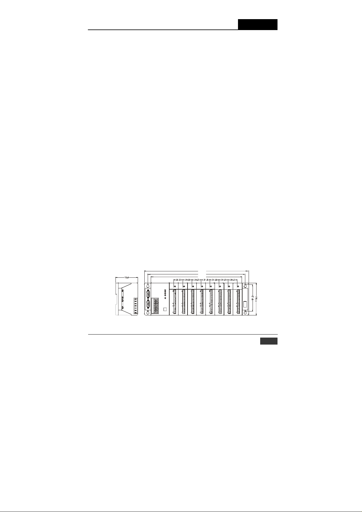
1-3-8 Dimensions The following diagrams show the dimensions
of the system unit and an I/O unit. All dimensions are in millimeters.
Figure 1-2: ADAM-5000/TCP system & I/O module dimensions
ADAM-5000/TCP User’s Manual
355.0
331.5
309.5
1-7
Page 21
Chapter 1
Understanding Your System
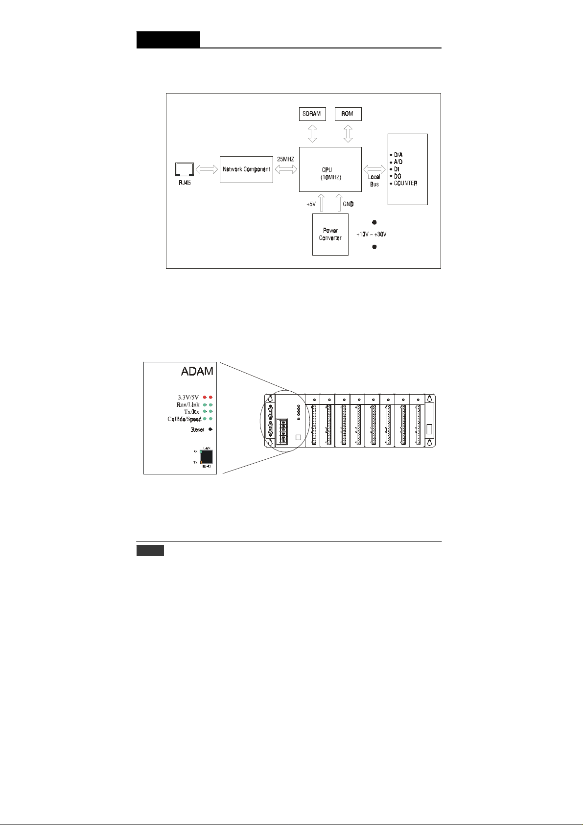
1-3-9 Basic Function Block Diagram
1-4 LED Status of ADAM-5000/TCP Se r i es main unit
There are eight LEDs on the ADAM-5000/TCP Se r i es front panel. The
LEDs indicate ADAM-5000/TCP’s system status, as explained below:
1-8 ADAM-5000/TCP User’s Manual
Figure 1-3: Function block diagram
Figure 1-4: ADAM-5000/TCP LED Indicators
Page 22

Understanding Your System
Chapter 1
(1) 3.3V: Red indicator. This LED is normal on when ARM CPU is
pow- ered on.
(2) 5V: Red indicator . This LED is normal on when ADAM-5000/TCP
Series system is powered on.
(3) Run: Green indicator. This LED is regularly blinks whenever the
ADAM-5000/TCP Series system is running.
(4) Link: Green Indicator . This LED is normal on whenever the ADAM-
5000/TCP’s Ethernet wiring is connected.
(5) Tx: Green indicator. This LED is designed for the spare function
(COM port transit indicator) in the future.
(6) Rx: Green indicator. This LED is designed for the spare function
(COM port receive indicator) in the future.
(7) Collide: Green indicator. This LED blinks whenever there is the
Ethernet data pack collision.
(8) Speed: Green indicator. This LED is on when the Ethernet
communi- cation speed is 100 Mbps.
(9) Rx (RJ-45): Green indicator. This LED blinks whenever the ADAM-
5000/TCP Series transmitting data to Ethernet.
(10) Tx (RJ-45): Y ellow indicator. This LED blinks whenever the ADAM-
5000/TCP Series receiving data from Ethernet.
ADAM-5000/TCP User’s Manual
1-9
Page 23

Page 24
Selecting Y
System Design Flow Chart
Select I/O Module
Select Power Supply
Select Link Terminal & Cable
Select Operator Interface
Determine Proper Environment
Install Main Unit a nd Module
System Mounting
Wiring and Connecting
I/O Address Mapping
Individual I/O Module
Introduction
our Har
Selecti ng Your
Hardware Component
Hardware Installation
Guide
I/O Modules
Introduction
dwar
System Hardware Configuration
Install Utility Software
I/O Mod ule Configuration
Network Setting
I/O Module Calibration
Security Setting
Ter min al Emu lation
UDP Data Stream
Modbus Data Gateway
Using ADAM-5000/TCP Series
Using ADAM-5000/TCP
e Components
DLL Driver
Series Command Set
Appendix
Chapter 2
System Configuration
Guide
Planning Your
Applic ation Program
Relational Document &
Technical Information
Using this Chapter
If you want to read about Go to page
Selecting I/O Module 2-2
Selecting Power Supply 2-6
Selecting Link Term inal & Cable (Ethernet) 2-8
Selecting Operator Interface 2-10
Page 25

Chapter 2
Selecting Your Hardware Components
2-1 Selecting I/O Module
To organize an ADAM-5000/TCP Series data acquisition & control
system, you need to select I/O modules to interface the main unit with
field de- vices or processes that you have previously determined. There
are sev- eral things should be considered when you select the I/O
modules. What type of I/O signal is applied in your system? How much
I/O is required to your system? How will you place the main unit for
concentrate the I/O poin ts of an entire process.
How many ADAM-5000/TCP Series main units are required for
distributed I/O points arrangement.
What is the required voltage range for each I/O module? What
isolation environment is required for each I/O module? What are
the noise and distance limitations for each I/O module? Refer to
table 2-1 I/O as module selection guidelines
Choose this type of For these
I/
O module:
Discr
and block I/O m
Discr
and block I/O m
ete input module Selector
ete output m
or operations (examples):
odule phot
br
swit
con
odul
e
Alarms, control relays, fans, l
odule
valves, motor starters,
types of field devices
switch
es, pu
oelectric eyes, limit s
eakers, proximity switches, level
ches, motor starter contacts, rela
t
acts, thumbwh
shbuttons,
witches, circuit OP
eel switches
soleno
Analog input module Thermoc
Analog out
put m
odule An
ouple signals, RTD
temperature transducers, pr
tr
ansducers,
humidity transducers, flow transd
potentiometers.
el
load cell tra
alog
valves, act
ectric motor dr
nsducers,
uators, char
ives, anal
Tab le 2-1: I/O Selectio n Guidelines
2-2 ADAM-5000/TCP User’s Manual
ights, horns,
ids
sign
als,
essur
e
ucers,
t r
og meters
Explanation:
I
nput mod
ules sense ON/OFF or
ENED/CLOSED sig
sign
als can be either ac or dc.
y
Out
put module signals interf
with O
N/OFF or OPENED
devices. Discrete signals can be
either ac or dc.
C
onvert continu
into i
nput
values for AD
50
00/TCP
Interpret ADAM-
ecorders,
output
to
analog
through transducers) for field
devices.
nals. D
iscrete
ace
/CL
OSE
ous analog signals
AM-
5000/TCP
Series
sign
als (ge
nerally
D
Page 26
Selecting Your Hardware Components Chapter 2
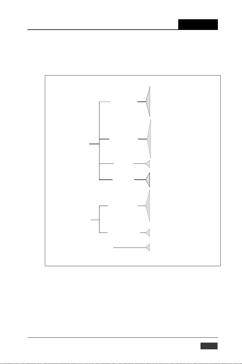
Advantech provides 15 types of ADAM-5000 I/O modules for various
applications so far. The figure 2-1 and tab le 2-2 will help you to slect th e
ADAM-5000 I/O modules quickly and easily.
Digital Input
Digital Mo dul e
Digital Output
Analog Module
Mixed I/ O
Analog Input
Analog Output
Counter
Communication Module
(for ADAM-5510 & ADAM-5511 only)
5051 Digital Input Module (16ch.)
5051D Digital Input Module With
LED (16 ch.)
5051S Isolated DI Module with L ED (16 ch.)
5052 Isolated DI Module (8ch.)
5056 Digital Output Module (16 ch.)
5056D Digital Output Module with LE D
(16 ch.)
5056S Isolated Digital Output Module
with LED (16 ch.)
5060 Relay Output Module (6 ch.)
5068 Relay Output Module (8 ch.)
5069 Power Relay Output Module (8 ch.)
5080 Counter/Frequency Module
(4 ch.)
5050 Digital I/O Module (16 ch.)
5055S I solated Di gital I/O Modu le
with LED (16 ch.)
5017 Analog Input Module (8ch.)
5017H Hi gh-speed Anal og Input Module
(8 ch.)
5017UH Ultra High-speed Analog I nput
Module (8 ch.)
5013 RTD Input Module (3ch.)
5018 T/C Input Module (7ch.)
502 4 An a l og Output Mo d ule (4ch.)
5090 Communication Module (8ch.)
Figure 2-1: ADAM-5000 I/O Module Selection Chart
ADAM-5000/TCP
User’s Manual 2-3
Page 27

Chapter 2
Selecting Your Hardware Components
Module ADAM-
Resolution 16 bit 16 bit 12 bit 12 bit 16 bit 16 bit -
Input
Channel
Sampling
Rate
Analog
Analog
Output
Digital
Digital
Output
Count-
er (32-
COM-
Module ADAM-5050 ADAM-5051 ADAM-5051D ADAM-5051S
Analog
Input
Analog
Output
Digital Input
and Digital
Output
Count-er
(32-bit)
COM-M
Isolation
Voltage
Input
Input
Input
Current
Input
Direct
Sensor Input
Resolution - - - - 12 bit
Voltage
Output
Current
Output
Digital
Input
Channels
and
Digital
Output
Channels
Channels - - - - -
Input
Frequency
bit)
Mode - - - - -
Channels - - - - -
M
Type - - - - -
Isolation
5013
Pt or Ni
RTD
3000
VDC
Resolution - - - Input Channel - - - Sampling Rate - - - Voltage Input - - - Current Input - - - Direct Sensor
Input
Resolution - - - Voltage
Output
Current Output - - - Digital Input
Channels
Digital Output
Channels
Channels - - - Input
Frequency
Mode - - - Channels - - - Type - - - -
2-4 ADAM-5000/TCP User’s Manual
ADAM-
5017
3 8 8 8 7 7 -
10 10 8K 200K 10 10 -
±150 mV
±500 mV
±1 V ±5
V ±10 V
- ±20 mA* ±20 mA*
- -
- -
- -
- -
- -
3000
VDC
16 DIO (bit-wise
selectabl-e)
ADAM-
5017H
±250 mV
±500 mV
±1 V ±5
V ±10 V
-
- - - -
- - - -
- - - -
- - - 2500 VDC
ADAM5017UH
V +10V
V ±10 V
4~20mA*
±20 mA*
3000
VDC
16 16 W/LED 16 W/LED
- - -
-
-
-
-
-
-
3000
VDC
ADAM-
5018
±15 mV
±50 mV
±100 mV
±500 mV
±1 V ±2.5
±20 mA* ±20 mA* -
J, K, T, E,
R, S, B
3000
VDC
ADAM-
5018P
±15 mV
±50 mV
±100 mV
±500 mV
±1 V ±2.5
V
J, K, T, E,
R, S, B
3000
VDC
ADAM-
V
- 0~10 V
0~20 mA
4~20 mA
- -
- -
- -
VDC
5024
3000
Table 2-2: I/O Modules Selection Guide
-
-
Page 28

Selecting Your Hardware Components
Chapter 2
Module ADAM-5052 ADAM-5055S ADAM-5056 ADAM-5056D
Resolution - - - - -
Analog
Input
Analog
Output
Digital
Input and
Digital
Output
Count-er
(32-bit)
COM-M
Isolation
Input
Channel
Sampling
Rate
Voltage Input - - - - Current
Input
Direct
Sensor
Input
Resolution - - - - Voltage
Output
Current
Output
Digital Input
Channels
Digital
Output
Channels
Channels - - - - Input
Frequency
Mode - - - - Channels - - - - Type - - - - -
- - - - -
- - - - -
- - - - -
- - - - -
- - - - -
- - - - -
8 8 W/LED - - -
- 8 W/LED 16 16 W/LED 16 W/LED
- - - - -
5000 VRMS 2500 VDC - - 2500 VDC
Module ADAM-5060
Analog Input
Analog Output
Digital Input
and Digital
Output
Count-er (32bit)
COM-M
Isolation
Resolution - - - Input
Channel
Sampling
Rate - - - Voltage Input - - - Current
Input
Direct
Sensor
Input
Resolution - - - Voltage Output - - - Current
Output
Digital Input
Channels
Digital Output
Channels
Channels - - 4 Input
Frequency - Mode - - Frequency,
Channels - - - 4
Type - - - RS-232
- - - -
- - - -
- - - -
- - - -
- - - -
6 relay
(2 form A/ 4 form C)
- - 1000 VRMS -
Table 2-2: I/O Modules Selection Guide
ADAM-5000/TCP User’s Manual
ADAM5068
8 relay
(8 form A)
ADAM-5080 ADAM-5090
- -
5000 Hz
(max) -
Up/Down
Counter,
Bi-direction
Counter
ADAM-
5056S /5056SO
-
2-5
Page 29

Chapter 2 Selecting Your Hardware Components
2-2 Selecting Power Supply
ADAM-5000/TCP Ser i e s system works under unregulated power
source be- tween +10 and +30 VDC. When you arrange different I/O
modules on ADAM-5000/TCP’s back plant, it may require comparable
power supply. Use the following steps as guidelines for selecting a
power supply for your ADAM-5000/TCP system.
• Refer to table 2.3 to check the power consumption of ADAM-5000/
Main Units Description Power Consumption
ADAM-5000/485 Distributed Data Acquisition and Control System based on RS-485 1.0 W
ADAM-5000E Distributed Data Acquisition and Control System based on RS-485 4.0 W
ADAM-5000/TCP Distributed Data Acquisition and Control System based on Ethernet 5.0 W
ADAM-5510 PC-Based Programmable Controller (With Battery Backup) 1.0 W
ADAM-5510M Enhanced PC-Based Programmable Controller (With Battery Backup) 1.2 W
ADAM-5511 PC-Based Programmable Controller with Modbus 1.0 W
ADAM-5510E 8-clot PC-Based Programmable Controller 1.2W
ADAM-5510/TCP Ethernet-enabled PC-Based Programmable Controller 2.0W
ADAM-5510E/TCP 8-clot Ethernet-enabled PC-Based Programmable Controller 2.0W
I/O Modules Description Power Consumption
ADAM-5013 3-Channel RTD Input Module 1.1 W
ADAM-5017 8-Channel Analog Input Module (mV, mA or High Voltage) 1.25 W
ADAM-5017H 8-Channel High speed Analog Input Module (mV, mA or High Voltage) 2.2 W
ADAM-5017UH 8-Channel Ultra High speed Analog Input Module (mV, mA or High Voltage) 2.2 W
ADAM-5018 7-Channel Thermocouple Input Module (mV, V, mA, Thermocopule) 0.63 W
ADAM-5024 4-Channel Analog Output Module (V, mA) 2.9 W
ADAM-5050 16-Channel Universal DIO 1.2 W
ADAM-5051 16-Channel Digital Input Module 0.53 W
ADAM-5051D 16-Channel Digital Input w/LED Module 0.84 W
ADAM-5056S 16-Channel Isolated Digital Input w/LED Module 0.8 W
ADAM-5056SO 16-Channel Digital Input w/LED Module 0.84 W
ADAM-5052 8-Channel Isolated DI 0.27W
ADAM-5055S 16-Channel Isolated DIO w/LED Module 0.68 W
ADAM-5056 16-Channel Digital Output Module 0.53 W
ADAM-5056D 16-Channel Digital Output w/LED Module 0.84 W
ADAM-5056S 16-Channel Isolated Digital Output w/LED Module 0.6 W
ADAM-5060 6-Channel Relay Output Module ( 2 of Form A, 4 of Form C) 1.8 W
ADAM-5068 8-Channel Relay Output Module ( 8 of Form A) 1.8 W
ADAM-5080 4-Channel Counter/ Frequency Input Module 1.5 W
ADAM-5090 4-Port RS232 Module 0.6 W
TCP Ser i es main unit and each I/O module.
Table 2-3: Power Co nsumption of ADAM-5000 series
ADAM-5000/TCP User’s Manual
2-6
Page 30

Selecting Your Hardware Components
Chapter 2
‚ Calculate the Summary of the whole system’s power consumption.
For example, there are following items in your system.
ADAM-5000/TCP * 3 & ADAM-5024 * 4 & ADAM-5017 * 6 &
ADAM-5068 * 5 & ADAM-5050 * 5 & ADAM-5080 * 4
ò
The power consumption is:
5W * 3 + 2.9W * 4 + 1 .25 * 6 + 1.8 W * 5 + 1.2W * 5 + 1. 5W * 4 = 55.1 W
ƒ Selet a suitable power supply from Table2.4 or other comparable power
resource for system operation
Specification
Input
I
nput Voltage
I
nput Frequency
I
nput Current
S
O
Out
Out
Overload Protection
General
Dimension
Oper
DI
hort Prot
ection
utput
put Voltage
put Current
ating Temperature
N-rail M
ountable
PWR-242
90
~264 V
AC
47
~63 Hz
1.2 A max.
Yes
+24
V
DC
2.1 A
Yes
181 mm x 113 mm x
60 mm (L x W x H)
0~
50º C (
32~122º F) 0~
Yes
PWR-
243
85
~132 V
AC
17
0~264
V
AC
47
~63 Hz
1.4 A max.
Yes
+24
V
DC
3 A
Yes
181 mm x 113 mm x
60 mm (L x W x H)
50º C (
32~122º F) 0~
No
PWR-
10
47
25 A/110 V
50 A/220 V
(Inrush current)
181 mm x 113 mm x
60 mm (L x W x H)
50º C (
Table2-4: Power Supply Specification Table
ADAM-5000/TCP User’s Manual
244
0~240
~63 Hz
Yes
+24
V
4.2 A
Yes
32~122º F)
No
DC
V
AC
AC
AC
2-7
Page 31

Chapter 2
Selecting Your Hardware Components
2-3 Selecting Link Terminal and Cable
Ethernet Network
Use the RJ-45 connector to connect the Ethernet port of the ADAM5000/TCP Se r i e s to the Hub. The cable for connection should be Category 3
(for10Mbps data rate) or Category 5 (for 100Mbps data rate) UTP/STP
cable, which is compliant with EIA/TIA 586 specifica tions. Maximum
length between the Hub and any ADAM-5000/TCP Series is up to 100
meters (approx. 300ft)
Figure 2-2: Ethernet Terminal and Cable Connection
Pin
number
1
2
3
4
5
6
7
8
Table 2-5: Ethernet RJ-45 port Pin Assignment
Signal
RD+
RD-
TD+
(Not Used)
(Not Used)
TD(Not Used)
(Not Used)
2-8 ADAM-5000/TCP User’s Manual
F
unction
Receive (+)
Receive
(-)
Transmit (+)
-
-
Transmit
(-)
-
-
Page 32

Selecting Your Hardware Components
Chapter 2
Serial Network
The system uses screw terminal for RS-485 twisted pair con nectio n as a
data gateway between Ethernet Sever and serial Modbus devices. See
Figure 2-3. The following information must be considered.
1. Twisted-pair wire compliant with EIA-422 or EIA-485 standards, which
contains 24 A WG thin copper conductor with copper mesh and aluminum foil for shielding.
2. Always use a continuous length of wire, do not combine wires to
attain needed length.
3. Use the shortest possible wire length.
4. Use the wire trays for routing where possible.
5. Avoi d running wires near high energy wiring.
6. To reduce electrical noise, it should be twisted as tightly as possible.
ADAM-5000/TCP User’s Manual
Figure 2-3 RS-485 Terminal and Cable Connection
2-9
Page 33

Chapter 2
Selecting Your Hardware Components
2-4 Selecting Operator Interface
To complete your data acquisition and control system,
selecting the operator interface is necessary. Adopting by
Modbus /TCP Protoco l, ADAM-5000/TCP Series exhibits high ability
in syst em inte grati on for va rious applications.
If you want to configure your ADAM-5000/TCP Ser i e s system, or
monitor cur- rent status, Advantech offers free charge software:
þ ADAM -5000/TCP Ser ie s Windows Utility
If you want to integrate ADAM-5000/TCP Series with HMI (Human
Machine Interface) software in a SCADA (Supervisory Control and Data
Acquisi- tion) system. There are a lot of HMI software packages, which
support Modbus/TCP driver.
þ Advantech Studio
þ Wonderware InTouch
þ Intell ution Fix of i-Fix
þ Any other software support Modbus/TCP protocol Moreover,
Advantech also provides OPC Server, the most easy-to-use data
exchange tool in worldwide. Any HMI software designed with OPC
Client would be able to access ADAM-5000/TCP Se rie s system.
þ Modbus/TCP OPC Server If you want to develop your own
application, the DLL driver and OCX component will be the best tools
to build up user’s operator interface.
þ AD AM-5000/TCP Ser ies DLL driver
þ ADAM-5000/TCP S er ie s OCX component
With these ready-to-go application software packages, tasks
such as remote data acquisition, process control, historical
trending and data analysis require only a few keystrokes.
2-10 ADAM-5000/TCP User’s Manual
Page 34

Chapter 3
Hardware Installation Guide
System Design Flow Chart
Select I/O Module
Select Power Supply
Select Link Terminal & Cable
Select Operator Interface
Determine Proper E nvironment
Install Main Unit and Module
System Mounting
Wiring and Connec ting
I/O Address Mapping
Individual I/O Module
Introduction
Using this Chapter
If you want to read about Go to page
Determining the proper environment 3-2
Installing your main unit and module 3-3
System Mounting 3-4
Wiring and Connection 3-6
System Network Connection 3-8
Assigning address for I/O modules 3-10
Selecting Your
Hardware Component
Hardware Installation
Guide
I/O Modules
Introduction
System Hardware Configuration
Install Utility Software
I/O Module Configuration
Network Setting
I/O Module Calibration
Security Setting
Ter min al Emu lation
UDP Data Stream
Modbus Data Gateway
Using ADAM-5000/TCP Series
Using ADAM-5000/TCP
Series Command Set
DLL Driver
Appendix
System Configuration
Guide
Planning Your
Application Prog ram
Relational Document &
Technical Information
Page 35

Chapter 3
Hardware Installation Guide
3-1 Determining the proper environment Before you start to
install the ADAM-5000/TCP Se r i e s system, there are some- thing needed
to check.
3-1-1 Check the content of shipping box
Unpack the shipping boxes and make sure that the contents include:
•
ADAM-50 00/TCP Se r i e s main unit with two blank slot covers
•
ADAM -4000/5000 Products Utility CD
3-1-2 System Requirement
•
Host computer
- IBM PC compatible co mputer with 486 CPU (Pentium is
recom- mended)
- Microsoft 95/98/2000/NT 4.0 (SP3 or SP4) or higher versions
- At least 32 MB RAM
- 20 MB of hard disk space available
- VGA color monitor
- 2x or higher speed CD-ROM
- Mouse or other pointing devices
- 10 or 100 Mbps Ethernet Card
•
10 or 100 Mbps Ethernet Hub (at least 2 ports)
•
Two Ethernet Cable with RJ-45 connector
•
Power supply for ADAM-5000/TCP Se ri e s (+10 to +30 V unregulated)
3-1-3 I/O modules At least one I/O module is needed to use
the system. Prepare the re- quired I/O modules as the interface for a
variety of field singles.
3-2 ADAM-5000/TCP User’s Manual
Page 36

Hardware Installation Guide
Chapter 3
3-2 Installing your main unit and module When inserting
modules into the system, align the PC board of the mod- ule with the
grooves on the top and bottom of the system. Push the
module straight into the system until it is firmly seated in the back plane
connector (see figure 3-1). Once the module is inserted into the system,
push in the retaining clips located at the top and bottom of the module to
ADAM-5000/TCP User’s Manual
firmly secure the module to the system (see figure 3-2).
Figure 3-1: Module alignment and installation
Figure 3-2: Secure the module to the system
3-3
Page 37

Chapter 3
Hardware Installation Guide
3-3 Mounting
The ADAM-5000/TCP Series system can be installed on a panel or on a
DIN rail.
3-3-1 Panel mounting Mount the system on the panel
horizontally to provide proper ventila- tion. You cannot mount the
system vertically, upside down or on a flat horizontal surface. A
standard #7 tatting screw (4 mm diameter) should be used.
Figure 3-3: ADAM-5000/TCP panel mounting screw placement
3-3-2 DIN rail mounting
The system can also be secured to the cabin et by using moun ting rails
(see figure 3-4). If you mount the system on a rail, you
should also consider using end brackets at each end of the rail. The
end brackets help keep the system from sliding horizontally along the
rail. This mini- mizes the possibility of accidentally pu lling the wiring
loose. If you ex am- ine the bottom of the system, you will notice two small
retaining clips. To secure the system to a DIN rail, place the system on to
the rail and gently push up on th e retaining clips (see figure 3-5). The
clips lock the system on the rail. To remove the system, pull down on the
retaining clips, lift up on the base slightly, and pull it away from the rail.
3-4 ADAM-5000/TCP User’s Manual
Page 38

Figure 3-4: ADAM-5000/TCP DIN rail mounting
Hardware Installation Guide
Figure 3-5: Secure ADAM-5000/TCP System to a DIN rail
ADAM-5000/TCP User’s Manual
Chapter 3
3-5
Page 39

Chapter 3
Hardware Installation Guide
3-4 Wiring and Connections This section provides basic
information on wiring the power supply, I/O units, and network
connection.
3-4-1 Power supply wiring
Although the ADAM-5000/TCP Series systems are designed for a
standard industrial unregulated 24 V DC power supply, they accept
any power un it that supplies within the rang e of +10 to +30 VDC. The
power supply ripple must be limited to 200 mV peak-to-peak, and the
immediate ripple voltage should be maintained between +10 and +30
VDC. Screw termi- nals +Vs and GND are for power supply wiring.
Note: The wires used should be sized at least 2 mm.
Power Supply
+10~+30 V
DC
+
-
+Vs
GND
COM
DA TA+
Figure 3-6: ADAM-5000/TCP power wiring
3-6 ADAM-5000/TCP User’s Manual
DA TA-
Page 40

Hardware Installation Guide
Chapter 3
3-4-2 I/O modules wiring
The system uses a plug-in screw terminal block for the interface between
I/O modules and field devices. The following information must be considered when connecting electrical devices to I/O modules.
1. The terminal block accepts wires from 0.5 mm to 2.5 mm.
2. Always use a continuous length of wire. Do not combine wires
to make them longer.
3. Use the shortest possible wire length.
4 . Use wire trays for routing where possible.
5 . Avoid running wires near high-ener gy wiring.
6 . Avoid running input wiring in close proximity to output wiring where
possible.
7. Avoid creating sharp bends in the wires.
ADAM-5000/TCP User’s Manual
Figure 3-7: ADAM-5000 I/O Module Terminal Block wiring
3-7
Page 41

Chapter 3
Hardware Installation Guide
3-4-3 System Network Connections
Ethnet Network
The ADAM-5000/TCP Series has an Ethernet communication port
allowed you to program, configure, monitor, and integrate into the
SCADA system. The figure 3-8 is a guideline to complete the system
network connection.
Figure 3-8: System network connection
3-8 ADAM-5000/TCP User’s Manual
Page 42

Hardware Installation Guide
Chapter 3
Serial Network
Working as an Ethernet Data Gateway, the ADAM-5000/TCP Series
provides an RS-485 interface to integrate serial devices for various
applications. Adopting by Modbus standard protocol, it solves the
communication problem between different networks and different
devices. Mean while, users can extend their system scope by
integrating up to 32 nodes of ADAM-5511 or other Modbus products,
such as meters, card readers, loadcell, and so on.
ADAM-5000/TCP User’s Manual
RS-485 Network
ADAM-5511
address of ADAM-5000/TCP Seri es on the RS-485 network will be
always node 1. Any Modbus devices integrated in this network should
be addressed from node 2 to 33.
ADAM
ADAM 5000/TCP
Ethernet I/O
+Vs
GND
COM
DATA+
DATA -
Ethernet
Modbus
Meter
3’rd party
Modbus Device
Up to 32 nodes
Figure 3-9 Serial Network Connection Note: The
3-9
Page 43

Chapter 3
Hardware Installation Guide
3-5 Assigning address for I/O Modules
Basing on Modbus standard, the addresses of the I/O
modules you place into the ADAM-5000/TCP Series system are
defined by a simple rule. Please refer the figures 3-9 to map the I/O
address.
Figure 3-10: I/O Modules Address Mapping For example,
if there is a ADAM-5024 (4-channel AO Module) in slot 2, the address of
this module should be 40017~40020.
Note: ADAM-5080 is a special 4-channel counter module. The data
type is designed as “unsigned long”. When you
in s e r t a n ADAM-5080 in slot 0, the address should be 40001,
40003, 40005
and 40007.
3-10 ADAM-5000/TCP User’s Manual
Page 44

4
I/O modules
Page 45

This manual introduces the detail specifications functions and
application wiring of each ADAM-5000 I/O modules.To organize an
ADAM-5000 series and ADAM-5510 Series Controller, you need to select
I/O modules to interface the main unit with field devices or processes that
you have previously determined. Advantech provides 20 types of ADAM5000 I/O modules for various applications so far. Following table is the I/ O
modules support list we provided for user’s choice. More detailed
specification and user’s guides, please refer the user’s manual of
ADAM-5000 IO Module
. It had integrated and collected this information.
Module Name Specification Reference
Analog I/O
Digital I/O
Counter/FrequencyADAM-5080 4-ch. Counter/Frequency Isolated
Serial I/O ADAM-5090 4-port RS232 Non-isolated
ADAM-5013 3-ch. RTD input Isolated
ADAM-5017 8-ch. AI Isolated
ADAM-5017H 8-ch. High speed AI Isolated
ADAM-5017UH 8-ch. Ultra High speed AI Isolated
ADAM-5018 7-ch. Thermocouple input Isolated
ADAM-5024
ADAM-5050 7-ch. D I/O Non-isolated
ADAM-5051 16-ch. DI Non-isolated
ADAM-5051D 16-ch. DI W/ LED Non-isolated
ADAM-5052 8-ch. DI Isolated
ADAM-5056 16-ch. DO Non-isolated
ADAM-5056D
ADAM-5060 6-ch. Relay output Isolated Relay Output
ADAM-5068
4-ch. AO Isolated
16-ch. DO W/LED Non-isolated
8-ch. Relay output Isolated
ADAM-5000
Table 4-1 I/O Module Support List
4-
2
Page 46

Chapter 5
System Hardware Configuration
System Design Flow Chart
Select I/O Module
Select Power Supply
Select Link Terminal & Cable
Select Operator Interface
Determine Proper E nvironment
Install Main Unit and Module
System Mounting
Wiring and Connec ting
I/O Address Mapping
Individual I/O Module
Introduction
Using this Chapter
If you want to read about Go to page
System Hardware Configuration 5-2
Install Utility Software 5-3
I/O Module Configuration 5-9
Ethernet Network Setting 5-5
I/O Module Calibration 5-15
Security Setting 5-18
T echnical Emulation 5-19
UDP Data Stream 5-20
Modbus Data Gateway 5-22
Selecting Your
Hardware Component
Hardware Installation
Guide
I/O Modules
Introduction
System Hardware Configuration
Install Utility Software
I/O Module Configuration
Network Setting
I/O Module Calibration
Security Setting
Ter min al Emu l ation
UDP Data Stream
Modbus Data Gateway
Using ADAM-5000/TCP Series
Using ADAM-5000/TCP
DLL Driver
Series Command Set
Appendix
System Configuration
Guide
Planning Your
Application Prog ram
Relational Document &
Technical Information
Page 47

Chapter 5
This chapter explains how to use Windows Utility to configure the
ADAM-5000/TCP Series system for various applications. Users can
learn the hardware connection, software installation, communication
setting and every procedure for system configuration from these
sections.
System Hardware Configuration
5-1 System Hardware Configuration
As we mentioned in chapter 3-1, you will need following items to complete your system hardware configuration.
System Requirement
• Host computer
- IBM PC compatible computer with 486 CPU (Pentium is recommended)
- Microsoft 95/98/2000/NT 4.0 (SP3 or SP4) or higher versions
- At least 32 MB RAM
- 20 MB of hard disk space available
- VGA c olor m onit or
- 2x or higher speed CD-ROM
- Mouse or other pointing devices
- 10 or 100 Mbps Ethernet Card
• 10 or 100 Mbps Ethernet Hub (at least 2 ports)
• Two Ethernet Cable with RJ-45 connector
• Power supply for ADAM-5000/TCP Series (+10 to +30 V
unregulated) Make sure to prepare all of the items above, then connect
the power and network wiring as figure 5-1.
Figure 5-1: Hardware Configuration
5-2 ADAM-5000/TCP User’s Manual
Page 48

System Hardware Configuration
Chapter 5
5-2 Install Utility Software on Host PC
ADAM-5000/TCP Ser ies Systems come packaged with a Utility CD,
containing ADAM Product series Utilities as system configuration tool.
While you Insert th e CD into the CD drive (e.g. D:) of the host PC, the
Utility soft- ware setup menu will start up automatically.
Click the ADAM-5000/TCP S eri es icon to execute the setup program.
There will be a shortcut of the Utility executive program on Windows’
desktop after completing the installation.
5-3 ADAM-5000/TCP S er i e s Windows Utility Overview
The Windows Utility offers a graphical interface that helps you configure the ADAM-5000/TCP Seri es main unit and I/O modules. It is
also very convenient to test and monitor your DA&C System. The
following guide- lines will give you some brief instructions on how to
use this Utility.
• Main Menu
• Ethernet Network Setting
• Adding Remote Station
• I/O Module Configuration
• Alarm Setting
• I/O Module Calibration
• Firmware Update
• Security Setting
• Terminal emulation
• Data Stream
• RS-485 Modbus Network Setting
5-3-1 Main Menu
Double Click the icon of ADAM-5000/TCP S e r i e s Windows Utility
shortcut, the Operation screen will pop up as Figure 5-2.
Figure 5-2: operation Screen
ADAM-5000/TCP User’s Manual
5-3
Page 49

Chapter 5
System Hardware Configuration
The top of the operation screen consists of a function menu and a tool
bar for user’s commonly operating funct ions.
Function menu
ile contents “Exit” Function, using to exit this Utility program.
Item F
Item T ool
Add Remote 5000/TCP : Create a new ADAM-5000/TCP located in other
Search for 5000/TCP: Search all ADAM-5000/TCP units in the
Refresh 5000/TCP: Refresh the specific ADAM-5000/TCP unit to verify
Terminal: Call up the operation screen of Terminal emulation to do
Monitor Data Stream: Call up the monitoring screen of stream data from
contents functions as below:
Ethernet domination, both available to local
LAN and Internet application.
spe- cific Ethernet domination. ( the same with
host PC’s Ethernet domination)
the system status.
the request / response command execution.
specific ADAM-5000/TCP .
Item S
etup contents Timeout and Scan Rate setting functions. Please be
aware of the time setting for other Ethernet domination usually longer
than local network.
bout contents information about software version, released date,
Item A
and support modules.
5-4 ADAM-5000/TCP User’s Manual
Page 50

System Hardware Configuration
Chapter 5
T ool Bar
There are five push buttons in the tool bar.
Figure 5-3: Tool Bar
5-3-2 Ethernet Network Setting
As the moment you start up this Windows Utility , it will search all ADAM5000/TCP Series on the host PC’s domination Ethernet network
automatically. Then the tree-structure display area will appeal with the
searched units and the relative IP address.
Tree-structure
ADAM-5000/TCP User’s Manual
Display Area
Figure 5-4: Network Setting
Status
Display Area
5-5
Page 51

Chapter 5
System Hardware Configuration
See Figure 5-4, there are also Host PC’s information in the status display
area, include host name and IP address. Moreover, the Windows Utility
provides network connection test tool for user to verify
whether the communication is workable. Key-in the specific IP
address you want to connect and click the PING button, the testing result
will show as Figure
5-5.
Figure 5-5: Communication testing function Since
Utility software detects the ADAM-5000/TCP Ser ies, on the network,
user can begin to setup each ADAM-5000/TCP Series station
individually with following steps.
Step1: Choose any one station, all I/O modules plugged in the main unit
will be listed on the tree-structur e disp lay area. Mean while, the
“Device Name” and “Device Description” are
editable by operator’s needs.
Figure 5-6: Define Device Name and Description
5-6 ADAM-5000/TCP User’s Manual
Page 52

System Hardware Configuration
Chapter 5
Step2: Click the Network tip to configure the TCP/IP network setting
Figure 5-7: TCP/IP Network setting
MAC Address: This is also called Ethernet address and needs no
fur- ther configuration.
Link Speed: This function will show the current linking speed to be
either 10Mbps or 100Mbps. However, the utility will autodetect the current transmission speed on the network
segment and set the transmission speed for the device
accordingly without your further efforts.
Duplex Mode: The utility will detect the current transmiss ion mode
(half-duplex or full-duplex) on the network segment, and
set the transmission mode for the device accordingly
without your further efforts.
IP Address, Subnet Mask, Default Gateway: The IP address identifies
your ADAM-5000/TCP Ser i es device on the global network. Each
ADAM-5000/TCP has same default IP address 10.0.0.1. Therefore,
please do not initial many ADAM-5000/TCP Series at the same time to
avoid the Ethernet collision.
If you want to configure the ADAM-5000/TCP Series in the host PC’s
dominat- ing network, only the IP address and Subnet Mask will need to
set ( host PC and ADAM-5000/TCP Series must belong to same subnet
Mask). If you want to configure the ADAM-5000/TCP Series via
Internet or ot her net- work dom ination, you have to ask your network
administrator to obtain a specific IP and Gateway addresses then
configure each ADAM-5000/ TCP Series with the individual setting.
ADAM-5000/TCP User’s Manual
5-7
Page 53

Chapter 5
System Hardware Configuration
5-3-3 Add Remote Station
T o meet the remote monitoring and maintenance requirements, ADAM5000/TCP Serie s System does not only available to operate in local
LAN, but also allowed to access from internet or intranet. Thus users
would able to configure an ADAM-5000/TCP Series easily no matter
how far it is. Select item T
button, the adding station screen will pop up as Figure 5-8.
Then key-in the specific IP address and click the A
communication suc- cess, the added ADAM-5000/TCP Series unit
should appeal on the tree-struc- ture display area.
ool\Add 5000/TCP in function menu or click the
dd button. If the
Figure 5-8: Adding ADAM-5000/TCP screen
Note: There are several conditions need to be sure before adding a
remote ADAM-5000/TCP Series system in the windows Utility.
1 . Be sure the specific IP is existed and available.
2 . Be sure to complete the network linkage for both sides.
3. Be sure to adjust the best timing of timeout setting.
4. Even you are not sure whether the communication is
work- able or not, there is also a “PING” function for
testing the network connection.
5-8 ADAM-5000/TCP User’s Manual
Page 54

System Hardware Configuration
5-3-4 I/O Module Canfiguration
Digital Input Output Module
Selecting ADAM-5000 Digital Modules includes ADAM-5050/5051(D)/
5051S/5052/5055S/5056(D)/5056S/5060/5068/5069, user can read
following i n- formation from the Utility.
Chapter 5
Location: Standard Modbus address.Windows Utility shows
Type: Data T ype of t he I/O channel . The data ty pe of Digita l I/O
Value: The current status on each channel of I/O Module.
Description: Describes the channel numbers and I/O types of the spe-
In addition to monitor the current DI/DO status, the Windows
Utility offers a graphical operating interface as figure 5-10. You can
read the Digital input status through the change of the indicator icons.
Oppo- sitely, you can write the digital output status through clicking the
indica- tor icons.
ADAM-5000/TCP
Figure 5-9: Digital I/O Module Configuration
theModbus mapping address of each I/O channel.
(Please refer to chapter 3-5 Assigning address for I/O
Modules) And the addresses will be the indexes for
applying into the data- base of HMI or OPC Server.
modules is always “Bit”.
The value of digital I/O modules could be “0” (OFF) or
“1” (ON).
cific module.
User’s Manual
5-9
Page 55

Chapter 5
Note: 1 . The indicator icons are only available to click for digital
Analog Input Module
Selecting ADAM-5000 Analog Input Modules includes ADAM-5013/
5017(H)/5018s, users can read following information from the Utility.
System Hardware Configuration
Figure 5-10: Operating and Indicating Icons
output channel.
2. The hexadecimal code will be calculated automatically for any
status.
Figure 5-11: Current Analog Input Status
Location: Standard Modbus address. (Refer to chapter 3-5 Assigning
address for I/O module)
5-10 ADAM-5000/TCP User’s Manual
Page 56

System Hardware Configuration
Chapter 5
Type: Data type of the I/O channel. The data type of analog Input mod-
ules is always “word”.
Value: The current status on each channel of I/O modules. Windows
Utility provides both decimal and hexadecimal values used for
different applications.
Description: Describes the channel numbers, sensor types, and
mea- surement range of the specified module. Before acquiring the current
data of an analog input module, you have to select the input range and
integration time. Th en the inpu t data will be
scaled as the specified range with engineer unit.
Figure 5-12: setting range and integration time
Note: Windows Utility allows user to Enable / Disable the current sta-
tus display.
Analog Output Module
Selecting an ADAM-5024 Analog Output Module, users can certainly
read the information abou t location, type, value, and Descrip tion. Actually, ADAM-5024 is designed with four different outputs channel, so
there are four channel configuration screens for signal range and output
value setting in the Utility. Once the setting value sends out, the system
will read back the value immediately to guarantee a correct analog output
signal.
ADAM-5000/TCP User’s Manual
5-11
Page 57

Chapter 5
Note: Initial Setting function: Adjust a initial output value you
Counter/Frequency Module
Selecting an ADAM-5080 Counter/Frequency Module, users also can
read the information about location, type, value, and description from
four individual channel configuration screens.
System Hardware Configuration
Figure 5-13: Analog Module Configuration Screen
want to set to the specified channel and click the set as
initial button, the channel will
output the same value each time when system is initial.
Figure 5-14: Counter/Frequency Module Configuration
5-12 ADAM-5000/TCP User’s Manual
Page 58

System Hardware Configuration
Chapter 5
However, the ADAM-5080 is a special module. Each channel is composed of an unsigned long and four bits. For example, if there is a
ADAM-5080 plugged in Slot 6 of ADAM-5000/ TCP system, the
address locations should be:
Figure 5-15: Location of Counter/Frequency Module
Note: 1st bit: Default ON “1”, available to set ON/OFF to start/stop
counting.
2nd bit: Normal OFF “0”, only accept a pulse ON signal to clear
the counter.
3rd bit: Normal OFF “0”, only tuig ON “1” when counter over-
flow. Users can write "0" to clear the overflow flag.
4th bit: Non used.
ADAM-5000/TCP User’s Manual
5-13
Page 59

Chapter 5
5-3-5 Alarm Setting To satisfy the needs of various applications,
ADAM-5000/TCP Ser i e s system provides Alarm setting function for
Analog Input and Counter Module. Users can set High/Low limit value
to identify the alarm status and trig- ger a digital output as an event
handling function.
System Hardware Configuration
Figure 5-16: Alarm Setting for Analog Input and Counter Modules
There are three alarm types in Analog Input Modules:
Disable: ADAM-5000/TCP Series dose not executive alarm
diagnosing func- tion.
Momentary: When the Input value is over or under the High/Low limit,
the alarm signal will be sent only once.
Latch: When the input value is over or under the High/Low limit, the
alarm signal will be latched till clicking the “Clear Latch” button.
Note: The alarm types of ADAM-5080 include “Disable” and “Latch
only.
5-14 ADAM-5000/TCP User’s Manual
Page 60

System Hardware Configuration
Chapter 5
5-3-6 I/O Module Calibration Calibration is to adjust the
accuracy of ADAM module. There are several modes for module’s
calibration: Zero calibration, Span calibration, CJC calibration, and
Analog Output calibration. Only analog input and out- put modules can
be calibrated, includes ADAM-5013, 5017, 5017H, 5018 and 5024.
Zero Calibration
1 . Apply power to the module and let it warm up for 30 minutes.
2. Make sure the module is correctly installed and properly configured
for the input range you want to calibrate.
3 . Use a precision voltage source to apply a calibration voltage to the V+
and V- terminals of the ADAM-5013, 5017, 5017H, and 5018 modules.
4 . Click the Execute button.
Figure 5-17: Zero Calibration
Span Calibration Follow the same procedure of zero calibration and
click the Execute but- ton.
Figure 5-18: Span Calibration
ADAM-5000/TCP User’s Manual
5-15
Page 61

Chapter 5
CJC Calibration
1. Prepare an accurate voltage source.
2 . Run the zero calibration and span calibration function.
3. Use a temperature emulation device (such as Micro-10) to send a
temperature signal to the ADAM module and then compare this signal with the value from the ADAM module. If the value is different
from the signal, adjust the CJC value to improve it.
System Hardware Configuration
Figure 5-19: CJC Calibration
Note: CJC (co ld junction sensor) calibration only applies
to the ADAM-5018
Analog Output Calibration
• ADAM 5024: 4 mA and 20 mA
Figure 5-20: Analog Output Module Calibration
5-16 ADAM-5000/TCP User’s Manual
Page 62

System Hardware Configuration
Chapter 5
5-3-7 Firmware Update
ADAM-5000/TCP Series supports all ADAM-5000 series I/O modules
and nec- essary operating function so far. But Advantech always
provides better hardware and software functions to improve the perfect
DA&C systems. Therefore, users will need to upgrade the firmware of
ADAM-5000/TCP Series someti me. Select the Firmware Upgrade tab
and cli ck B
rowsing to find the specific firmware (*.bin) for upgrade.
Figure 5-21: Firmware Upgrade Click the upgrade
button, then the new firmware will be downloaded into the ADAM5000/TCP Series system.
ADAM-5000/TCP User’s Manual
5-17
Page 63

Chapter 5
System Hardware Configuration
5-3-8 Security Setting
Though the technology of Ethernet discovered with great benefits in
speed and integration, there also exist risk about network invading form
anywhere. For the reason, the security protection design has
built-in ADAM-5000/TCP Series system. Once user setting the
password into the ADAM-5000/TCP Series firmware, the important
system configurations (Net- work, Firmware, Password) are only
allowed to be changed by password verificati on.
Note: The default password of ADAM-5000/TCP Series is
“00000000”. Please make sure to keep the correct password
by yourself. If you lose it, please contact to Advantech’s
technical support center for help.
5-18 ADAM-5000/TCP User’s Manual
Figure 5-22: Password Setting
Page 64

System Hardware Configuration
Chapter 5
5-3-9 Terminal Emulation You can issue commands and
receive response by clicking the Terminal button on the tool bar.
There are two kinds of command format supported by this
emulating function. Users can choose ASCII or Hexadecimal mo de as
their communication base. If the ASCII mode has been selected, the
Windows Utility will translate the request and response string both
in Modbus and ASCII format. Please refer Chapter 6-2 to use Modbus
Command; and refer Chapter 6-4 to apply ASCII command.
For example, select ASCII mode and key-in the ASCII command “$01M”
(read module name), then click Send
23.
. The response will show as figure 5-
Figure 5-23: Command Emulation
ADAM-5000/TCP User’s Manual
5-19
Page 65

Chapter 5
5-3-10 Data Stream
Data Stream Configuration In addition to TCP/IP communication
protocol, ADAM-5000/TCP Series sup- ports UDP communication
protocol to regularly broadcast data to spe- cific host PCs. Click the tip
of Data stream, then configure the broadcasting interval and the specific
IPs which need to receive data from the specific ADAM-
5000/TCP Series. This UDP Data Stream function broadcasts up to 8
host PCs simultaneously, and the interval is user-defined from 50ms to 7
Days.
System Hardware Configuration
Figure 5-24: Data Stream Configuration
Data Stream Monitoring
After finishing the configuration of Data Stream, you can select the item
“Monitor Data Stream” in the function bar or click icon to call up operation display as Figure 5-25.
5-20 ADAM-5000/TCP User’s Manual
Page 66

System Hardware Configuration
Figure 5-25: Data Stream Monitoring
Select the IP address of the ADAM-5000/TCP Series you want to
read d ata, then click “Start” button. The Utility software will begin to
receive the stream data on this operation display.
Chapter 5
ADAM-5000/TCP User’s Manual
5-21
Page 67

Chapter 5
System Hardware Configuration
5-3-11 Data Gateway Setting
ADAM-5000/TCP Series is designed with an RS-485 Modbus
Interface. As a Data Gateway, It integrates serial Modbus devices into
Ethernet applica- tion easily.
Click the tip of “RS-485/Modbus” to configure the RS-485 network setting with following steps.
1. Define the parameter of the network, includes Parity, stop bit, Baud
Rate (300~115200bps),and Timeout.
2. Click the Apply button, the password verification dialog block
will pop up.
3 . Key in your specific password and click “OK”, The setting is done.
5-22 ADAM-5000/TCP User’s Manual
Figure 5-26: RS-485 Modbus Network Setting
Page 68

Planning Y
our Application Pr
System Design Flow Chart
Select I/O Module
Select Power Supply
Select Link Terminal & Cable
Select Operator Interface
Determine Proper Environment
Install Main Unit and Module
System Mounting
Wiring and Connecting
I/O Address Mapping
Individual I/O Module
Introductio n
Selecting Your
Hardware Component
Hardware Installation
Guide
I/O Modules
Introduction
System Hardware Configuration
Install Utility Software
I/O Module Configuration
Network Setting
I/O Module Calibration
Security Setting
Terminal Emu lation
UDP Data Stream
Modbus Data Gateway
Using ADAM-5000/TCP Series
DLL Driver
Using ADAM-5000/TCP
Series Command Set
Appendix
Using this Chapter
If you want to read about Go to page
DLL Driver 6-2
Programming Flow6-4
Programming Flow 6-32
Comman d St ruc tu re 6-33
Modbus Function Code Introduction 6-39
Apply with ASCII Command 6-40
- Syst e m Co mm an d Se t 6-48
- Analog Input Command Set 6-127
- Analog Output Command Set 6-140
Chapter 6
ogram
System Configuration
Guide
Planning Your
Appl i c a ti on Program
Relational Document &
Technical Information
Page 69

Chapter 6
Planning Y our Application Program
6-1 Introduction After completing the system configuration, you can
begin to plan the application program. This chapter introduces two
programming tools for users to execute system data acquisition and
control. The DLL drivers and command sets provide a friendly
interface between your applica- tions and ADAM-5000/TCP Ser ies
system.
6-2 DLL (Dynamic Link Library) Driver The Dynam ic Link
Library (DLL) enables you to quickly and easily write Windows
applications for ADAM-5000/TCP Series systems. The library supports Borland C, Delphi, Visual C++, and Visual Basic. Since
ADAM-5000/TCP systems communicate with a host computer through
Ethernet, no additional driver needs to be installed. The DLL includes all
necessary function calls to utilize the ADAM-5000/TCP Series systems
to their fullest extent. In the same path with “ADAM 5000TCP
Series”after completing S/W installa- tion, you’ll find the relational
example files for each kind of programming languages after setup the
Windows Utility program. You can customize the source code to create
your own tailor-made ADAM-5000/TCP Series setup program or
monitoring system.
6-2-1 Index
Function Libraries Pages
ADAM5KTCP_Open 6-9
ADAM5KTCP_Close 6-10
ADAM5KTCP_Connect 6-11
ADAM5KTCP_Disconnection 6-12
ADAM5KTCP_GetDLLVersion 6-13
ADAM5KTCP_ReadReg 6-14
ADAM5KTCP_WriteReg 6-15
6-2 ADAM-5000/TCP User’s Manual
Page 70

Planning Y our Application Program
Function Libraries Pages
ADAM5KTCP_ReadCoil 6-16
ADAM5KTCP_WriteCoil 6-17
ADAM5KTCP_SendReceive5KTCPCmd 6-18
ADAM5KTCP_Add5KTCPForStream 6-19
ADAM5KTCP_ReadStreamData 6-20
ADAM5KTCP_ReadAlarmInfo 6-21
ADAM5KTCP_StartStream 6-22
ADAM5KTCP_StopStream 6-23
ADAM5KTCP_SetStreamAlarmState 6-24
ADAM5KTCP_Debug 6-25
ADAM5KTCP_UDPOpen 6-26
ADAM5KTCP_UDPClose 6-27
ADAM5KTCP_SendReceiveUDPCmd 6-28
ADAM-5000/TCP User’s Manual
Chapter 6
6-3
Page 71

Chapter 6
Planning Y our Application Program
6-2-2 Programming Flow
* Send a command and receiving response by UDP
ADAM5KTCP_SendReceiveUDPCmd( )
6-4 ADAM-5000/TCP User’s Manual
ADAM5KTCP_Open( )
ADAM5KTCP_SendReceiveUDPCmd( )
ADAM5KTCP_UDPOpen( )
ADAM5KTCP_UDPClose( )
ADAM5KTCP_Close( )
Page 72

Planning Y our Application Program
ADAM-5000/TCP User’s Manual
* Send a command and receiving response by TCP
ADAM5KTCP_Open( )
ADAM5KTCP_Connect( )
ADAM5KTCP_SendReceive5KTCPCmd( )
ADAM5KTCP_Disconnect( )
ADAM5KTCP_Close( )
Chapter 6
6-5
Page 73

Chapter 6
Planning Y our Application Program
* To receive stream data com ing from ADAM-5000/TCP Series (s)
ADAM5KTCP_StartStream( &hEvent )
6-6 ADAM-5000/TCP User’s Manual
ADAM5KTCP_Open( )
ADAM5KTCP_Add5KTCPForStream( )
hEvent=CreateEvent( )
hEvent signaled ?
Y
ADAM5KTCP_ReadStreamData( )
quit ?
Y
ADAM5KTCP_StopStream( )
ADAM5KTCP_Close( )
(A Win32 API)
N
N
Page 74

Planning Y our Application Program
Chapter 6
* To receive alarm information from ADAM-5000/TCP(s)
ADAM5KTCP_Open( )
ADAM5KTCP_Add5KTCPForStream( )
hEvent=CreateEvent ( )
ADAM5KTCP_SetStreamAlarmState(ADAM5KTCP_ReceiveStreamWhenAlarm)
(A Win32 API)
ADAM5KTCP_StartStream( &hEvent )
hEvent signaled ?
Y
ADAM5KTCP_ReadStreamDatat( )
1
ADAM5KTCP_ReadAlarmInfo( )
Y
Alarm info buffer is empty?
Y
quit ?
N
N
N
ADAM5KTCP_StopStream( )
ADAM-5000/TCP User’s Manual
ADAM5KTCP_Close( )
6-7
Page 75

Chapter 6
Planning Y our Application Program
* To read coil values
ADAM5KTCP_Open( )
ADAM5KTCP_Connect( )
ADAM5KTCP_ReadCoil( )
ADAM5KTCP_Disconnect( )
ADAM5KTCP_Close( )
* To write value to coil
6-8 ADAM-5000/TCP User’s Manual
ADAM5KTCP_Open( )
ADAM5KTCP_Connect( )
ADAM5KTCP_WriteCoil( )
ADAM5KTCP_Disconnect( )
ADAM5KTCP_Close( )
Page 76

Planning Y our Application Program
* To read holding register value
ADAM5KTCP_Open( )
ADAM5KTCP_Connect( )
ADAM5KTCP_ReadReg( )
ADAM5KTCP_Disconnect( )
ADAM5KTCP_Close( )
* To write value to ho lding registe r
ADAM5KTCP_Open( )
ADAM5KTCP_Connect( )
ADAM5KTCP_WriteReg( )
ADAM5KTCP_Disconnect( )
ADAM5KTCP_Close( )
ADAM-5000/TCP User’s Manual
Chapter 6
6-9
Page 77

Chapter 6
Planning Y our Application Program
6-2-3 Function Descriptions
ADAM5KTCP_Open
Description: Initiate the “adam5ktcp.dll” for using.
Syntax: int ADAM5KTCP_Open(void);
Parameters: void
Return: Please refer to Chapter6-2-4 “Return Codes” for more
detail information
6-10 ADAM-5000/TCP User’s Manual
Page 78

Planning Y our Application Program
ADAM5KTCP_Close
Description: T erminates using the “adam5ktcp.dll”.
Syntax: void ADAM5KTCP_Close(void);
Parameters: void
Return: void
ADAM-5000/TCP User’s Manual
Chapter 6
6-11
Page 79

Chapter 6
Planning Y our Application Program
ADAM5KTCP_Connect
Description: Establish a Windows Sockets connection in a speci-
Syntax: int ADAM5KTCP_Connect(char szIP[ ], unsigned
Parameter:
szIP[in]: the IP Address of the ADAM-5000/TCP that to be
port[in]: the TCP/IP connection port used with Modbus/TCP ,
iConnectionTimeout[in]: the specified timeout interval for connecting
iSendTimeout[in]: the specified timeout interval for sending a
iReceiveTimeout[in]: the specified timeout interval for receiving response
Return: Please refer to Chapter 6-2-4 “Return Codes” for more
6-12 ADAM-5000/TCP User’s Manual
fied ADAM-5000/TCP system.
short port, int iConnectionTimeout, int iSendTimeout,
int iReceiveTimeout);
connected
502 default
to the ADAM-5000/TCP
command to the ADAM-5000/TCP
from the ADAM-5000/TCP
detail information
Page 80

Planning Y our Application Program
ADAM5KTCP_Disconnect
Chapter 6
Description: Disconnect the Windows Sockets connection of the
specified ADAM-5000/TCP
Syntax: void ADAM5KTCP_Disconnect(void);
Parameter: void
Return: Please refer to Chapter 6-2-4 “Return Codes” for more
ADAM-5000/TCP User’s Manual
detail information
6-13
Page 81

Chapter 6
Planning Y our Application Program
DAM5KTCP _Get DLLVersion
Description: Read the version of ADAM-5000/TCP DLL driver
Syntax: int ADAM5KTCP_GetDLLV ersion(void);
Parameter: void
Return: 0x150 means Version 1.50
6-14 ADAM-5000/TCP User’s Manual
Page 82

Planning Y our Application Program
ADAM5KTCP_ReadReg
Chapter 6
Description: Reads the holding register value at a specified range
Syntax: int ADAM5KTCP_ReadReg(char szIP[],
Parameter:
szIP[in]: the IP Address of the ADAM-5000/TCP that to be
wID[in]: the specific device ID for an Modbus/TCP device.
wStartAddress[in]: the starting address that to be read
wCount[in]: how many holdings register to be read
wData[out]: a unsigned 16 bits array that stored the read holding
Return: Please refer to Chapter 6-2-4 “Return Codes” for more
described in parameters.
WORD wID, WORD wStartAddress, WORD wCount,
WORD wData[]);
connected
The ADAM-5000/TCP is always assigned as 1
register
detail information
ADAM-5000/TCP User’s Manual
6-15
Page 83

Chapter 6
Planning Y our Application Program
ADAM5KTCP_WriteReg
Description: Write the holding register value at a specified range
Syntax: int ADAM5KTCP_WriteReg(char szIP[], WORD
Parameter:
szIP[in]: the IP Address of the ADAM-5000/TCP that to be
wID[in]: the specific device ID for an Modbus/TCP device.
wStartAddress[in]: the starting address that t o be written
wCount[in]: ho w many holdings register to be written
wData[out]: a unsigned 16 bits array that stored th e value write
Return: Please refer to Chapter 6-2-4 “Return Codes” for more
described in parameters.
wID, WORD wStartAddress, WORD
wCount, WORD wData[]);
connected
The ADAM-5000/TCP is always assigned as 1
to holding value
detail information
6-16 ADAM-5000/TCP User’s Manual
Page 84

Planning Y our Application Program
ADAM5KTCP_ReadCoil
Description: Read the coils value at a specified range described
in parameters.
Syntax: int ADAM5KTCP_ReadCoil(char szIP[],
WORD wID, WORD wStartAddress, WORD wCount,
BYTE byData[]);
Parameter:
szIP[in]: the IP Address of the ADAM-5000/TCP that to be
connected
wID[in]: the specific device ID for an Modbus/TCP device.
The ADAM-5000/TCP is always assigned as 1
wStartAddress[in]: the starting address that to be read
wCount[in]: how many coils to be read
byData[out]: a 8 bit array that stored the read coil
Return: Please refer to Chapter 6-2-4 “Return Codes” for more
detail information
Chapter 6
ADAM-5000/TCP User’s Manual
6-17
Page 85

Chapter 6
Planning Y our Application Program
ADAM5KTCP_WriteCoil
Description: Write the coils value at a specified range described
in parameters.
Syntax: int ADAM5KTCP_WriteCoil(char szIP[], WORD
wID, WORD wStartAddress, WORD wCount, BYTE
byData[]);
Parameter:
szIP[in]: the IP Address of the ADAM-5000/TCP that to be
connected
wID[in]: the specific device ID for an Modbus/TCP device.
The ADAM-5000/TCP is always assigned as 1
wStartAddress[in]: the starting address that to be written
wCount [i n] : how many coils to be written
byData[out]: an unsigned 8 bit array that stored values written to
coil
Return: Please refer to Chapter 6-2-4 “Return Codes” for more
detail information
6-18 ADAM-5000/TCP User’s Manual
Page 86

Planning Y our Application Program
ADAM5KTCP_SendReceive5KTCPCmd
Description: This function is designed for user’s convenience,
accepting the ASCII format string as a command.
Then transform it to meet the Modbus/TCP specification.
Syntax: int ADAM5KTCP_SendReceive5KTCPCmd(char
szIP[], char szSendToTCP[], char
szReceiveFromTCP[], char szModbusSend[], char
szModbusReceive[]);
Parameter:
szIP[in]: the IP Address of the ADAM-5000/TCP that to be
connected
szSendT oTC P[in]: the ASCII format string that send to a ADAM-
5000/ TCP
szReceiveFromTCP[out]: the ASCII format string that response from
a ADAM-5000/TCP
szModbusSend[out]: the Modbus/TCP format string that send
to a
ADAM-5000/TCP
szModbusReceive[out]: the Modbus/TCP format string that
response from a A DAM-5000/TCP
Return: Please refer to Chapter 6-2-4 “Return Codes” for more
detail information
Chapter 6
ADAM-5000/TCP User’s Manual
6-19
Page 87

Chapter 6
Planning Y our Application Program
ADAM5KTCP_Add5KTCPForStream
Description: Assign a specified ADAM-5000/TCP to send stream
Syntax: int
Parameters: szIP[in]: the IP Address of the ADAM-5000/TCP
Return: Please refer to Chapter 6-2-4 “Return Codes” for more
6-20 ADAM-5000/TCP User’s Manual
data to the PC
ADAM5KTCP_Add5KTCPForStream(char
szIP[]);
that assign to send stream data to th e PC
detail information
Page 88

Planning Y our Application Program
ADAM5KTCP_ReadStreamData
Description: Receive stream data that comes from the specif ic
ADAM-5000/TCP
Syntax: int ADAM5KTCP_ReadStreamData(char
szIP[], struct _StreamData *pStreamData);
Chapter 6
Parameters:
szIP[in]: to specify the IP Address for a user to receive the
stream data
*pStreamData[out]: the stream data stored in _StreamData st ructure
Please refer to Chapter 6-2-5 “Data Structure” for
Return: Please refer to Chapter6-2-4 “Return Codes” for more
ADAM-5000/TCP User’s Manual
more detail information about _StreamData structure.
detail information
6-21
Page 89

Chapter 6
Planning Y our Application Program
ADAM5KTCP _ReadAlarmInfo
Description: Receive alarm information that comes from the spe-
cific ADAM-5000/TCP
Syntax: int ADAM5KTCP_ReadAlarmInfo
(struct _AlarmInfo *pAlarmInfo);
Parameters:
*pAlarmInfo[out]: the alarm information stored in _AlarmInfo
structure Please refer to Chapter 6-2-5 “Data
Structure” for more detail information about
_AlarmInfo structure.
Return: Please refer to Chapter 6-2-4 “Return Codes” for more
detail information
6-22 ADAM-5000/TCP User’s Manual
Page 90

Planning Y our Application Program
ADAM5KTCP_StartStream
Chapter 6
Description: Instruct the PC to start receiv ing stream data from
the ADAM-5000/TCP
Syntax: int ADAM5KTCP_StartStream
(HANDLE *EventFromApp);
Parameters:
*EventFromApp: the event object that would pass
down to ADAM5KTCP.DLL This event object
would be signaled either a stream data send to PC o r
an alarm status change in ADAM5000/TCP .Please refer to ADAM5KTCP_SetStream
AlarmState for more detail information.
Return: Please refer to Chapter 6-2-4 “Return Codes” for more
detail information
ADAM-5000/TCP User’s Manual
6-23
Page 91

Chapter 6
Planning Y our Application Program
ADAM5KTCP_StopStream
Description: Instruct the PC to stop receiving stream data
Syntax: int ADAM5KTCP_StopStream( );
Parameters: void
Return: void
6-24 ADAM-5000/TCP User’s Manual
Page 92

Planning Y our Application Program
ADAM5KTCP_SetStream AlarmState
Description: Set the criterion to signal the event object
Syntax: int ADAM5KTCP_SetStreamAlarmState(WORD
Parameters: wStreamAlarmState[in]: When ass ign ed to
ADAM5KTCP_Receive StreamI ng or eA la r m : means the
ADAM5KTCP.DLL always signals
Stream WhenAlarm: means ADAM5KTCP.DLL only signals event
Return: Please refer to Chapter 6-2-4 “Return Codes” for more
wStreamAlarmState);
event object when any stream data comes from
an ADAM-5000/TCP. Then the application can
receive the stream data by calling
“ADAM5KTCP_ReadStreamData()” function.
When assigned to ADAM5KTCP_Receive
object when a alarm status is triggered. Then
the application can receive the alarm information about the ADAM-5000/TCP by
calling
“ADAM5KTCP_ReadAlarmInfo()” function.
detail information
Chapter 6
ADAM-5000/TCP User’s Manual
6-25
Page 93

Chapter 6
Planning Y our Application Program
ADAM5KTCP_Debug
Description: Trace the executive information about streaming data
mechanism in ADAM5KTCP .DLL
(It is convenient to troubleshooting of user’s appli-
cations.)
Syntax: int ADAM5KTCP_Debug(int *iMatchIndex,
int
*iReceiveCount, int *iThreadRun, int *iTotalStream,
char szFromIP[]);
Parameters:
*iMatchIndex[out]: indicating which ADAM-5000/TCP cause signaling
the event object
0 means the first ADAM-5000/TCP , 1 means second,
2 means third, and so on. The ordinal is implied when
calling “ADAM5KTCP_Add5KTCPForStream()”
function.
*iReceiveCount[out]: counts how many stream data have arrival
*iThreadRun[out]: indicating the working thread status in
ADAM5KTCP .DLL
*iTotalStream[out]: res e r v e d
szFromIP[out]: specify the IP Address of ADAM-5000/TCP which
sends the stream data.
Return: Please refer to Chapter 6-2-4 “Return Codes” for more
detail information
6-26 ADAM-5000/TCP User’s Manual
Page 94

Planning Y our Application Program
ADAM5KTCP_UDPOpen
Description: Opens a UDP socket and sets the timeout of send/
receive interval to prepare send a
Syntax: int ADAM5KTCP_UDPOpen(int iSendTimeout, int
Parameters:
iSendTimeout[in]: the specified timeout interval for sending a
iReceiveTimeout[in]: the spe cif ied ti meo ut inte rv al f or rec eiv ing a
Return: Please refer to Chapter 6-2-4 “Return Codes” for more
command to ADAM-5000/TCP by UDP.
iReceiveTimeout);
command string to the ADAM-5000/TCP by UDP.
re- sponse string from the ADAM-5000/TCP by
detail information.
Chapter 6
ADAM-5000/TCP User’s Manual
UDP.
6-27
Page 95

Chapter 6
Planning Y our Application Program
ADAM5KTCP_UDPClose
Description: Closes the UDP socket that has been
opened by
“ADAM5KTCP_UDPOpen()”.
Syntax: int ADAM5KTCP_UDPClose();
Parameters: Void
Return: Please refer to Chapter 6-2-4 “Return Codes” for more
detail information.
6-28 ADAM-5000/TCP User’s Manual
Page 96

Planning Y our Application Program
ADAM5KTCP_SendReceiveUDPCmd
Description: Sends a command to ADAM-5000/TCP and receives
the response by UDP
Syntax: int
ADAM5KTCP_SendReceiveUDPCmd(char
szIP[], char szSend[], char szReceive[]);
Parameters:
szIP[in]: the IP Address of the ADAM-5000/TCP that send/
receive the command/response
szSend[in]: the string in ASCII format that send to the ADAM-
5000/TCP
szReceive[out]: the string in ASCII format that response from the
ADAM-5000/TCP
Chapter 6
ADAM-5000/TCP User’s Manual
6-29
Page 97

Chapter 6
Planning Y our Application Program
6-2-4 Return Codes Using these function libraries, you can read
the error message and the against response from the returning codes.
ADAM5KTCP_NoError (0)
ADAM5KTCP_StartupFailure (-1)
ADAM5KTCP_SocketFailure (-2)
ADAM5KTCP_UdpSocketFailure (-3)
ADAM5KTCP_SetTimeoutFailure (-4)
ADAM5KTCP_SendFailure (-5)
ADAM5KTCP_ReceiveFailure (-6)
ADAM5KTCP_ExceedMaxFailure (-7)
ADAM5KTCP_CreateWsaEventFailure (-8)
ADAM5KTCP_ReadStreamDataFailure (-9)
ADAM5KTCP_InvalidIP (-10)
ADAM5KTCP_ThisIPNotConnected (-11)
6-30 ADAM-5000/TCP User’s Manual
ADAM5KTCP_AlarmInfoEmpty (-12)
Page 98

Planning Y our Application Program
6-2-5 Data Structure
struct _StreamData
{
WORD DIO[8]; // DI/DO data for Slot0, Slot1,...., Slot7
WORD Slot0[8]; // AI/AO data for slot0
WORD Slot1[8]; // AI/AO data for slot1
WORD Slot2[8]; // AI/AO data for slot2
WORD Slot3[8]; // AI/AO data for slot3
WORD Slot4[8]; // AI/AO data for slot4
WORD Slot5[8]; // AI/AO data for slot5
WORD Slot6[8]; // AI/AO data for slot6
WORD Slot7[8]; // AI/AO data for slot6
}; //StreamData,*pStreamData;
struct _Alarm Inf o
{
BYTE bySlot; // the Slot of 5000/TCP which cause the
alarm change
BYTE byChannel; // the Channel of 5000/TCP which cause
the alarm change
BYTE byAlarmT ype; // 0: Low Alarm, 1: High Alarm
BYTE byAlarmStat us; // 0: Alarm Off, 1: Alarm On
BYTE byIndexOf5KTCP; // indicate the index 5000/TCP which
cause the alarm change, zero-based
char szIP[20]; // the IP address which cause the alarm
change
char szDateTime[48]; // e.x 2001/09/23 10:12:34:567 (Year/Month/
Day Hour:Minute:Second:mSecond)
};
ADAM-5000/TCP User’s Manual
Chapter 6
6-31
Page 99

Chapter 6
Planning Y our Application Program
6-3 ADAM-5000/TCP Command
ADAM-5000/TCP system accepts a command/response form with the
host computer. When systems are not transmitting the y ar e
in listen mode. The host issues a command to a system with a
specified address and waits a certain amount of time for the
system to respond. If no response arrives, a time-out aborts the
sequence and returns control to the host. This chapter explains
the structure of the commands with Modbus/TCP protocol, and
guides to use these command sets to implement user’s programs.
6-3-1 Command Structure It is important to understand the
encapsulation of a Modbus request or response carried on the
Modbus/TCP network. A complete command is consisted of command
head and command body. The command head is prefixed by six bytes
and responded to pack Modbus format; the command body defines
target device and requested action. Following ex- ample will help you
to realize this structure quickly.
Example:
If you want to read the value of ADAM-5017 in ADAM-5000/TCP’s slot
0(2 channels; address: 40001~40002), the request command should be:
Figure 6-1: Request Comment Structure
6-32 ADAM-5000/TCP User’s Manual
Page 100

Planning Y our Application Program
And the response should be:
Chapter 6
Figure 6-2: Response Comment Structure
6-3-2 Modbus Function Code Introduction
T o full-fill the programming requirement, there is a series of function code
standard for user’s reference...
Code (Hex) Name
01
02
03
04
05
06
08
15
16
Read Coil
Read Input Status
Read Ho
Read Input Registers
Preset Single Register
Preset Multiple Regi
Status
lding
Reg
Force Single Coil
Loopback Dia
Force Multiple Coils
gnosis
isters
Usage
Read Discrete Output Bit
Read Discrete Input Bi
Read 16-bi
fl
oating point process
W
rite data to force coil ON/OFF
Write data in 16-b
Diagnostic testing o
Write multiple data to force co
sters Write mu
t register. Used to read integer or
it integer format
ltiple data in 16-bit integer format
Table 6-1: Response Comment Structure
t
data.
f the communication
il ON/OFF
Function Code 01
The function code 01 is used to read the discrete output’s ON/OFF status of ADAM-5000/TCP in a binary data format. Request message
format for function code 01:
Station
Address
Function
Code
ADAM-5000/TCP User’s Manual
Start
Address
Byte
High
Command Body
Start
Address
Byte
Low
Requested
Number of
High
Byte
Coil
Coil Low Byte
por
Requested
Number of
6-33
t
 Loading...