

Page 1

S E R I A L C O M M U N I C A T I O N I N T E R F A C E F O R I N D U S T R I A L A U T O M A T I O N
User's Manual
ADAM-4541
ADAM-4542
Single-mode Fiber Optic to RS-232/422/485
Fiber Optic to
RS-232/422/485
Converter
Converter
Introduction
Fiber optic transmission offers the benefits of
wide bandwidth, immunity to EMI/RFI interference,
and secure data transmission. The ADAM-4541/
ADAM-4542 can be used as an RS-232/422/485
point-to-point or point-to-multipoint connection for
transmitting and converting
their equivalents within a fiber optic environment.
Fiber optics are the perfect
where the transmission medium must be protected
from
electrical
conditions or
The ADAM-4541/4542 is
various machinery equipped with RS-232/422/
485 communication ports (such as computer
systems or manufacturing machines). Using
standard ST connectors, the module's fiber optic
ports can accommodate a wide range of fiber
optic cable sizes, including 62.5/125 (9/125) m.
F
eatures
* Compact size economizes space
* Direct plug-and-play
* Easily mounted on a DIN-rail, panel or
piggyback
* Transmission speeds of up to 115.2 kbps
* Optical fibers enable transmission of 2.5 km for
ADAM-4541 and 15 km for ADAM-4542.
*
Half/Full-duplex,
mode
* Avoids lightning strikes and EMI/RFI
interference
* Prevents damage from electrostatic discharge
* Stable and error-free data transmission
* Automatic internal RS-485 bus supervision
* No
RS-485
* Transient suppression and over-current
protection on RS-422/485 data
* Reserved space for termination resistors
* LED for power and data
* Power requirement: +10 ~ +30 V
exposure, lightning, atmospheric
chemical
bidirectional transmissi on
external flow
full/half-duplex signals
solution
for applications
corrosion.
specifically
control signals required for
flow
designed to
lines
indication
DC
Specifications
Fiber Optics
Wavelength
and
link
Transmission
Distance
Optic a l P o wer
Budget (attenuation)
Power Consumption
* Casing: ABS with captive mounting hardware
* Communication mode: Asynchronous
* Connector: Plug-in screw terminal
* Fiber port: ST
* Transmission mode:
bidirectional
* Transmission rate: Up to 115.2 kbps
* Operating temperature: -10 ~ 70° C
(14 ~ 158° F)
* Operating humidity: 5 ~ 95% (non-condensing)
* Accessories (included): Nylon DIN-rail
mounting adapter, SECC panel mounting
bracket
Note: Fiber optics are designed for industrial
applications.
50/125 m, 62.5/125 m, and 100/140 m
are commonly used for multi-mode;
9/125 m are commonly for single-mode.
Installation
Unpacking
The ADAM-4541/4542 package includes the
following:
• 1 ADAM-4541 or ADAM-4542 modul e
• 1 mounting bracket
• 1 User's Manual
• 1 3P to DB 9 cable
(Red:RX, white:TX,
ADAM-4541 ADAM-4542
multi-mode single-mode
820 nm 1310 nm
2.5 km 15 km
12.5 dB 9
1 W (typical);
1.5 W (max.)
Full/Half-duplex,
Black:GND)
dB
1.6 W (typical);
2.1W (max.)
ADAM and the ADAM
logo
are trademarks of Advantech.
Part No. 2000000330 1st Edition Printed in Taiwan May 1999
Page 2
Switch and jumper Settings
Switch Settings
The ADAM-454114542 converter has two DIP
switches which set the data format (number of
bits) and baud rate for the ADAM network.
Please remember to configure the
in the network via software commands. Your
program and the PC's
the settings of the converter and repeater
modules.
serial
I1O
modules
port should match
SW1
controls
Switch 1
9, 10, 11 or 12 bits. The factory default is 10
bits: one start bit, eight data bits, one stop bit
and no parity bit.
When using the converter in combination with
other ADAM modules, do not change the
setting of the converter, sinc e ADAM modules
have a fiXed data forma t of ten data bits. The
option of changing to 9, 11 or 12 bits is for use
with other modules (other than ADAM modules)
that have different data formats. Should you
change the ADAM module's data format, be
aware that you
data format settings on
the network.
the data format. Data can be
default
will also
have to change the
all
the other modules in
SW2
Switch 2 sets the baud rate. The options
range from 1200 bps to 115.2 kbps. The
factory default is 9600 bps. Be aware that
when you change the baud rate, you
have to change the baud rate for
connected modules accordingly.
also
all
the
Default settings
The ADAM-454114542 is not addressable by
the host computer. The baud rate and data
format are set using SW1 and SW2 in the
converter. The default settings are:
Default
Function Setting
Baud rate 9600 bps
Data format 10 bits
The
following
settings for the ADAM-454114542:
ADAM-4541/4542 data
Data Format 1 Z
9 bits
*10 bits
11 bits ○
12 bits
二
Off ● 二 On
○
ADAM-4541/4542
Baud Rate 1 Z 3 4 5 6 7 8 9
1200 bps
2400 bps ○
4800 bps ○ ○
*
9600 bps ○ ○ ○
19.2 kbps ○ ○ ○ ○
38.4 kbps ○ ○ ○ ○ ○
57.6 kbps ○ ○ ○ ○ ○ ○
115.2 kbps ○ ○ ○ ○ ○ ○ ○
RS-2321422 ○ ○ ○ ○ ○ ○ ○ ○
○
二
Off ● 二 On
settings
tables
illustrate
the switch
format settings (SW1)
○ ○
●
○
●
* 二
baud rate settings (SW2)
●
○ ○ ○ ○ ○ ○ ○ ○
●
○ ○ ○ ○ ○ ○ ○
●
○ ○ ○ ○ ○ ○
●
* 二
●
●
Default
○ ○ ○ ○ ○
●
○ ○ ○ ○
●
Default
○ ○ ○
●
○ ○
●
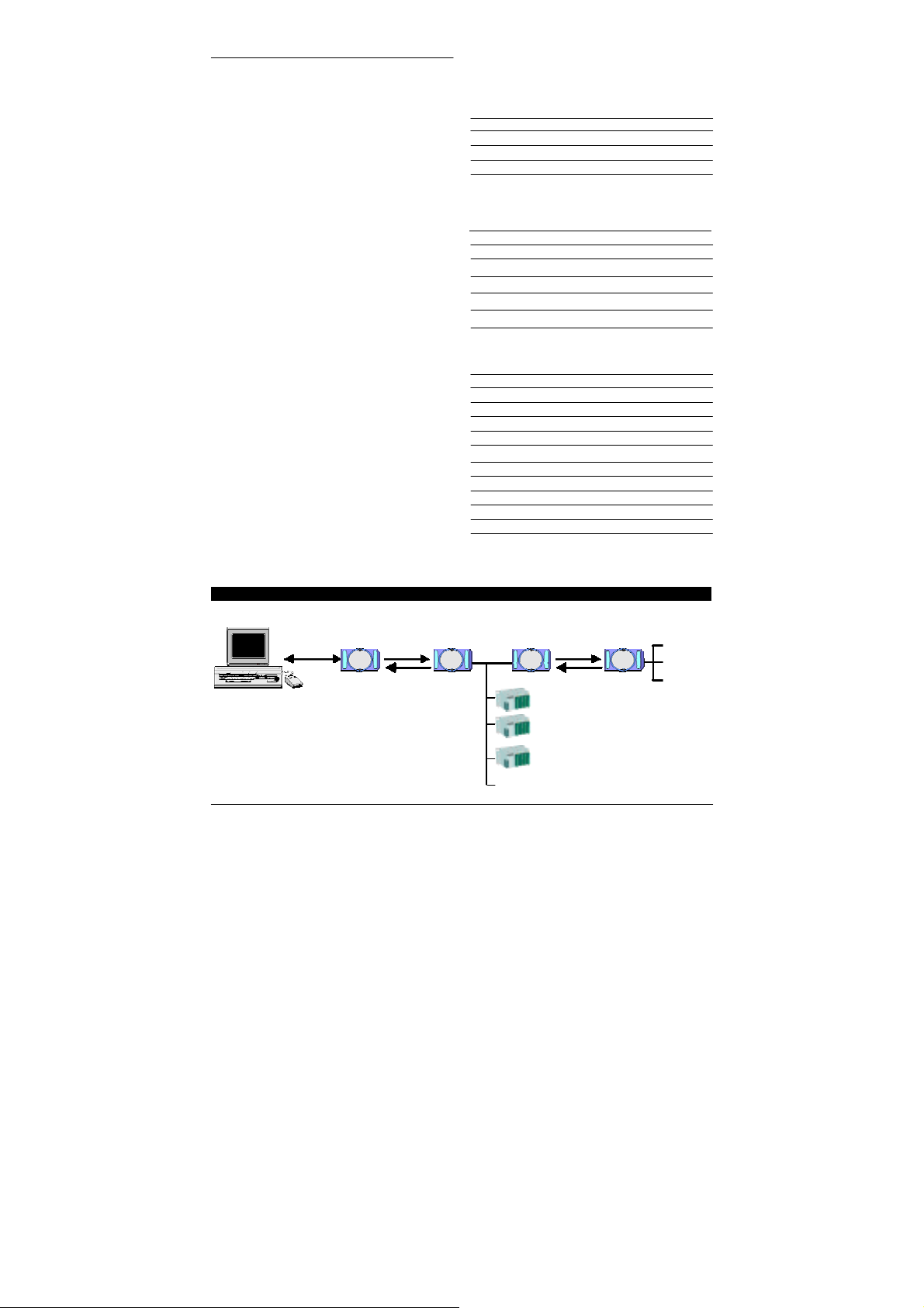
Block Diagram
RS-232
RS-422
RS-485
Fiber
ADAM
Optic
4541
(Fiber
ADAM
4541
Repeating)
ADAM-5000/485
Fiber
ADAM
Optic
4541
ADAM
4541
ADAM-454114542 User's Manual
○
●
Page 3

Example Program
The
following
COM1 and
Program:
#include <dos.h>
#include <io.h>
#include <stdio.h>
#include <conio.h>
#define TIME_OUT 4000
static int base0=0x3f8;
static int base1=0x2f8;
static char rec[160];
static char cmd[160];
void main ()
{
}
ADAM-454114542 User's Manual
program can be used as a diagnostic test for the ADAM-454114542. It
also
receive a string from COM1 of the computer (a loop-back test).
LOOPBACK.C
Signal Wiring
When you r un the
the ADAM-454114542 terminals as
PC
int i,timeout;
char rflag,tflag;
bioscom(0,0xE3,0); /* Set COM1 as follows: Baud Rate = 9600, Data Bits = 8, */
printf("\nInput string : "); /* Parity = none, Stop Bits = 1 */
gets(cmd);
while (cmd[0] != 'q' && cmd[0] != 'Q')
{
cmd[strlen(cmd)] = 0x0d;
i=0;
tflag=1;
while (tflag)
{ /* Send data */
outportb (base0,cmd[i]);
while ((inportb(base0+5) & 32) !=32);
rflag=1;
timeout=TIME_OUT;
while (rflag)
{ /* Check received data */
if ((inportb(base0+5) & 1) !=0)
{ /*Receive data */
rec[i]=inportb(base0);
if (rec[i] == 0x0d)
{
rec[i+1]='\0';
printf("\nReceived data : %s\n”,rec);
tflag=0;
}
rflag=0;
}
else
{ /* Check timeout */
timeout--;
if (timeout == 0)
{
printf("Timeout error");
rec[i+1]='\0';
rflag=0;
tflag=0;
}
}
}
i++;
}
printf("\nInput command : ");
gets(cmd);
}
eXample
RS-232/422
will
transmit a string to
program, connect
follows:
ADAM-4541
Rx
Tx
Page 4

Troubleshooting
Possible reasons for malfunction
汗
The TX and RX connection5 are re ver5ed.
Solution: Make 5ure the fiber connection i5 made
汗
Poor connection between the
and the communication port.
Solution: Make 5ure the ADAM-454114542 i5
汗
Attenuation on the fiber cau5e5 the
drop
Solution: Reduce the attenuation by reducing
汗
The connection between the communication port5
i5 neither DTE to DTE nor DCE to DCE
connection.
Solution: Add a converter to one of the
汗
The fiber ha5 been damaged.
Solution: Repair or rep1ace the fiber.
汗
The ADAM-454114542 ha5 been damaged.
Solution: U5e the 5upp1ied 5oftware to perform
5o that the TX of one end i5 connected
to the RX of the other.
5ecure1y p1ugged into the communication port.
be1ow
the accepted 1ev
1o55
connector
modem5, 5o that the pin a55ignment5
from the communication port to the
modem are from pin 2 to pin 3 and from
pin 3 to pin 2.
a 1oop-back te5t of the optica1
modem. Thi5
i5 damaged.
, tran5mi55ion di5tance5 , etc.
wi11
Power Supply
For the ea5e of u5e in indu5tria1 environment5,
the ADAM modu1e5 are de5igned to accept
indu5try 5tandard +24 V unregu1ated power.
Operation i5 guaranteed when u5ing any power
5upp1y between +10 and +30 V . Power ripp1e5
mu5t be 1imited to 5 V peak to peak, whi1e the
vo1tage in
+10 and +30 V .
are referenced at the modu1e connector.
The power cab1e5 5hou1d be 5e1ected according to
the number of modu1e5 connected and the 1ength
of the power
1ong
1imit 1ine
vo1tage drop5,
interference with communication wire5.
a11
ca5e5 mu5t be maintained between
1ine5.
cab1e5, we advi5e the u5e of thicker wire, to
vo1tage drop. In addition to 5eriou5
DC
A11
power 5upp1y 5pecification5
DC
When u5ing a network with
1ong
vo1tage
1ine5
ADAM-454114542
5igna1 1eve1 to
e1.
detect if the
DC
can
a15o
optica1
modu1e
cau5e
10
GND
+Vs
(R)
(B)
We advi5e that the
indicated on the
+V5 今 (R) Red
GND 今 (B)
modu1e5)
B1ack
-
+
fo11owing
5tandard co1or5 (a5
be u5ed for power
Power supply
-
+10 ~ +30 V
+
Front View
1ine5:
ADAM-454114542 U5er'5
Manua1
 Loading...