


-
S E R I A L C O M M U N I C A T I O N I N T E R F A C E F O R I N D U S T R I A L A U T O M A T I O N
ADAM-4521
Addressable RS-485 to RS-23 2 Converter with 1000 VDC
Isolation
Introduction
ADAM-4521 is an intelligent RS-485 to RS-232
converter specifically designed to connect RS-232
devices to an RS-485 network with other RS-485
devices. RS-232 is the most common transmission
standard. Although widely available on most computer
systems, measurement equipment, PLCs, and
industrial devices, its transmission speed, communication distance, and especially networking capability
are limited due to unbalanced transmission. The
ADAM-4521 addressable converter solves this
problem and lets you easily build up an RS-485
network with your RS-232 devices by assigning each
one an address for easier communication.
Built-in Intelligence
ADAM-4521 is equipped with a built-in microprocessor, which uses two UAR Ts and automatically
processes data before transmitting it to the RS-232
device. This makes ADAM-4521 able to allow different
baud rates between RS-232 devices and the RS-485
network. The microprocessor also verifies whether the
data is transmitted with the appropriate address,
which enables each device on the RS-485 network to
communicate with your PC over long distances.
RS-485 Network with Automatic Data
Flow Control
The RS-485 standard supports half-duplex
communication, meaning a single pair of wires is used
to both transmit and receive data. Handshaking
signals such as RTS (Request To Send) are normally
used to control the direction of the data flow, but a
special I/O circuit in the ADAM-4521 automatically
senses the direction of the data flow and switches the
transmission direction. No handshaking signals are
necessary.
Features
• Built-in microprocessor
• Transmission speeds of up to 115.2 kbps
• 1000 V
• Surge protection on RS-485 line
• RS-232 and RS-485 can be set to different baud
rates
• Automatic RS-485 data flow control
• Watchdog timer function included
• Power and data flow indicator for troubleshooting
• Reserved space for termination resistor
• Software configurable to either addressable or non
addressable mode
• Easily mounted on DIN rail, panel or piggyback
• All communication setups stored in EEPROM
isolation
DC
Specifications
• Transmission speed (bps): 300, 600, 1200, 2400,
4800, 9600, 19.2K, 38.4K, 57.6K, 115.2K (software
configurable)
Power requirement: Unregulated +10 to +30 V
•
with protection from power reversals
Case: ABS with captive mounting hardware
•
Accessories (included): Nylon DIN-rail mounting
•
adapter, SECC panel mounting bracket
RS-232 interface connector: Female DB-9
•
•
RS-422/RS-485 interface connector: plug-in
screw terminal (accepts AWG 1-#12 or 2-#14~#22
(0.5 to 2.5mm
Operating temperature: -10 to 70°C
•
Dimension: 2.36" x 4.41" (60mm x 120mm)
•
•
Power consumption: 1 W
2
) wires)
DC
ADAM and the ADAM logo are trademarks of Advantech.
Part No. 2003452100 3nd Edition Printed in Taiwan Aug. 2007
A
s
(G)
Installation
Power Supply
Initial
Inspection
We carefully inspect the ADAM-4521 both m echanic cally and electrically before w e ship it. It shou ld be
free of marks and scratches and in perfec t ord er on
receipt.
As you unpack the module, check it for si gns of
shipping damage (damaged box, scratc hes, de nts,
etc.). If it is damaged or fai ls to meet o ur spe cifica tions, notify our service departmen t o r you r local sale
representative immediately. Al so, ca ll the carr ier
immediately and retain the ship ping c arton a nd
packing material for inspectio n by t he carrie r. We will
then make arrangements to repair o r repl ace th e unit .
Before you begin installation, please make su re you
have the following items:
□
1 ADAM-4521 module
□
1 Bracket
□
1 Utility disk
Basic
Configuration
Before installing the ADAM-4521 in an existing
network, it should be configured. Though all modules
are initially configured at the factory, it is recommended that you check the baud rate settings.
Factory Default Settings:
Protocol: RS-485
Buad Rate: 9600 bps
Delimiter: {
Addressable
Mode:
Add cr: Yes
Address: 01
For the ease of use in industrial environments the
DAM modules are designed to accept industry
standard +24 V
guaranteed when using any power supply between
+10 and +30 V
peak to peak while the voltage in all cases must be
maintained between +10 and +30 V
supply specifications are referenced at module
connector.
The power cables should be selected according to the
number of modules connected and the length of the
power lines. When using a network with long cables,
we advise the use of thicker wire to limit the line
voltage drop. In addition to serious voltage drops,
long voltage lines can also cause interference with
communication wires.
We advise that the following standard colors (as
indicated on the modules) be used for power lines:
+Vs
(R) Red
GND (B) Black
Communication Wiring
We recommend that shielded-twisted- pair cable s that
comply with the EIA RS-485 standard be use d with
the ADAM network to reduce interfere nce. On ly one
set of twisted-pair cables is required to transmit both
Data and RTS signals. We advise that the f ollow ing
standard colors (as indicated on the modules ) be
used for the communication lines:
DATA +
DATA -
unregulated power. Operation is
DC
. Power ripples must be limited to 5V
DC
. All power
DC
(Y)
Yello w
Green
ADAM-4521 User's
Manual
Software Configuration
w
The ADAM-4521 comes with a utility disk containing
software with the following capabilities:
• Baud rate configuration
• Address configuration
• Addressable or non-addressable mode selection
• RS-485 or RS-422 mode
NOTE: Before configuring the ADAM-
The main screen consists of a menu bar at the top
and a status field which displays information about the
connected modules. When you first start the program,
it will automatically scan for any connected modules
and display their data. The status field lists module
characteristics and configuration parameters.
4521, make
host
RS-485
Figure 1 Main Screen
NOTE: An asterix sign “*” after the
sure
through an RS-422 or
line.
module's address indicates that
the module is in the INIT* state.
COMport
To configure your communication port, press
COMport icon. A menu will appear allowing you to
change which port you are using, the baud rate, and
the timeout.
Search
To scan the network for connected devices, click the
right button on the COM port to search the existed
com port. A window will appear and prompt you for
a value from 0 to 255. It will then scan all the
addresses from 0 to that number.
selection
it is connected to your
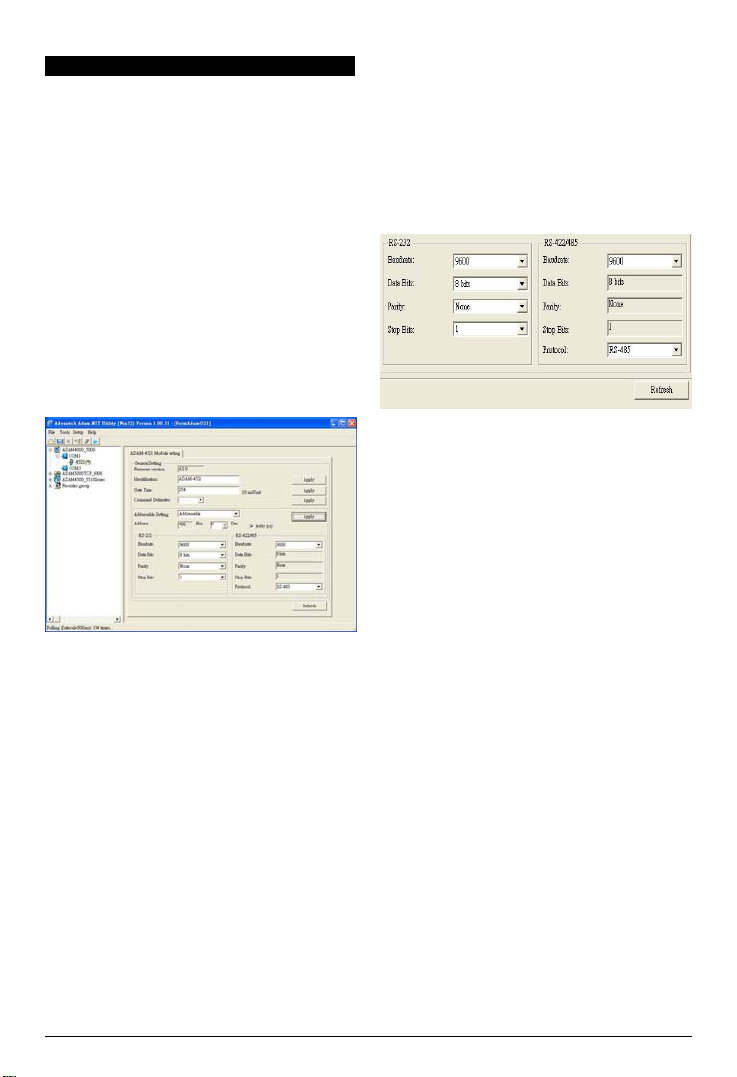
Setup
When you enter the setup screen, look at the
below frame of screen. You can see the RS-232
setting and the RS-485 setting. Please check the
setting of the interface. You can choose a proper
item to fit your owned setting. After you finish the
setting, please remember to press the Apply button
on the right side.
Figure 2 Setup Options
To change the basic settings, select the item the
1.
press <Enter>. Choose the parameter you wish to
change, and press <Enter>. A small popup windo
will appear with the configuration options for that
parameter. Choose the proper value, and press
<Enter>.
To change the RS-232/RS-485(RS-422) baud rate
2.
settings, select RS-232 Frame or RS-422/485
Frame and press <Enter>. Choose the parameter
you wish to change and press <Enter>. A window
will appear with the configuration options for that
parameter. Choose the proper value and press
<Enter>. In addition, you can assign the module
with proper ID via the Identification option.
The Mode (addressable or non-addressable) and
3.
Baud Rate options need special attention because
they can only be changed when ADAM-4521 is in
the INIT* state. To alter the Mode and Baud Rate,
do the following:
• Power all components on except ADAM-4521.
• Power ADAM-4521 on while shorting the INIT*
and GND terminals.
• Configure the Mode and/or Baud Rate.
• Power ADAM-4521 off.
• Remove the grounding of the INIT* terminal,
and power ADA M-4521 on.
• Check the settings.
INIT* state default settings:
Baud Rate:
Protocol:
Address:
9600
RS-485
00h
bps
ADAM-4521 User's
Manual

A
fter you have made the changes for a block of
[
]
A
4.
parameters, press <Apply>. You will be asked if
you are satisfied with the changes you have
made or not. Press “Yes” to keep the changes
you have made, “No” to escape without changing
the values.
NOTE: When changing configuration
parameters, always make sure a
window appears notifying you that
the target module has confirmed
the changes.
Terminal
This selection allows
commands
Advantech ASCII and Modbus Scree
Choosing
command test mode, where you send commands one at
a time by typing them into the top blank and
pressing <Send>. The response appears in the bottom
blank. To send the command again, simply press
<Send>.
Modbus
mode is a Modbus type of command test.
Previous commands and their responses stay on the
screen for you to refer to. If you want to repeatedly send
a command, press <Start>
and you can choose the Modbus type to fit your setting.
There are Coil Status, Input Status, Holding Register,
Input Register.
box on the right hand side of the screen shows the
communication parameters for the serial line such as
the baud rate and number of stop bits.
you to directly
on the RS-485 line. It
Advantech ASCII
send
has
n.
will place the ADAM-4521 in
Figure 3 Command Test
Quit
Choosing File on the menu bar, then choose the
Exit button to ends the ADAM utility program.
and receive
two
options:
Command Set
To avoid communication conflicts when several
devices try to send data at the same time, all actions
are instigated by the host computer. The basic form is
a command/response protocol with the host initiating
the sequence.
When modules are not transmitting, they are in listen
mode. The host issues a command to a module with a
specified address and waits a certain amount of time
for the module to respond. If no response arrives, a
timeout aborts the sequence and returns control to the
Syntax
[delimiter character]
checksum] [carriage return
Every command begins with a delimiter character. The
first four commands can use a dollar sign $ or a
percentage sign %, but the Data Pass command uses
one of eight special characters, as described on the
following page.
The delimiter character is followed by a two-character
address (hexadecimal) that specifies the target
module. The actual two character command follows
the address. Depending on the command, an optional
data segment follows the command string. An optional
two character checksum may be appended to the total
string. Every command is terminated by a carriage
return (cr).
NOTE:
Command
Syntax
$AA6(ID)
$AA7
$AAC(delimiter)
$AAD
Delimiter
AA(data)
[address]
[command] [data]
ALL COMMANDS SHOULD BE
ISSUED IN UPPERCASE
CHARACTERS.
Command Name
Set ID
Read ID
Set Delimiter
Read Delimiter
Data Pass
ADAM-4521 User's
Description
Assign an ID of
up
to 24
bytes to
the
module at
address
Read the ID from
Data Pass
bytes of data to
AA.
the
module at
address
AA.
Set the delimiter
character
for the
command.
Read the
delimiter
from
character
the
module at
address
AA.
Tell the module at
address AA to
pass
up to 32
the RS-232
device.
Manual

Command
)
Set ID
Description
Syntax
Response
Example
Read ID
Description Read the ID from the module at
Syntax
Response
Example
Descriptions
Assign
an ID of up to 24
module at
$AA6(identification) (cr)
!AA (cr) if the command
command: $246ADAM NETWORK 1 (cr
response:
!24 (cr)
The command
address
24h to write "ADAM NETWORK
1" to EEPROM.
AA.
$AA7 (cr)
!AA(identification) (cr)
command: $247 (cr)
response:
!24ADAM NETWORK 1 (cr)
The command
address
24h to return the identification
data from EEPROM.
address
asks
asks
bytes
AA.
is
valid.
the module at
the module at
to the
address
Data Pass
Description Tell the module at
Syntax
Response
Example
to 32
bytes
of data to the
(delimiter)AA(data) (cr)
depends
on the device
command: {24#02 (cr)
response:
The command
address
232 communication port.
24h to
asks
send
address
AA to
RS-232
the module at
#02 (cr) to the
pass
up
device.
RS-
Set Delimiter
Description set the delimiter character for the Data
Syntax
Response
Example
Read Delimiter
Description Read the delimiter character from the
Syntax
Response
Example
P
ass
command. There are 8
characters
to
choose
asks
address
AA.
command.
asks
from:
is
the module at
the module at
: [ ] ^ { | } ~
$AAC(delimiter) (cr)
!AA (cr) if the command
command: $24C{ (cr)
response:
!24 (cr)
The command
address
24h to write delimiter character
{ to EEPROM.
module at
$AAD (cr)
!AA(delimiter) (cr) if the command
valid. (delimiter) is a character for the
Data
Pass
command: $24D (cr)
response:
!24{ (cr)
The command
address
24h to return the delimiter
character from EEPROM.
ADAM-4521 User's
Manual
special
valid
is

Example Program
D
This demo program demonstrates how you might send a string of data to your HP34401A Multimeter (RS-232
device) via the ADAM-4521
.
ADAM-4521 Configuration Status:
ADDRESS:02
MODE:ADDRESSABLE
DELIMITER: {
ADD(CR):NO
RS-485 baud(9600),N,8,1
RS-232 baud(9600),N,8,2
HP34401A RS-232 baud(9600),N,8,2
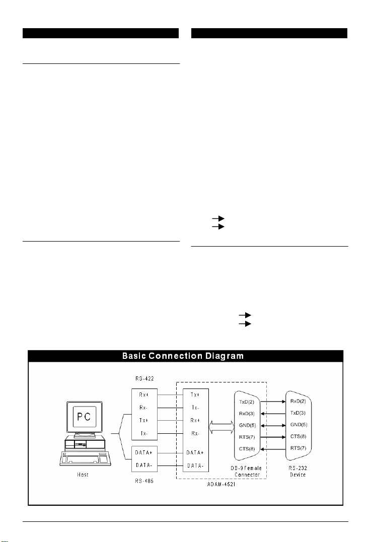
PC
(RS-485)
(RS-485)
DATA-
DATA-
DATA+
8
AM-4521
A
DATA+
7
/* set data=8 stop=1 no parity */
/* disable COM1 interrupt */
.
COM1
Program: DEMO01.C
#include <dos.h>
#include <io.h>
#include <stdio.h>
#include <conio.h>
#define TIME_OUT 500000
static
int base0=0x3F8;
static
char rec[36];
static
char cmd[40];
void
send(void);
void
receive(void);
void main()
{
outp(base0+3,0x80); /* set DLAB=1 */
outp(base0 ,0x0C); outp(base0+1,0x00); /* set buad=9600 */
outp(base0+3,0x03);
outp(base0+1,0x00);
printf("\nInput string : ");
gets(cmd);
while (cmd[0] != 'q' && cmd[0] != 'Q')
{
send();
receive();
printf("\nInput string : ");
gets(cmd);
}
}
(RS-232)
2 TX
3 RX
5 GND
(RS-232)
2 RX
3 TX
5 GND
HP-34401A
ADAM-4521 User's
Manual

void send()
{
static int i,flag;
i=strlen(cmd);
cmd[i]=0x0a; /* HP-34401A uses LF(0x0a) as the end of an incoming command. */
cmd[i+1]=0x0d;
i=0;
flag=1;
while (flag)
{
outportb(base0,cmd[i]); /* Send data */
while((inportb(base0+5)& 0x40)!=0x40);
if(cmd[i] == 0x0d)
flag=0;
i++;
}
while( (inportb(base0+5)&0x40) !=0x40);
}
void receive(void)
{
int i,flag;
long int timeout;
i=0;
flag=1;
timeout=TIME_OUT;
while (flag)
{ /* Check receiver data */
if ((inportb(base0+5) & 1) !=0)
{
rec[i]=inportb(base0); /* Receive data */
if(rec[i] == 0x0a)/* HP34401A uses 0x0a as the end of an outgoing command. */
rec[i+1]='\0';
flag=0;
printf("\nReceived data : %s",rec);
}
i++;
}
else
{ /* Check timeout */
timeout--;
if (timeout == 0)
{
flag = 0;
printf("\nTimeout error\n");
}
}
}
}
Output
Input string:
Timeout error
Input string:
Received data:
Input string:
Received data:
Input string:
Received data:
ADAM-4521 User's
Manual
{02:SYST:REM (Put the multimeter into remote operation mode.)
{02*IDN? (Read the multimeter ID.)
HEWLETT-PACKARD,34401A,0,3-1-1
{02:SYST:VERS? (Ask what version of SCPI the multimeter conforms to.)
1991.0
{02:READ?
+6.91849000E-04
(Trigger the readings, and read the results.)

ADAM-4521 Dimensions
FRONT VIEW REAR VIEW
SIDE VIEW PANEL MOUNTING
BRACKET
TOP VIEW DIN-RAIL MOUNTING
ADAPTER
ADAM-4521 User's
Manual
 Loading...