

Page 1

900 Series
Industrial Ethernet
Switch
Installation
& User’s Guide
Page 2
2
Industrial Eth e rne t Swit c h Inst a ll ati on Gu ide
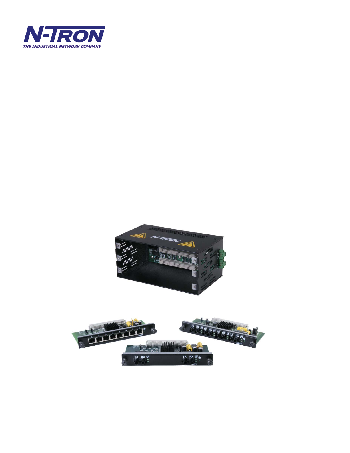
900B/900N (3 Slot Enclosure and Backplane)
900B-FP
908TX
902FX-SC
(Filler Panel for empty slots)
(Module)
(Module)
902FX-ST (Module)
902FXE-SC-YY
902FXE-ST-YY
(Module)
(Module)
904FX-SC (Module)
904FX-ST
904FXE-SC-YY
(Module)
(Module)
904FXE-ST-YY (Module)
Where: YY = -15, -40, or -80
(Revised 8/3/2009)
Page 3
3
Copyright, © N-TRON Corp., 2008
N-TRON Corp.
820 S. University Blvd., Suite 4E
Mobile, AL 36609
All rights reserved. Reproduction, adaptation, or translation without prior written permission from N-TRON
Corp. is prohibited, except as allowed under copyright laws.
Ethernet is a regist ered trademark of Xerox Corporation. All other product names, company names, logos
or other designations mentioned herein are trademarks of their respective owners.
The information contained in this document is subject to change without notice. N-TRON Corp. makes no
warranty of any kind with regard to this material, including, but not limited to, the implied warranties of
merchantability or fitness for a particular purpose. In no event shall N-TRON Corp. be liable for any
incidental, special, indirect or consequential damages whatsoever included but not limited to lost profits
arising out of errors or omissions in this manual or the information contained herein.
Warning
Do not perform any services on the unit unless qualified to do so.
Do not substitute unauthorized parts or make unauthorized modifications to the unit.
Do not operate the unit with the top cover removed, as this could create a shock or fire hazard.
Do not block the air vents on the sides or the top of the unit.
Do not operate the equipment in the presence of flammable gasses or fumes. Operating electrical equipment
in such an environment constitutes a definite safety hazard.
(Revised 8/3/2009)
Page 4

4
Safety Warnings
ELECTRICAL SAFETY
WARNING: Disconnect the power cable before removing the enclosure top.
WARNING: Do not operate the unit with the top cover removed.
WARNING: Do not work on equipment or cables during periods of lightning activity.
WARNING: Do not perform any services on the unit unless qualified to do so.
WARNING: Do not block the air vents.
WARNING: Observe proper DC Voltage polarity when installing power input cables. Reversing
voltage polarity can cause permanent damage to the unit and void the warranty.
LASER SAFETY (904FXE and 902FXE Only)
(Revised 8/3/2009)
CAUTION: CLASS 1 LASER PRODUCT. Do not stare into the laser!
Page 5

5
900 Series Hazardous Location Installation Requirements
1. WARNING: EXPLOSION HAZARD. DO NOT DISCONNECT UNIT WHILE CIRCUIT IS LIVE,
UNLESS KNOWN TO BE NON-HAZARDOUS.
2. AVERTISEMENT: RISQUE D’EXPLOSION. NEPAS DE’BRANCHER TANT QUE LE CIRCUIT
EST SOUS TENSION, A’MOINS QU’IL S’ A GISSE D’UN EMPLACEMENT NON DANGEREUX.
3. WARNING: Install only in accordance with Local & National Codes of Authorities Having Jurisdiction.
4. Power must be supplied by an isolating source, and a 3.3A max rated UL recognized fuse must be
installed immediately before the unit.
5. Class I, Div 2 installations require that all devices connected to this product must be UL listed for the area in
which it is installed.
6. Only UL listed wiring with temperature ratings greater than 90OC permitted for Class I, Div 2 installations
operating at temperatures up to 70OC ambient.
7. Limited Operating Voltage: 12-30V for Class I, Div 2 installations.
(Revised 8/3/2009)
Page 6

6
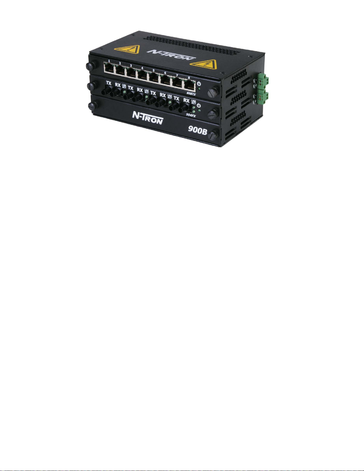
900 Series Industrial Ethernet Switches
The 900 Series Modular Industrial Ethernet Switches support high speed layer 2 switching between ports.
The 900B and 900N enclosures contain a three slot backplane that supports up to three modules. The
908TX, 902FX and 904FX modules are the available modules. The N-TRON Corp. 900B is housed in a
ruggedized steel enclosure, and can withstand industrial temperatures, as well as extreme shock & vibration.
The 908TX is an 8 port module that is capable of auto negotiating 10/100 Mb and half/full duplex
communications. The N-TRON 908TX also supports MDIX auto sensing (for auto connector of straight
through or crossover cables) and provides 8 Category 5 compliant 10/100-BaseT connections for high
performance network design, and hub/repeater upgrades.
The 902FX is a two port 100Mb module that supports multimode fiber. ST and SC connectors are
available.
The 902FXE is a single mode (laser) version of the 902FX, and can support distances of up to 80km.
The 904FX and 904FXE are four port versions of the 902FX and 902FXE respectively.
Key Features
• Full IEEE 802.3 & 100BASE-FX Compliance
• Extended Environmental Specifications
• Support for Full/Half Duplex Operation
• LED Link/Activity Status Indication
• Auto Sensing Speed and Flow Control
• Auto MDIX (908TX only)
• Up to 4.8 Gb/s Maximum Throughput
• Industry Standard DIN-Rail Enclosure
(Revised 8/3/2009)
Page 7

7
PACKAGE CONTENTS
Please make sure the Ethernet Switch package contains the following items:
1. 900 Series Ethernet Switch
2. Installed Modules
3. This Installation Guide
Contact your carrier if any items are dama ged.
INSTALLATION
Read the following warning before beginning the installation:
WARNING
The 902FXE and 904FXE unit contain a class 1 laser. Do not stare into the laser beam (fiber optic
connector) when installing or operating the product.
Never install or work on electrical equipment or cabling during periods of lightning activity.
Disconnect the power cable before removing the enclosure top.
Do not operate the unit with the top cover removed
UNPACKING
Remove all the equipment from the packaging, and store the packaging in a safe place.
File any damage claims with the carrier.
(Revised 8/3/2009)
Page 8

8
902FX/FXE & 904FX /FXE HALF DUPLEX SETUP
All 900 series fiber modules are factory configured for full duplex operation. The setting is controlled
by jumper JP1 on the backplane.
Note: Most 100Mbit fiber systems will be compatible with this Full Duplex setting. If Half Duplex
operation is desired, then follow these steps using proper wrist strap grounding techniques:
1. Remove the power & power plugs from the unit.
2. Loosen all thumbscrews & remove all modules.
3. Remove the six screws holding the backplane
4. Remove the backplane.
5. Move the jumper JP1 from position 1-2 to 3-4
6. Re-install the backplane & modules & power plugs.
JP1
902/904 Note:
Rev. C & D boards are hard wired for Port1 = HDPLX,
Rev. B & E boards are hard wired for Port1 = FDPLX.
(Revised 8/3/2009)
Page 9

9
DIN-Rail Mounting
Install the unit in a standard DIN-Rail. Recess the unit to al low at least 5” of horizontal clear ance for
fiber optic cable bend radius (2” for TX models). Note: This unit may be mounted horizontally or
vertically.
To install the unit to 35mm industrial DIN-Rail - Place the top edge of the included mounting bracket on
the back of the unit against the top flange of the DIN-Rail at a 15° angle. Rotate the bottom of the unit to
the back (away from you) until it snaps into place.
To remove the unit from the 35 mm industrial DIN-Rails - Apply downward force to the unit until it
disengages from the bottom of the unit from the DIN-Rail. Then, rotate the unit approximately 15°
upward and towards you to completely remove it.
Optional Mounting
The 900 Series Etherne t switches were designed to be mounted on industry standard 35mm DIN-Rail.
However, DIN-Rail mounting may not be suitable for all applications. We offer two alternative
mounting solutions.
Our 900 Panel Mount Assembly (P/N: 900-PM) may be used to securely mount the 900 S eries pro ducts
to a panel or other flat surface.
Our Universal Rack Mount Kit (P/N: URMK) may be used to mount our products to standard 19" racks.
(Revised 8/3/2009)
Page 10

10
MODULE CONFIGURATION SETTINGS
In order for the 900 Series modules to communicate properly the chassis must be populated with modules from
the top slot down as shown below. In addition, JP1 and JP2 jumpers (located on top side of all modules) must be
configured as indicated below.
Note: The power source must be disconnected from the 900B chassis prior to removing and inserting modules. This
unit is not hot swappable.
One Slot Configuration - When installing a single 902FX, 904FX, or
908TX module in the top slot of the 900B chassis… Configure the
module as follows:
JP1: pins 1 & 2 shorted
JP2: pins 1 & 2 shorted
Two Slot Configuration - When installing two 902FX, 904FX, and/or
908TX modules in the top two slots of the 900B chassis… Configure
both modules as follows:
JP1: pins 1 & 2 shorted
JP2: pins 3 & 4 shorted
Three Slot Configuration - When installing three 902FX, 904FX, and/o r
908TX modules in all three slots of the 900B chassis… Configure all
modules as follows:
JP1: pins 3 & 4 shorted
JP2: pins 3 & 4 shorted
908TX Module - At power cycle, all LED’s flash on for approximately two seconds, and
then return to proper state.
Green LED will light when Power is connected.
902FX & 904FX Modules - At power cycle, only the LED’s on the first
port flash on to indicate the reset condition, and then return to their proper
state. All other reports remain off during reset. This is normal behavior.
Green LED will light when Power is connected.
In order to verify the module jumper (JP1 & JP2) settings have been set correctly, for units which have the
N-View option turned on, you should install N-ViewOPC Server software on a PC connected to the LAN.
The software is freely distributed on the ProductCD and our web site (http://www.n-tron.com/html/opc.html).
Once N-ViewOPC is installed, you should view the Ports Counter page to remotely monitor each connected
port. You may find it helpful to Copy [Alt]+[PrintScreen] the Port Counter information for each port and Paste
[Control]+[V] into a Windows document for further review. Please consult your N-View OPC Server Manual
for additional information.
(Revised 8/3/2009)
 Loading...