

Page 1
iMcV-Giga-
FiberLinX-III
Operation Manual
Page 2

International Headquarters
B&B Electronics Mfg. Co. Inc.
707 Dayton Road
Ottawa, IL 61350 USA
Phone (815) 433-5100 -- General Fax (815) 433-5105
Website: www.bb-elec.com
European Headquarters
B&B Electronics
Westlink Commercial Park
Oranmore, Co. Galway, Ireland
Phone +353 91-792444 -- Fax +353 91-792445
Website: www.bb-europe.com
© 2013 B&B Electronics – Revised March 2013
Page 3

CAUTION
This is an Electrostatic Sensitive Device. Use ESD precautions for safe
handling.
Before removing the card from the anti-static protective packaging:
• Discharge any static electricity buildup on your body by touching a large
grounded metal surface or the metal chassis on equipment connected to
earth ground by a 3-wire power cord. Use of a grounding wrist strap is
recommended.
• Avoid touching the gold connectors or other parts on the card except when
necessary to set the configuration DIP switches.
2013 B&B Electronics. No part of this publication may be reproduced or
transmitted in any form or by any means, electronic or mechanical, including
photography, recording, or any information storage and retrieval system without
written consent. Information in this manual is subject to change without notice,
and does not represent a commitment on the part of B&B Electronics.
B&B Electronics shall not be liable for incidental or consequential damages
resulting from the furnishing, performance, or use of this manual.
All brand names used in this manual are the registered trademarks of their
respective owners. The use of trademarks or other designations in this
publication is for reference purposes only and does not constitute an
endorsement by the trademark holder.
i
Page 4

TAB L E OF CONTENTS
CHAPTER 1: GENERAL INFORMATION ....................................................... 1
INTRODUCTION .................................................................................................. 1
PORT INTERFACES .............................................................................................. 2
MANAGEMENT .................................................................................................. 2
SPECIFICATIONS ................................................................................................. 3
CHAPTER 2: INSTALLATION INSTRUCTIONS ............................................... 4
DIP SWITCH SELECTABLE MODE CONFIGURATION ................................................... 4
DIP Switch Settings ................................................................................... 4
HOST/REMOTE AND STANDALONE UNITS .............................................................. 5
LOSPD ............................................................................................................. 5
MINI-SERIAL PORT ............................................................................................. 5
CHAPTER 3: CONFIGURATION ................................................................... 6
SOFTWARE CONFIGURATION ................................................................................ 6
Assigning IP Information............................................................................. 6
Unified Management Agent (UMA)................................................................ 6
Auto Negotiation, Duplex Mode and Speed .................................................... 6
Forcing the Speed and Duplex Mode ............................................................. 7
Selective Advertising .................................................................................. 7
Bandwidth Control ..................................................................................... 7
Link Fault Pass Through (LFPT) .................................................................... 7
Loopback Testing ....................................................................................... 8
CONFIGURATION OPTIONS ................................................................................ 10
Basic Device Configuration Using the CLI .................................................... 12
Commands List (Space Bar) ...................................................................... 17
ii
Page 5

Port Configuration (port) .......................................................................... 32
CONFIGURATION FILE SAVE / RESTORE FUNCTION ................................................. 34
Requirements .......................................................................................... 34
Saving a Configuration File to Disk:............................................................ 34
Uploading a Saved Configuration File through iView2 (iConfig view) ................ 36
CHAPTER 4: OPERATION ........................................................................... 38
SMALL FORM-FACTOR PLUGGABLE PORTS (SFP) .................................................. 39
CHAPTER 5: LED OPERATION .................................................................... 40
TX/FX LEDS ................................................................................................... 40
TX/SFP LEDS ................................................................................................. 41
CHAPTER 6: TROUBLESHOOTING .............................................................. 42
THE AGENT INFO SCREEN .................................................................................. 43
CHAPTER 7: FIBER OPTIC CLEANING GUIDELINES ....................................... 44
APPENDIX A: IVIEW2 MANAGEMENT SOFTWARE ...................................... 45
IVIEW2 (ICONFIG VIEW)..................................................................................... 45
Using iView2 ............................................................................................ 46
APPENDIX B: PINOUTS ............................................................................. 63
RJ-45 DATA PORT PINOUT ................................................................................ 63
RS-232 SERIAL CONSOLE PORT.......................................................................... 63
APPENDIX C: TROUBLESHOOTING ............................................................ 64
APPENDIX D: UNIFIED MANAGEMENT AGENT (UMA) ............................... 65
APPENDIX E: GLOSSARY ........................................................................... 67
iii
Page 6
General Information
CHAPTER 1: GENERAL INFORMATION
INTRODUCTION
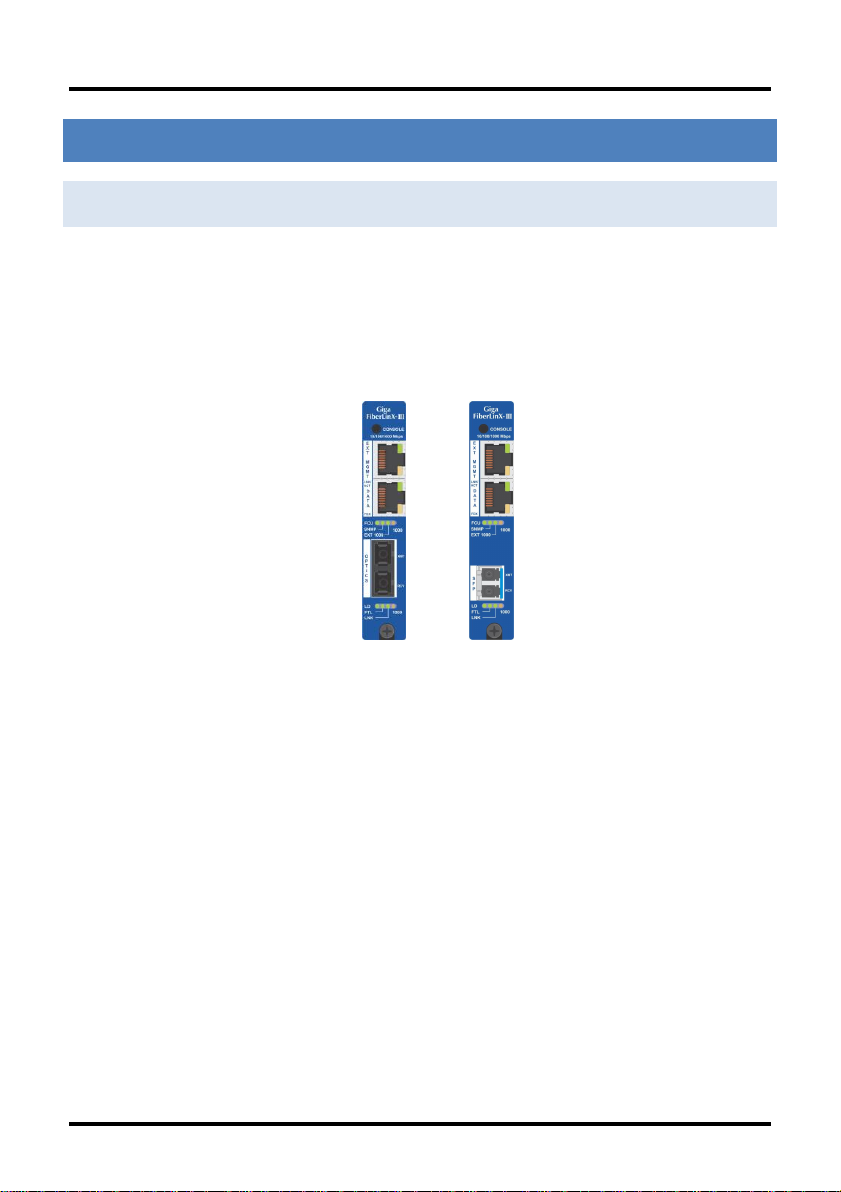
The iMcV-Giga-FiberLinX-III allows network operators to deploy managed
Ethernet services with a full range of remote management, traffic monitoring,
and alarm reporting features. The single wide module offers two fixed
10/100/1000Mbps copper ports and one fiber port in a fixed transceiver in a
variety of wavelengths for SMMM and CWDM. Another model offers an SFP port
that allows copper or fiber SFPs.
iMcV-Giga-FiberLinX-III
The iMcV-Giga-FiberLinX-III supports three main configuration modes:
Standalone, Host/Remote, or as a Host or a Remote. When using Host/Remote,
the Remote modules can be fully managed without an IP address over the fiber
optic segment. The network operator can choose to assign an IP address to the
Host or Standalone module in any mode. Or, if using a local iMediaChassis
managed chassis, all local and remotely connected iMcV-Giga-FiberLinX-III
modules can be managed using the single IP address of the chassis. This not
only preserves IP addresses and reduces configuration complexity, but
management traffic traveling on the non-IP based transmission channel is kept
isolated from customer traffic, enhancing network security.
The iMcV-Giga-FiberLinX-III offers the following features:
Securely separates the SNMP management network from the data
network
IEEE 802.1Q VLAN Tagging
Q-in-Q VLAN Extra-Tagging with EtherType (TPID) selection
Remote traffic monitoring
1
Page 7

General Information
Remote automatic alarms
Bandwidth limiting
Link Fault Pass Through (LFPT)
Loopback testing
Auto Negotiation
Selective Advertising
IEEE-802.3ah OAM support
Management through UMA
Console
The iMcV-Giga-FiberLinX-III module is a single-slot, chassis-mounted module.
Compatible chassis include the following:
iMediaChassis series
MediaChassis series
IE-MediaChassis series
PORT INTER FACES
Every iMcV-Giga-FiberLinX-III includes the following ports:
A 10/100/1000 twisted pair (RJ-45) port (EXT MGMT) for
management
One of the following ports:
One fixed 1000 Mbps Fiber port, OR
A SFP port capable of receiving a gigabit or 100Mbps fiber optic SFP
module, or a gigabit twisted pair (RJ-45) SFP module
DATA port:
A 10/100/1000 twisted pair (RJ-45) port
MANAGEMENT
Although the iMcV-Giga-FiberLinX-III provides a twisted pair port solely for
management (EXT MGMT), the iMcV-Giga-FiberLinX-III can be configured to
accept IP-based management traffic from any of its three ports. Enable
2
Page 8

General Information
Environmental
Operating temperature range: +32°F to +1°F (0°C to +50°C)
Humidity: 5% to 95%, non-condensing
Altitude: 0 to 10,000 ft.
Storage Temperature:-13°F to +158°F (-25°C to +70°C)
Power
Power Consumption (Typical): 731mA @ 5V DC
Standards /
Compliance
Read/write IEEE 802.1Q VLAN tags
QoS IEEE 802.1p-based packet prioritization (4 queues [high/low]
with 4 levels of priority)
IEEE 802.3ab 1000Base-T twisted pair
IEEE 802.3z 1000Base-X fiber
IEEE 802.3x Flow Control
IEEE 802.3i 10Base-T twisted pair
IEEE 802.3u 100Base-TX twisted pair
IEEE 802.3u 100Base-FX or SX fiber
Dimensions
Single-Slot iMcV-Module
management on more than one port, or disable management on all of the ports,
as desired. These switches limit only IP-based management. Host-to-Remote
management is IP-less and is never blocked from the fiber port. Serial port
management of the unit is available via the console port located at the top of the
module using a Mini-jack adapter.
In addition to defining which ports are used to manage the iMcV-Giga-FiberLinXIII units, the management DIP switch settings also define what ports the flow of
the Network Provider’s Management Domain traffic can take through the unit.
See Application Examples for information regarding the Management Domain.
DIP Switch 1 = ON for management on the EXT MGMT port.
DIP Switch 2 = ON for management on the DATA port.
DIP Switch 3 = ON for management on the OPTICS or UPLINK port.
SPECIFIC ATIONS
3
Page 9

Installation Instructions
CHAPTER 2: INSTALLATION INSTRUCTIONS
Each iMcV-Giga-FiberLinX-III module requires one slot in an iMediaChassis,
MediaChassis or IE-MediaChassis. To install the module in a chassis, remove the
blank faceplates covering the slots where the module is to be installed. Then
slide the module into the chassis card guides until the module is seated securely
in the connector. Secure the module to the chassis by tightening the captive
screw.
The iMcV-Giga-FiberLinX-III module includes on-board SNMP logic. A chassis
other than an iMediaChassis series cannot manage an iMcV-Giga-FiberLinX-III,
so the iMcV-Giga-FiberLinX-III must be managed independently.
When installed in an iMediaChassis, the iMcV-Giga-FiberLinX-III module can be
managed from the chassis by using the Unified Management Agent (UMA). iMcVGiga-FiberLinX-III modules not managed by UMA must have an IP address
assigned to them after installation before they can be managed. Refer to
Assigning IP Information for more information.
DIP SWITCH SELECTABL E MODE CONFIGURATION
Before installing the module in a chassis, there are two features that must be
selected using the DIP switches. These selections are:
Enable or disable management on each port
(DIP switches 1, 2, and 3)
Configure the module as a standalone, a host, or a remote
(DIP switches 7 and 8)
DIP SWITCH SETTINGS
Before installing the iMcV-Giga-FiberLinX-III, use the DIP switches to set the
hardware-configurable features. The DIP switches are located on Bay SW1 on
the iMcV-Giga-FiberLinX-III card. Refer to the diagram and table for switch
settings and available features.
DIP switch (SFP model).
4
Page 10

Installation Instructions
Switch
Function
Default
Setting
1
Management on EXT MGMT port
ON 2 Management on DATA port
OFF
3
Management on OPTICS or UPLINK port
OFF
4
Factory use – Do not change
--- 5 Factory use – Do not change
---
6
LoSPD SFP
If the model is 1x9, LoSPD is not functional
OFF
7
Remote Module
OFF 8 Host Module
OFF
HOST /REMOTE AND STAN DALONE UNITS
The iMcV-Giga-FiberLinX-III can be used as a Host, Remote, or Standalone unit.
Refer to the Application Examples section for examples.
When two iMcV-Giga-FiberLinX-III units are used as a pair, configure one as a
Host unit (DIP Switch 8 = ON) and the other as a Remote unit (DIP Switch 7 =
ON). As a host unit, the iMcV-Giga-FiberLinX-III requests management
information from the attached remote unit. It then displays that information,
along with its own, when queried by SNMP. As a Remote unit, the iMcV-GigaFiberLinX-III will respond to requests for management information from an
attached Host unit.
The iMcV-Giga-FiberLinX-III default configuration is as a Standalone unit (DIP
Switches 7 and 8 = OFF).
LOSPD
When LoSPD is set to ON, it will force the SFP mode to run at 100Mbps. If it is
set to OFF, the SFP will run at the highest usable speed determined by the SFP
itself.
MINI -SERIAL PORT
A console port, located on the front faceplate of the module, allows the customer
to use a local RS-232 serial interface for management. A special mini-jack to
DB9-F cable is provided with the product for direct connection to a PC serial port.
5
Page 11

Configuration
CHAPTER 3: CONFIGURATION
SOFTWARE CONFIGURATI ON
The following sections describe the features that can be configured.
ASSIGNING IP INFORMATION
When the iMcV-Giga-FiberLinX-III is installed in an iMediaChassis, use UMA to
manage the iMcV-Giga-FiberLinX-III without an IP address (refer to the iView²
online help for more information on UMA). When the iMcV-Giga-FiberLinX-III is
not installed in an iMediaChassis, SNMP-management is not accessible until the
iMcV-Giga-FiberLinX-III IP information (e.g., IP address, subnet mask, etc.) is
configured (using iConfig, a serial port craft connection, or DHCP). After
assigning iMcV-Giga-FiberLinX-III an IP address, use iView² or another SNMPcompatible Network Management System (NMS) to remotely configure, monitor
and manage the iMcV-Giga-FiberLinX-III.
UN I F I ED MANAGEMENT AGENT (UMA)
Centralized management makes practical sense for networks of all sizes,
especially service provider networks that must monitor and upgrade large
quantities of devices. The Unified Management Agent (UMA) allows operators to
manage all devices installed in a B&B iMediaChassis with a single IP address from
a central location. In addition, UMA allows users to centrally manage and
administer firmware upgrades over multiple devices.
AUT O NEGOTIATION, DUPLEX MODE AND SPEE D
The DATA and EXT MGMT ports on the iMcV-Giga-FiberLinX-III module Auto
Negotiate for speed and duplex. This module also provides the option of
selectively advertising or forcing the speed and duplex.
The iMcV-Giga-FiberLinX-III ships from the factory with Auto Negotiation enabled
on the twisted-pair ports. In this mode, the ports negotiate for speed and
duplex.
6
Page 12

Configuration
FOR CING THE SPEED AND DUPLEX MODE
Manually set the twisted-pair ports on the iMcV-Giga-FiberLinX-III for 10 Mbps or
100, or 1000 Mbps operation at Half- or Full-Duplex (i.e., 10 Mbps Full-Duplex,
10 Mbps Half-Duplex, 100 Mbps Full-Duplex, 100 Mbps Half-Duplex, 1000 Mbps
Full-Duplex, 1000 Mbps Half-Duplex). The Optics Port operates at 1000Mbps
Full-Duplex for fixed fiber transceivers, and can support 100Mbps as well as
gigabit fiber SFPs.
SELECTIVE ADVERTISIN G
Selective Advertising, when used in combination with Auto Negotiation,
advertises only the configured speed and duplex mode for the twisted pair port.
If a specific speed and/or duplex are desired, B&B Electronics recommends using
Selective Advertising, rather than Force Mode, when connecting to devices that
only use Auto Negotiation.
BAND W I DTH CONTROL
The iMcV-Giga-FiberLinX-III includes bi-directional bandwidth control
(configurable via iView2). This allows the bandwidth limit to be set independently
from the DATA Port to the OPTICS (or UPLINK) Port and vice versa in a single
iMcV-Giga-FiberLinX-III application. In a Host/Remote iMcV-Giga-FiberLinX-III
application, it can be set from the Host unit to the Remote unit and vice versa
(i.e., the bandwidth on the DATA ports on both the Host and Remote modules
can be limited independently).
LINK FAULT PASS THROUGH (LFPT)
Link Fault Pass Through (LFPT) is a diagnostic feature that can be enabled or
disabled. When enabled, it allows the end-user to visually detect that the Link
and the LNK LEDS will extinguish on the front faceplate of the module, when a
fault occurs. LFPT can be enabled through the SNMP software (iView²) or
serial/Telnet.
The iMcV-Giga-FiberLinX-III has three ports: Data, Optics and Ext Management.
LFPT can be enabled between any two ports. For example, if LFPT is configured
as “from” the Optics port “to” the Data port, when a fault occurs on the Optics
port, both LEDs for those ports will extinguish. The end-user can decide which
7
Page 13

Configuration
port he wants the fault to be reported to, based on which port he wants to be in
control. LFPT allows the fault to be reported down the line, through to the link
partner at the end, such as a switch or a router.
LFPT can be used in addition to setting up SNMP Traps for link up/link down.
LFPT provides a visual way to determine that link is down, and an SNMP Trap
provides a notification of a link down to a designated workstation.
LOO PBACK TESTING
The iMcV-Giga-FiberLinX-III includes Loopback testing functionality. During
loopback testing, management traffic entering the uplink port is still capable of
managing the device. This is selectable form the UNIT screen in a serial/Telnet
session or through iView².
The menu of choices in the CLI includes:
No loopback, normal traffic mode
Loopback Enabled
Loopback, Source/Destination address swap
Loopback, address swap and clear Multicast bit
No learning on fiber or Data ports
The menu of choices in iView² includes:
OFF
ON
On- Address Swap
On-Address swap + Clear MC
8
Page 14

Configuration
LOOPBACK TESTING ON REMOTE OR STANDALONE
NO LOOPBACK, NORMAL TRAFFIC MODE
The standard mode in which the units function, either as standalone or
Host/Remote.
LOOPBACK ENABLED
Loopback mode without address swap
LOOPBACK, SOURCE/DES TINATION ADDRESS SWAP
A Layer 2 Ethernet switch will discard all received packets with the same MAC
address as sent packets. To avoid this issue the Loopback feature can swap the
source and destination MAC addresses on the looped data. (This selection can
cause a frame with a multicast source address to be created, which violates the
IEEE standard.)
LOOPBACK, ADDRESS SWAP AND CLEAR MULTICAST
BIT
In addition to swapping the source and destination MAC addresses on the looped
data, the Loopback feature can also be set to clear the multicast bit. This allows
the looped data to avoid being blocked by any multicast settings.
LOOPBACK TESTING IN A HOST/REMOTE
CONFIGURATION
The iMcV-Giga-FiberLinX-III is strictly a CPE device; configuration on a Host
would require an iMcV-Giga-FiberLinX-III; select No Learning on OPTICS and
DATA Ports on the Host; on the Remote, choose SRC/DST Address Swap or
Address Swap and Clear Multicast Bit.
9
Page 15

Configuration
HOST: NO LEARNING ON OPTICS AND DATA PORTS
The Loopback feature can be set to disable address learning on the OPTICS (or
UPLINK) and DATA ports, allowing the loopback to be performed without
interference from MAC address filtering functions. This is a function on the HOST
unit. Set the REMOTE unit for Loopback then set the HOST to disable learning so
Loopback frames pass from the OPTICS port to the DATA port.
REMOTE: SOURCE/DESTINATION ADDRESS SWAP
A Layer 2 Ethernet switch will discard all received packets with the same MAC
address as sent packets. To avoid this issue the Loopback feature can swap the
source and destination MAC addresses on the looped data.
OR
ADDRESS SWAP AND CLEAR MULTICAST BIT
In addition to swapping the source and destination MAC addresses on the looped
data, the Loopback feature can also be set to clear the multicast bit. This allows
the looped data to avoid being blocked by any multicast settings.
CONFIGURATION OPTIONS
The iMcV-Giga-FiberLinX-III includes many features that are configurable via a
serial/Telnet session (CLI) or through iView² (SNMP Management view; iConfig
view).
10
Page 16

Configuration
Feature
iView²
Serial/Telnet
Loopback
Auto Negotiation
Force Mode
FlowControl
VLANs
IP Address
Subnet Mask
Default Gateway
MIB Community
Traps Assignment
Users
Passwords
Access Level
Reboot
Frame size selection
Bandwidth Limiting
OAM AH
OAM CFM
Boot Tray Delay
PROM Software
Download/Upload
Telnet Session
Software Download Setup (TFTP)
DHCP
Restore Configuration
Save Configuration
Link Fault Pass Through (LFPT)
The following options are configurable through both the iView2 (iConfig view)
and/or Serial/Telnet.
11
Page 17

Configuration
BASI C DEVICE CONFIGURATION USING THE CLI
After running through an initial self-test, the screen will display the following
message:
Press Enter for Device Configuration.
Press Enter to open the main configuration screen. This screen allows the user
to set the IP address and the destination IP address for traps with the
community string, read/write access and password as usual.
This screen contains the following information and options:
12
Page 18

Configuration
SAVED AND CURRENT VA LUES
Saved values display the changes made during the current session and current
values display the values currently in use:
IP Address (IP address of SNMP agent)
Subnet Mask (mask to define IP subnet to which agent is
connected)
Default Gateway (default router for IP traffic outside of the subnet)
DHCP
Community Strings
COMMAND LIST
I
= Enter new
P
= Change the
T
= Enter new
K
= Remove
C
= Create
U
= Delete All
E
=
End
Reboot
D
= Enable or disable
Space Bar
Saved Parameter Values
Password
Trap Destinations
All Trap Destinations
SNMP Community Strings
SNMP Community Strings
the session*
= Reboot the unit (may result in short data loss)
= Opens the device specific configuration options screen.
DHCP
*
*The screens illustrated in this manual show capabilities for users with Admin
rights. Individuals with User-level rights can only view port status and port
settings, change their password, end a session, and reboot the unit.
Note: It is necessary to reboot the iMcV-Giga-FiberLinXIII after making any modifications to the Saved Values for
the changes to take effect. To reboot, type Reboot at the
prompt on the Main Configuration screen.
13
Page 19

Configuration
ASSIGNING IP INFORMATION
To modify the Saved Parameter Values (i.e. assign IP address and subnet mask),
press I. The system prompts for the IP address and subnet mask for the
connected device. Press Enter after each entry. A default gateway can also be
assigned, or press Enter to skip. When finished, press Enter, then type reboot
for changes to take effect. The Current Values can only be saved and acted on
after the iMcV-Giga-FiberLinX-III has been successfully rebooted.
PASSWORD PROTECTION FOR SERIAL PORT
CONNECTIONS
Password/username is not offered for the serial port by default. This allows the
end user to quickly access the device for some basic configuration capability.
Password protection is provided for the serial configuration process by pressing P
on the main configuration screen. Enter a password, keeping in mind that
passwords are case-sensitive and must not exceed eight characters or include
spaces, and press Enter. This password will be requested whenever logging on.
To remove password protection, select P and, instead of entering a password,
press Enter.
Passwords have the following requirements:
The password must be between 1 and 8 characters long
The password consists of a combination of any ASCII characters
except spaces
Passwords are case sensitive
Passwords are a way to make the management of the devices secure, but
these password lists must be stored and maintained.
ASSIGNING TRAP DESTI NATIONS
Traps are sent by the manageable device to a management PC when a certain event takes
place. To enter a trap destination, press T. When prompted, enter a New IP Address
prompt, enter the appropriate IP address of the destination device and press
Then, type the name of the community string (that the destination device has been
configured to accept) and press
14
Enter
. Select whether the trap is for SNMP version 1 or
Enter
.
Page 20

Configuration
2c and press
include: Link Down, Link Up, and Last Gasp.
Enter
. This function enables ALL of the device traps. Supported traps
REMOVING TRAP DESTINATIONS
To remove all trap destinations, press K. Press Y to continue to confirm or N to abort and
remove all trap destinations. Press
This function will delete all trap destinations. To selectively delete trap destinations or to
disable/enable Traps, use iView2 (iConfig view) to configure the device. To enter another
Trap destination, repeat the steps listed above.
Enter
to finish.
CREATING COMMUNITY STRINGS
Community strings add a level of security to a network. The default community string is
named "public" and has read/write access. For security, "public" should be replaced with
custom community strings such as ones created with read-only access (for general use),
and another with read/write access (for the administrator).
To create a new community string, go to the main configuration screen and press C.
Enter the name of the new community (up to 16 characters, no spaces) and press
Then type one of the following to assign the community string’s access rights:
R = read-only access
W = read/write access
Enter
.
Enter = abort
After entering R or W, press
Enter
. To finish, press
Enter
and reboot.
DELETING COMMUNITY STRINGS
To delete all community strings, perform the following:
Press U. The "Are you sure you want to delete all community strings?" prompt is
displayed. Press Y when prompted to proceed and delete all community strings, N to
abort. Press
This function will delete ALL community strings. To selectively delete community strings,
use iView2 (iConfig view) to configure the device.
15
Enter
to finish.
Page 21

Configuration
ENDING THE SESSION
Press E to end a serial port or Telnet/HyperTerminal session before disconnecting the
serial cable. This will stop the continuous stream of data to the serial port.
REBOOTING THE UNIT
To reboot the iMcV-Giga-FiberLinX-III, type
menu.
reboot
from the main screen or the command
ENABLING/DISABLING D HCP
To toggle DHCP on the iMcV-Giga-FiberLinX-III between enable and disable, press D and
then Y. Press the
changes.
Space Bar
once to return to the main screen without making any
DHCP DISABLE (STATIC IP ADDRESSING)
DHCP is disabled in the default configuration. Initially, modules are assigned a Static
default IP Address of 10.10.10.10. Changes to the Static IP Address can be added
manually through iView2 (iConfig view), an RS-232 serial session, or a Console session.
The changes will be initiated following reboot of the module.
DHCP ENABLE (DYNAMIC IP ADDRESSING)
If a DHCP server is present on the network and DHCP is enabled, the DHCP client will
initiate a dialogue with the server during the boot up sequence. The server will then issue
an IP address to the management card. Once the new IP address is received, the SNMP
Management Module will reboot so that the new IP address will take effect. Refer to
About Serial Port Configuration for more information about Enabling/Disabling DHCP.
When there is no DHCP server on the network, use the serial configuration to manually set
the IP addresses.
When DHCP is enabled, the IP address (default 10.10.10.10 or a previously used IP
address, or user-configured) is saved. When DHCP is disabled, the saved IP address will
be reinstated and the device will reboot.
DHCP servers give out lease times: devices renew their leases based on the
administrator-specified time. If a device cannot renew its lease, and the lease expires,
the device will be given the IP address 10.10.10.10 or the previously saved IP and will
reboot.
16
Page 22

Configuration
Command
Description
cleandb
Reboots the unit with a clean database. This removes all
information from the database and sets the unit to factory
defaults.
download
Downloads firmware via the TFTP protocol
accounts
Allows the addition for User, Operator, Admin
vlan
Provides selection of three modes of operation to support all
VLAN configurations.
bw
Displays settings for Bandwidth configuration
version
Displays the unit’s firmware and hardware version
ifstats
Displays interface statistics
rmstats
Displays remote monitoring (RMON) statistics on packets
received as defined in RFC 2819 for RMON.
sysDescr
Allows the editing of sysName, sysDescr, and Port information
reboot
Allows a soft reboot of the unit after changes are made by the
end user
oam
Allows an array of OAM configurations
COM M A N DS LIST (SPACE BAR)
The iMcV-Giga-FiberLinX-III also includes several device-specific options. To access these
options, press the
action to be performed (as shown below) and press
Space Bar
from the Main Configuration screen, type the name of the
Enter
.
17
Page 23

Configuration
Command
Description
sfpstats
Provides information about the wavelength, serial number,
output power, BER and other information.
unit
Unit global settings, frame size selection. Unit OAM enable must
be enabled for AH and AG to function.
port
Displays the port status and allows changes to port settings,
such as duplex status and speed.
CLEANDB
Entering cleandb reboots the unit with its database cleaned depending on the option
selected. Users are presented with two, sequential options, first to reset all SNMP settings
and, second, to reset all of the unit’s configuration to default. Enabling the first option
presents the second. Resetting the unit to factory default values (option two) will delete
all custom IP and other configurations performed through iView², to reset the unit to the
default configuration.
DOWNLOADING FILES
Firmware and/or saved configuration data for the iMcV-Giga-FiberLinX-III can be
downloaded via a TFTP connection from a central server via TFTP protocol. Initiate this
download via serial configuration or Telnet session. To download a configuration file, type
download
displays the IP Address of the TFTP server and the name of the file to be downloaded:
and press
Enter
to be taken to the Download a file scree n. This screen
The TFTP server should be open. Press
After the transfer process is complete, press
18
Enter
to start downloading the file.
Enter
to load the configuration file:
Page 24

Configuration
User
View status, change own password, and reboot.
Operator
All User privileges mentioned above, plus ability to change settings.
Administrator
Operator privileges mentioned above, plus ability to
add/delete accounts and reinitialize the unit to default
settings (cleandb).
Once loaded into the device's SNMP memory area, the system prompts the user to
the device to make the new configuration active.
reboot
ACCOUNTS
The following are the three levels for CLI or Telnet account access:
OPERATIONAL MODE CONFIGURATION
There are three modes of operation that can be configured through the Serial/Telnet
session: Mode 1, which supports a mixture of tagged and untagged traffic, Mode 2, Extra
tagging and Mode 3, VLAN Filter.
OPERATION MODE 1 – MIXED TAGGED AND
UNTAGGED FRAMES
In this mode, all tagged and untagged frames pass on any given port. Management to
the device can be tagged or untagged.
19
Page 25

Configuration
Press the down arrow on the computer keyboard to access additional configuration
selections.
OPERATION MODE 2 PORT BASED XTRA TAGG ING
Any port can be configured for extra tags on the frames.
20
Page 26

Configuration
Press the down arrow on the computer keyboard to access the additional configuration
commands.
21
Page 27

Configuration
By default, the device is set up to access ports. However, one must be
configured to be a trunk port.
The Optics port and the Data port can be configured as an access port or a trunk
port. When configuring as a trunk port, an Ethertype can be user-defined (a
trunk port is also defined as a provider port, based on 802.1ad). If an Ethertype
value come in a trunk port and is different than the user-defined Ethertype, it
22
Page 28

Configuration
will be treated as an unrecognized VLAN tagged frame. If configuring the port as
an access port, enter a VLAN ID between 1 and 4094.
OPERATION MODE 3 VLAN FILTER
In Operation Mode 3, VLAN filters can be configured to allow passing traffic with
up to 64 separate VLAN IDs between the Optics port and the Data port. Choose
whether you want to enter a tag or no tag for management traffic. Enter up to
64 VLAN IDs in the DATA VLANs filed; VLAN IDs may be between 1 and 4094. (If
entering the value of “0”, it will disable that entry. The value of “0” is a default
setting.)
23
Page 29

Configuration
Note: It is highly recommended that customers configure
the modules to segregate management traffic from data
traffic. This is accomplished by assigning VLAN IDs. If the
traffic is not segregated, then any tests performed may
not get the expected result. By segregating the types of
traffic, the management network is secured from the
customer’s network.
BANDWIDTH (BW)
Displays settings for Bandwidth configuration.
24
Page 30

Configuration
Ingress Bandwidth
Limit
(CIR)
Monitors the traffic entering the unit (ingress),
discarding traffic that exceeds a fixed Committed
Information Rate (CIR) plus Burst Allocation (BA).
Frames are not held in queue, they either meet the
bandwidth limits and are accepted into the unit or
they are dropped.
Max Burst Allocation
size (BA)
The BA size is specified in bits; the # of bits above
the bandwidth limit before packets are thrown
away.
Ingress Burst
Allocation
Bandwidth limiting can be set at Ingress of each
port individually by setting the MAX Bandwidth
Limit in bits/sec. and the BA in bits. Traffic in
excess of the bandwidth limit plus BA for any time
interval will be dropped. This function utilizes an
advanced “Leaky Token-Bucket” algorithm to
provide typical resolution under 5% of the set
values at all data rate and frames sizes.
Egress Traffic
Shaping
Egress Traffic shaping actively controls the
transmitter and hard limits the maximum frame
rate that can be sent. Frames can be delayed in
the internal buffers of the unit, waiting their turn to
OPTICS PORT
25
Page 31

Configuration
be sent. If the internal buffers are full, excess
traffic will be dropped. The Unit Rate Control can
be used to alleviate this.
Ingress Bandwidth
Limit
(CIR)
Monitors the traffic entering the unit (ingress),
discarding traffic that exceeds a fixed Committed
Information Rate (CIR) plus Burst Allocation (BA).
Frames are not held in queue, they either meet the
bandwidth limits and are accepted into the unit or
they are dropped.
Max Burst Allocation
size (BA)
The BA size is specified in bits; the # of bits above
the bandwidth limit before packets are thrown away.
Ingress Burst
Allocation
Bandwidth limiting can be set at Ingress of each port
individually by setting the MAX BW Limit in bits/sec.
and the BA in bits. Traffic in excess of the bandwidth
limit plus BA for any time interval will be dropped.
This function utilizes an advanced “Leaky TokenBucket” algorithm to provide typical resolution under
5% of the set values at all data rate and frames sizes.
Egress Traffic
Shaping
Actively controls the transmitter and hard limits the
maximum frame rate that can be sent. Frames can
be delayed in the internal buffers of the unit, waiting
their turn to be sent. If the internal buffers are full,
excess traffic will be dropped. The Unit Rate Control
can be used to alleviate this.
OSI Level Used in
Calculations
(Open Systems
Interconnect, referring
to the seven layers for
TCP/IP)
Choose Layer 1, 2 or 3 for the counter, this will
determine how many bytes from the Ethernet frame
are to be included in the calculations.
Layer 1:
Layer 2:
Layer 3:
Preamble + DA to CRC + IFG
Frames DA to CRC
Frames DA to CRC – 18
(- 4 if frame is tagged)
DATA PORT
26
Page 32

Configuration
Explanations:
Preamble
DA
CRC
IFG
= 8 bytes
= EtherNet Destination Address
= EtherNet Checksum
= 12 bytes
Unit Rate Control
Enable/Disable
Allows the end user to globally configure all
Bandwidth settings when enabling Unit Rate Control
(Flow Control). If the END device connected to the
port also has Flow Control enabled, this will ensure
packets will not be dropped.
OSI Notes: The Bandwidth Limit functions can be
adjusted to only count the Layer 1, 2, or 3 portions of the
physical line rate. Layer 1 is used to relate Bandwidth to
the physical line rate where a 100BaseT Ethernet line can
carry a MAX bandwidth of 100Mbps. Layer 2 may be more
useful when the Ethernet Frame may be carried over
several different physical protocols such as SONET or SDH.
Only the bandwidth required by the Ethernet frame is
counted, making this a more consistent number over
different protocols. Layer 3 counting could be used when
a relationship to the actual customer data or line payload
is required. If a 10 Mbps customer file needs to be sent in
one second, then a minimum bandwidth limit of 10Mbps
would need to use Layer 3 counting to allow this.
It must be noted that only Layer 1 counting is not affected
by the size of the Ethernet frame. At 64 byte Ethernet
frames, the MAX bandwidth the line can support at Layer 2
is only 76.2% of the line rate. This maximum falls to
54.8% of the line rate when counting is further limited by
only counting Layer 3 payload data.
VERSION
Entering version will display the version of the firmware operating the iMcVGiga-FiberLinX-III.
27
Page 33

Configuration
VIEWING PORT STATISTICS (IFSTATS)
To view port statistics on the iMcV-Giga-FiberLinX-III, enter ifstats. This will
open a screen displaying information on packets received and transmitted as
defined by MIB-II standard RFC 1213.
Pressing the Space Bar will refresh the data on the screen.
VIEWING PORT RMON ST ATISTICS (RMSTATS)
To view port RMON (Remote MONitoring) statistics on the iMcV-Giga-FiberLinXIII, enter rmstats. This will display RMON information on packets received as
defined in RFC 2819 for RMON.
Pressing the Space Bar will refresh the data on the screen.
28
Page 34

Configuration
SYSTEM DESCRIPTION ( SYSDESCR)
The sysDescr allows the end-user to enter a description for the B&B Electronics
device. Within the iView² GUI, a name or some kind of identifier can be entered
into the text box labeled Description. Once that description is saved, the
identifier will be maintained, even if power is interrupted to the unit.
REBOOT
Entering reboot will save settings and reboot the iMcV-Giga-FiberLinX-III.
29
Page 35

Configuration
(OPERATION AND ADMINISTRATION MANAGEMENT) OAM
Two modes of operations control the OAM function, Passive and Active. Passive
mode is the default mode. OAM Enable is defaulted to Enable.
OAM AH passive/active is available on the fiber SFP ports and TX ports
Supports Discovery functions on the SFP ports.
Supports reporting OAM Flag Events (Link Fault, Critical Event, and
Dying Gasp)
Supports Loopback
VIEWING SFP STATISTICS (SFPSTATS)
To view SFP statistics on the iMcV-Giga-FiberLinX-III, enter sfpstats. This will
open a screen displaying SFP information, including vendor, serial number, bit
rate and other options.
Pressing the Space Bar will refresh the data on the screen.
30
Page 36

Configuration
Unit
FlowControl
Enable/Disable FlowControl functionality on the unit. This
must be enabled for FlowControl to function on any of the
ports.
UNIT
Unit FlowControl displays the following screen:
31
Page 37

Configuration
Unit Optics
Loopback
There are five selections to determine connectivity over the
fiber run.
Unit Max
Framesize
Choose from three selections of frame sizes.
Boot Trap
Delay
Seconds
When connected to a switch, such as a Cisco switch, there is a
delay time for a boot sequence (typically about 30 seconds).
Enter a value of 30 seconds or more so that the device does
not send a Trap indicating the link is down.
Unit OAM
Enable
Allows the end-user to enable or disable OAM. OAM
configuration can be set up via the CLI by accessing the
submenu and typing in the command OAM.
Port
Enable
Enable/Disable the port. (Select Enable to enable the port.)
Admin
Status
Set Administration status. (Select UP to enable/disable
management through the port.)
Po rt Configuration (port)
Serial/Telnet sessions display port status as well as allowing configuration of
some port features. Type port and press Enter to be taken to the Port screen.
From this screen, view the port speed, duplex and link status.
The Port screen contains the following commands:
32
Page 38

Configuration
Both settings must be enabled to enable the port.
Port
Speed
Ctrl
Set the port manually or for Auto Negotiation for the Twisted
Pair ports. By default, the setting is AN. A Force mode can be
selected for both speed and duplex at 10, 100 or 1000Mbps.
Advertise
Ctrl
This is the Selective Advertising feature. Selective Advertising,
when used in combination with Auto Negotiation, advertises the
configured speed and duplex mode for the twisted pair ports.
Auto Negotiation must be enabled for Selective Advertising.
Advertise
FlowCtrl
This enable/disable feature is the selection for Advertising Flow
Control. Choose this option to change based on the link
partner's capability; by default, it is enabled as Advertise Flow.
Force
FlowCtrl
This is the selection for Force Flow Control; choose this if
enabling Flow Control. You can select Force and select it to
automatically negotiate based on the link partner’s capability.
LFPT
from
This is the Link Fault Pass Through (LFPT) diagnostic function. By
default, this is disabled. You can choose any two ports to
configure LFPT in order for the device to report a failure to one
port if a fault occurs on another port.
Unit
FlowCtrl
This is the selection for enabling/disabling global flow control.
Once this is set to enabled, you can select the flow control
settings for each port as listed in the above list.
LINK FAULT PASS THROUGH (LFPT)
Link Fault Pass Through (LFPT) is a diagnostic feature that can be enabled or
disabled. When enabled, it allows the end user to visually detect that the Link
and its associated LEDS on the front faceplate of the module are not lit when a
fault occurs. LFPT can be enabled through the SNMP software (iView²) or
serial/Telnet.
The iMcV-Giga-FiberLinX-III has three ports: Data, Optics and EXT management.
LFPT can be enabled between any two ports. For example, if LFPT is configured
as “from” the Optics port “to” the Data port, then when a fault occurs on the
Optics port , both LEDs for those ports will extinguish. The end-user can decide
which port he wants the fault to be reported to, based on which port he wants to
be in control. LFPT allows the fault to be reported down the line through to the
link partner at the end, such as a switch or a router.
33
Page 39

Configuration
LFPT can be used in addition to setting up SNMP Traps for link up/link down.
LFPT provides a visual way to determine that link is down, and an SNMP Trap
provides a notification of a link down to a designated workstation.
CONFIGURATION FILE SAVE / RESTORE FUNCTION
REQUIREMENTS
The Configuration File Save/Restore Function allows a user the ability to backup
all the configuration settings of a unit. With this backup, a user can restore
settings to a unit if necessary or use this backup to apply the same settings to a
different unit.
All configurable managed objects are saved in a configuration file that is stored
in the unit’s Large File Area. This includes all configurable settings such as VLAN
configurations, IP Address configuration and SNMP agent settings. The
configuration file can be transferred from the unit to a PC and saved to disk
through the iView2 (iConfig view) utility. The configuration file can be transferred
from a PC to a unit of the same type through iView2 (iConfig view) or TFTP into
the unit’s Large File Area. After the transfer is complete, the unit copies the
configuration to flash and reboots.
The configuration file’s contents is device-type specific and can be identified by
iView2 (iConfig view) as a configuration file as well as to what type of device it is
applicable to.
SAVING A CONFIGURATION FILE TO DISK:
From the Administration Tab in iView2 (iConfig view) click the Save
Configuration button:
34
Page 40

Configuration
Save Configuration screen.
The user is prompted for a filename:
Save As screen.
The user is prompted to enter any notes to the header of the saved file for future
reference when uploading the file through iView2 (iConfig view):
Configuration Notes screen.
35
Page 41

Configuration
After the file transfer from the device to disk, the user is notified of the status:
Configuration Saved screen.
UPL OADING A SAVED CONFIGURATION FILE T HR OUGH
IVIEW2 (ICONFIG VIEW)
From the Administration Tab in iView2 (iConfig view) click the Upload
Configuration button:
Upload Configuration screen.
The user will be prompted to select a configuration file. Once selected, the user
can also view any notes that were added when the file was saved:
36
Page 42

Configuration
After selecting the configuration file, the file upload process begins; when
completed, the user is notified of the status and also notified that a reboot is
necessary for the new configuration to become active:
By design, the IP Address configuration currently on the device is kept intact and
not overwritten by the new configuration file.
37
Page 43

Operation
CHAPTER 4: OPERATION
Before using iMcV-Giga-FiberLinX-III, decide the following:
Will iMcV-Giga-FiberLinX-III units be located at only one or at both
ends of the fiber?
How will the iMcV-Giga-FiberLinX-III units be managed?
Will VLAN IDs be defined?
HOW MANY iMcV-GIGA-FIBERLINX-III UNITS WILL BE
USED?
Two for Host/Remote applications–allows IP-less management
providing greater security
One for a single unit application
One unit as a host and a Giga-AccessEtherLinX-II or IE-MultiWay as
a Remote
HOW WILL THE iMcV-GIGA-FIBERLINX-III BE MANAGED?
The iMcV-Giga-FiberLinX-III can be managed through any of its three ports (and
any combination thereof) or from the chassis. Using the EXT MGMT/OPTICS (or
UPLINK) port combination separates management traffic from the data and
provides the highest level of security. UMA management does not require an IP
address.
WILL VLAN IDS BE DEFINED?
When VLAN traffic is used with specific tags on the DATA port, it is necessary to
define VLAN IDs (refer to VLAN Operation Modes section). VLANs may be
tagged, untagged, or double-tagged.
38
Page 44

Operation
SMALL FORM-FACTOR PLUGGABLE POR TS (SFP)
iMcV-Giga-FiberLinX-III modules are available with one optional SFP port. The
SFP port can support a 100Mbps or 1000Mbps fiber SFP. It can also support a
1000Mbps or 10/100/1000Mbps copper SFP. SFPs must be MSA-compliant, with
or without Digital Diagnostics Monitoring Interface (DDMI). The SFP port will
accept third-party SFPs. DDMI statistics provide real-time access to transceiver
operating parameters such as voltage, temperature, laser bias current, and both
transmitted and received optical power. DDMI information can be accessed in
iView2 by clicking Tables > SFP Info.
Note: iMcV-Giga-FiberLinX-III has been tested
with the B&B Electronics SFP modules. You can
install any MSA-compliant SFP module. However,
B&B Electronics does not guarantee the
functionality of non- B&B Electronics SFP modules
due to possible non-conformity with MSA design
standards.
39
Page 45

LED Operation
Diagnostic LEDs
FCU (Far CPU Up):
Host: Glows green
when far end is
detected.
Remote: Glows green
when unit is
configured as Remote.
Standalone Unit: LED
remains OFF.
SNMP
:
This LED glows green
to indicate that this is
an SNMP manageable
module.
EXT 1000
:
Glows green when EXT
MGMT port is
operating at 1000
Mbps.
1000
:
Glows green when the
fiber is operating at
1000 Mbps.
Optics Port LEDs
LD:
Glows green when “light” is
detected on fiber input.
FTL (Far TX Link):
Host: Glows green when a
link is established on
remote (far-end) DATA
port.
Remote: Glows green when
unit is configured as
Remote.
Standalone: LED remains
OFF.
LNK (Link):
Glows green when link is
established on port.
1000:
Glows green when the
fiber is operating at 1000
Mbps.
CHAPTER 5: LED OPERATION
The iMcV-Giga-FiberLinX-III features diagnostic LEDs as shown below.
TX/FX LEDS
40
Page 46

LED Operation
Diagnostic LEDs
FCU (Far CPU Up):
Host: Glows green
when far end is
detected.
Remote: Glows green
when unit is
configured as Remote.
Standalone Unit: LED
remains OFF.
SNMP:
This LED glows green
to indicate that this is
an SNMP manageable
module.
EXT 1000:
Glows green when
EXT MGMT port is
operating at 1000
Mbps.
1000:
Glows green when the
fiber is operating at
1000 Mbps.
Optics Port LEDs
LD:
Glows green when
“light” is detected on
fiber input.
FTL:
Host: Glows green when
a link is established on
remote (far-end) DATA
port.
Remote: Glows green
when unit is configured
as Remote.
Standalone: LED remains
OFF.
LNK (Link):
Glows green when link is
established on port.
1000:
Glows green when the
fiber is operating at 1000
Mbps; no LED for
100Mbps SFP.
TX/SFP LEDS
41
Page 47

Troubleshooting
CHAPTE R 6: TROUBLESHOOTING
If two iMcV-Giga-FiberLinX-III Host/Remote units are not communicating
properly, make sure one is a Host and the other is a Remote. If the second unit
is not configured as a Remote, it will be recognized as a Standalone unit and the
Host and Remote units will not communicate with each other properly. Setting
the OPTICS port management DIP Switch 3 to the ON position on both modules
will allow performing a simple PING test. This is possible only if PINGing from
the computer through the optics uplink port, which is highly unusual. The EXT or
data switch must be enabled and connected to the computer to ping either
device.
If a link on a twisted pair port cannot be established, make sure the cable is in
working order; if not, replace the cable (iMcV-Giga-FiberLinX-III includes AutoCross; a link should be detected regardless of the CAT5 cable type).
If a fiber link cannot be established, make sure that the fiber transceivers on
iMcV-Giga-FiberLinX-III are not over/under driving the fiber receivers. Make
sure the fiber mode and wavelength on both iMcV-Giga-FiberLinX-III units match
(i.e., both are 1310 nm single-mode fiber).
Make sure the port speeds on iMcV-Giga-FiberLinX-III match those on the end
devices connected to iMcV-Giga-FiberLinX-III. B&B Electronics recommends
configuring all connected devices to Auto Negotiation, or if using Force mode,
ensure speed and duplex settings match.
If using single-strand fiber, make sure the pair of devices is compatible single-
strand fiber devices. For example, an iMcV-Giga-FiberLinX-III TX/SSFX-SM1310SC which transmits 1310 nm and receives 1550 nm must be connected to a
device which transmits 1550 nm and receives 1310 nm.
If using an iMcV-Giga-FiberLinX-III unit with an SFP port and it is not functioning
properly or at all, make sure that the installed SFP module is the correct speed
(1000 Mbps).
If management is not functioning properly, make sure that the DIP Switch
settings are accurate for the port to be managed.
To restore the unit to factory default settings, use the cleandb function via the
serial port (refer to the Device-Specific Options from the Command Line section
for more information). This is especially helpful if the module may have been
configured improperly. If restarting to factory defaults is necessary, B&B
42
Page 48

Troubleshooting
Electronics recommends using this function on both units in Host/Remote
applications, then reconfiguring all settings.
Ensure READ/WRITE Community Strings for iMcV-Giga-FiberLinX-III and iView²
are the same.
Ensure none of the twisted-pair ports on the iMcV-Giga-FiberLinX-III are
connected to the twisted-pair port on the Management Module in an
iMediaChassis series chassis.
THE AGENT INFO SCREE N
Information about the SNMP Agent software managing the iMcV-Giga-FiberLinXIII is contained on this screen.
43
Page 49

Fiber Optic Cleaning Guidelines
CHAPTER 7: FIBER OPTIC C LEANING GUIDELINES
Fiber Optic transmitters and receivers are extremely susceptible to
contamination by particles of dirt or dust, which can obstruct the optic path and
cause performance degradation. Good system performance requires clean optics
and connector ferrules.
1. Use fiber patch cords (or connectors, if you terminate your own
fiber) only from a reputable supplier; low-quality components can
cause many hard-to-diagnose problems in an installation.
2. Dust caps are installed by the manufacturer to ensure factory-clean
optical devices. These protective caps should not be removed until
the moment of connecting the fiber cable to the device. Should it
be necessary to disconnect the fiber device, reinstall the protective
dust caps.
3. Store spare caps in a dust-free environment such as a sealed
plastic bag or box so that when reinstalled they do not introduce
any contamination to the optics.
4. If you suspect that the optics have been contaminated, alternate
between blasting with clean, dry, compressed air and flushing with
methanol to remove particles of dirt.
44
Page 50

Appendix A: iView2 Management Software
APPENDIX A: IVIEW2 M AN AGEMENT SOFTWARE
iView² is the management software that features a Graphical User Interface
(GUI) and gives network managers the ability to monitor and control the
manageable B&B Electronics products.
iView² is available in several versions, including a WebServer version 3.0, and
can also function as a snap-in module for HP OpenView Network Node Manager
and other third party SNMP Management software.
iView2 supports the following platforms:
Windows 2000
Windows XP
Windows Vista
Windows 7
Please see the SNMP Management Module manual for software configuration
options.
IVIEW2 (ICONFIG VIEW)
iView2 (iConfig view) is an in-band utility used for SNMP configuration for B&B
Electronics’ SNMP-manageable devices.
The iView2 (iConfig view) feature allows the following to be performed:
Set an IP address, subnet mask and default gateway
Define community strings and SNMP Traps
iView2 (iConfig view) also includes an authorized IP address system and
restricted access to MIB groups which are supported by B&B Electronics'
manageable devices. These extra layers of security do not affect SNMP
compatibility. iView2 (iConfig view) can upload new versions of the system
software and new MIB information. It also includes diagnostic capabilities for
faster resolution of technical support issues.
45
Page 51

Appendix A: iView2 Management Software
US I N G IVIEW
iView² is management software that provides network management in an easy
to use GUI. Once iView² is installed on a network management PC using a
Windows operating system, use the Start menu to access iView².
Note: Windows SNMP services must be installed to receive
Traps.
The autoscan feature of iView² will detect B&B Electronics devices on an active
subnet and list them in the network outline. Click the connection for the iMcVGiga-FiberLinX-III to open its iView² screen. To perform additional configuration,
select the iView2 iConfig view icon on the toolbar in iView². This allows a session
to be launched, and the default password/username is admin/admin. Additional
private usernames and passwords can be entered in the USERS tab. If the list of
passwords is not maintained, the usernames and passwords can be reset by
opening a CLI session and typing in the cleandb command. This will reset all but
the IP address of the device.
2
iView2 main screen.
46
Page 52

Appendix A: iView2 Management Software
Function
Description
Unit
Configuration
Display/modify unit information
Port
Configuration
Display/modify port data
Bandwidth
Displays settings for Bandwidth configuration
Tables
Display statistics tables, including Unit and Port tables,
RMON statistics, MIB-II ifTable and SFP Info.
VLAN
Provides configuration for VLAN IDs per port
Advanced
Reboot the module; also allows boot trap delay
OAM AH
Configure passive and active 802.3ah
OAM CFM
Perform 802.1ag for connectivity fault management
Agent Info
Displays SNMP agent data
The following functions can be performed via iView2:
UNIT CONFIGURATION
Select Unit Configuration to display/modify unit information, including IP address
(display only, modification available through iConfig), global flow control,
maximum frame size, and OAMPDU. The Unit Configuration is available within
the Host Config settings and the Remote Config settings.
47
Page 53

Appendix A: iView2 Management Software
Host Configuration screen.
Remote Configuration screen.
48
Page 54

Appendix A: iView2 Management Software
BANDWIDTH
Select Bandwidth to display configured bandwidth settings for the DATA or the
Optics port.
Bandwidth Configuration screen.
TABLES
Select tables to display a screen on which you can extract SFP information,
RMON statistics, Unit and Port Tables, or MIB-II ifTable.
49
Page 55

Appendix A: iView2 Management Software
Tables main screen.
Select Unit and Port Tables to display the following information: the link status, if
the port is enabled/disabled, SNMP status, speed status on each port and other
vital statistics.
Unit and Port Tables screen.
50
Page 56

Appendix A: iView2 Management Software
VLAN
Enter a VLAN ID between 1 and 4,094; possible priority settings are 0 (lowest
priority) through 7 (highest priority).
VLAN Configuration screen showing Operation Mode 1.
VLAN Configuration screen showing Operation Mode 2.
51
Page 57

Appendix A: iView2 Management Software
NOTE: the VLAN configuration only applies to the Host. The Remote unit must be
accessed directly via a separate IP address or through Telnet.
VLAN Configuration screen showing Operation Mode 3.
ADVANCED
Select Advanced button to upgrade a Host/Remote unit and reset the Host or
Remote or set the Boot Trap Delay.
Advanced screen.
52
Page 58

Appendix A: iView2 Management Software
OAM AH
Select OAM AH to display the following screen and monitor the status,
configuration, loopback, event log and statistics.
OAM AH screen.
From the above screen, select Configuration to display state and event
configuration information as well as OAM supported functions:
OAM AH: Configuration screen.
53
Page 59

Appendix A: iView2 Management Software
LOOPBACK TESTING
The iMcV-Giga-FiberLinX-III includes Loopback testing functionality. This feature
is selectable via iView2 within the OAM AH configuration. The menu of choices
for all ports includes:
Terminate/initiate
Process/ignore
OAM Loopback is controlled by using the “Loopback” and “Ignore Rx” control
parameters. Selecting “Initiate” from the “Loopback” control tells the client to
start a loopback process with the peer. Selecting “Process” from the “Ignore Rx”
control tells the client to process received loopback commands.
Only AH “Active” units can send a Loopback command to a remote unit. Either
Active or Passive AH units can respond to a Loopback command, but must be
configured to process these commands or they will be ignored.
Select Loopback to display loopback data and define how loopback is configured:
OAM AH: Loopback screen.
54
Page 60

Appendix A: iView2 Management Software
Select Event Log to display the OAM event log showing fault changes that have
occurred via OAM configuration:
OAM AH: Event Log screen.
The OAM Event Log table displays a history of the threshold crossing events and
non-threshold crossing events that have occurred at the Ethernet OAM AH Level.
There is a maximum of 8 events that can be displayed. When the maximum
number of events is reached older entries are deleted to make room for newer
entries.
Select Statistics to display OAM statistics:
OAM AH: Statistics screen.
55
Page 61

Appendix A: iView2 Management Software
OAM CFM
Select OAM CFM to display the following screen and perform administrative
control for Maintenance Domains (MDs), Maintenance Assocations (MAs) and
Maintenance Association End Points (MEPs). The page contains a list of the local
MEPs and provides menu controls to access the administrative functions
associated with Create, Delete, and List MD, MA, and MEP information. An
example of a default OAM CFM Configuration page is shown below:
OAM CFM: Configuration screen.
The OAM CFM Configuration page defaults to the “Configure MEP” selections.
OAM CFM: MEP Screen.
56
Page 62

Appendix A: iView2 Management Software
For the first-time configuration, the user must first create an MD, then an MA,
then local and peer MEPs can be added. To create an MD, select the "Configure
MD' button to display the OAM CFM Maintenance Domain Configuration page as
shown below:
OAM CFM: Maintenance Domain Configuration screen.
NOTE: iView2 will automatically display this page if there
is no MD yet defined when the user attempts to access
any other menu control.
Enter the MD name and select the level for the domain. To cancel the MD, select
Delete. To store the MD, press Save and the screen is refreshed.
57
Page 63

Appendix A: iView2 Management Software
For the first configuration, create an MA after the MD. Select "Configure MA" to
display the OAM CFM Maintenance Association Configuration screen as shown
below:
OAM CFM: Maintenance Association Configuration screen.
NOTE: iView2 will automatically display this page if there
is no MD yet defined when the user attempts to access
any other menu control.
Select the Domain and Format, and enter the MA name in the Name field. Use
Interval to select the interval for continuity check messaging, and choose
Primary VID, if applicable. To cancel the MA without saving, select Delete. To
store the MA, select Save and the screen is refreshed.
58
Page 64

Appendix A: iView2 Management Software
For a first time configuration, the next step is to create a MEP. Select Add New
MEP to display the OAM CFM MEP configuration page as shown below:
OAM CFM: MEP Configuration screen.
Select the MD, MA, enter the MEP ID, select the appropriate type, port and
direction, and select the Primary VID, if applicable. To cancel the MEP without
saving, select Delete. To store the MEP, select Save and the screen is
refreshed.
59
Page 65

Appendix A: iView2 Management Software
Color
Description
Green
Correctly functioning MEP—all MEP’s are active and sending CCMs
Red
Idle state or problem associated with the MEP
Yellow
Not all peer MEP CCMs are being received.
Once the user has configured the MD, MA and at least one MEP, a particular
instance of an MEP can be accessed for more detailed configuration. To access a
particular instance of an MEP, click on the row containing the desired MEP as
shown below:
OAM CFM: MEP Configuration screen: MEP selected.
The current state of the MEP is shown by the color in the "State" column.
Moving the mouse over the displayed color displays a comment giving additional
information about the current state. Valid comments are:
MEP is Idle
MEP is Active
Remote MEP Idle
Remote MEP Failed
60
Page 66

Appendix A: iView2 Management Software
Function
Description
Continuity
Check
Enable/disable CCMs and verify the number of CCMs that
have been sent.
Instance
State Details
Verify the current administrative state of the MEP, view the
last defect identified by the MEP, and view the MAC address
of the MEP.
Peer MEPs
Create/List/Delete Peer MEPS associated with the MEP
Loopback
Activate loopback and see the results of loopback
operations.
The MEP Instance Configuration page offers more details about an individual MEP
as shown below:
OAM CFM: MEP Instance Configuration screen.
From this screen, the user can perform the following functions:
Select Data Analysis to perform a channel line rate test, a round trip delay test,
and a return to the main OAM CFM screen by selecting OAM CFM.
61
Page 67

OAM CFM: Data Analysis screen.
AGENT INFO
Select Agent Info to display agent data:
Appendix A: iView2 Management Software
Agent Info screen.
62
Page 68

APPENDIX B: PINOUTS
The following table lists the pin
configuration for the RJ-45 Data
connector.
Pin
Signal Name
1000M
Signal Direction
10/100M
1
TXD1+
Out*
2
TXD1-
Out*
3
RXD2+
In* 4 D3+ 5
D3- 6
RXD2-
In*
7
D4+
8
D4-
Pin
DB9-F Pin#
Signal Name
Direction
Tip 2 Transmit
Out of Unit
Ring 3 Receive
In to Unit
Sleeve 5 Return
Return
Pin 1
RJ-45 DATA PORT PINOUT
NOTE: The MDI/MDIX function will automatically adjust
the direction of these signals to match the connected unit
when running 10/100Base-T. 1000Base-T will use all 4
pairs in full duplex mode.
Appendix B: Pinouts
RS-232 SERIAL CONSOLE PORT
The following table lists the pin configuration for the RS-232 3-pin Mini Jack
mating connector for the console serial port.
63
Page 69

Appendix C: Troubleshooting
APPENDIX C: TROUBLESHOOTING
If a fiber connection cannot be established, perform the following to make sure
that the fiber transceivers on the iMcV-Giga-FiberLinX-III are not over/under
driving the fiber receivers:
1. Make sure the fiber wavelength on both connected devices match
(i.e. both are 1310 nm single-mode fiber).
2. Make sure the twisted-pair port speed on the iMcV-Giga-FiberLinX-
III matches that of the end devices connected to the iMcV-GigaFiberLinX-III. Configure the iMcV-Giga-FiberLinX-III and its link
partner to Auto Negotiation or, if using Force mode, be sure speed
and duplex match.
3. iMcV-Giga-FiberLinX-III allows the end user to assign a VLAN tag to
all management traffic (SNMP and telnet). It is important to
understand that IF using telnet or iView2 to assign a VLAN tag to
management traffic then as soon as this setting is saved the
connectivity will be lost until the PC becomes a member of the
VLAN which was assigned to management traffic.
4. If a VLAN tag has been assigned to management traffic and the end
user cannot re-establish a connection to the device via iView2 or
telnet, directly connect a PC to the device via the serial cable and
review/modify the changes made (reference section on serial port
config).
64
Page 70

Appendix D: Unified Management Agent (UMA)
APPENDIX D: UNIFIED MANAGEMENT AGENT
(UMA)
UMA operates in conjunction with B&B Electronics devices with on-board
intelligence (e.g., the iMcV-Giga-FiberLinX-III and the iMediaChassis series. For
example, install 20 devices in the chassis at the Central Office (CO), then
connect each to a remote iMcV-Giga-FiberLinX-III unit installed at the customer's
premise (CPL); UMA will then allow users to manage all 40 devices (including the
chassis at the CO) via a single IP address. Users may still assign IP addresses to
each iMcV-Giga-FiberLinX-III and manage them independently when the SNMP
Management Card within the iMediaChassis is omitted.
WITH THE UNIFIED MANAGEMENT AGENT
When an SNMP request for a iMcV-Giga-FiberLinX-III comes in, the SNMP
Management Card in the iMediaChassis passes the request to the SNMP agent in
the specific module. The SNMP agent in the iMcV-Giga-FiberLinX-III provides the
relevant management information which is then routed via the SNPM
Management Card and supplied to the client GUI (iView2).
WITHOUT THE UNIFIED MANAGEMENT AGENT
When an SNMP request for an iMcV-Giga-FiberLinX-III comes in, the
iMediaChassis cycles through each slot checking for iMcV-Giga-FiberLinX-III
modules. The iMediaChassis sees the first iMcV-Giga-FiberLinX-III modules in
the chassis, and they can be selected, but they cannot be managed; the full
management interface is inaccessible. Management for each iMcV-GigaFiberLinX-III requires a separate connection and a separate IP address.
EASY UPGRADES WITH T HE UNIFIED MANAGEMENT
AGENT
Upgrade one or multiple Host (CO) or Remote (CPE) devices with
just a few mouse clicks
All devices in chassis are fully functional while upgrades are in
process
65
Page 71

Appendix D: Unified Management Agent (UMA)
Manage up to 41 devices with a single IP address
Telnet capability available for all devices
Conserve usage of switch ports; separate SNMP connections for
installed devices are not required
66
Page 72

Appendix E: Glossary
Term/Acronym
Definition
802.1ag
IEEE standard for end-to-end OAM
802.3ah
IEEE standard addressing Ethernet in the first mile and also
OAM for point-to-point Ethernet links.
CFM
Connectivity Fault Management
CLI
Command Line Interface: An interface screen used for
system management and diagnostics requiring the user to
type commands rather than use a GUI.
CPE
Customer Premises Equipment; normally the end point of a
leased fiber.
DC
Direct Current
DDMI
Digital Diagnostic Monitor Interface: A defined serial
interface and data format typically used to access SFP
internal information
DHCP
Dynamic Host Configuration Protocol: Used to automate
configuration of computers that use TCP/IP
GUI
Graphical User Interface: Software that provides a visual
interface to enable an end-user to manage and monitor
network devices.
IEEE
Institute of Electrical and Electronics Engineers; IEEE
develops industry-wide standards for use in a variety of
electronic devices
IP
Internet Protocol
LED
Light Emitting Diode: a light to indicate link, duplex or other
options.
MA
Maintenance Association
MD
Maintenance Domain
APPENDIX E: GLOSSARY
The following are terms and phrases used within this manual, or which are found
in documents associated with this equipment.
67
Page 73

Appendix E: Glossary
Term/Acronym
Definition
MDI/MDIX
Media-Dependent Interface/ Media-Dependent Interface
Crossover. The ability of an Ethernet port to automatically
detect and configure its cabling connections to
accommodate crossover or non-crossover wiring, depending
on its link partner and cabling.
MEP
Maintenance Association End Points
MIB
Management Information Base: A database of objects that
can be monitored by a network management system. Both
SNMP and RMON use standardized MIB formats that allow
any SNMP and RMON tools to monitor any device defined by
a MIB.
MSA
Multi-Source Agreement (SFP): The standard an SFP must
meet to be compatible in network devices.
NOC
Network Operations and Control Center
OAM
Operations, Administration and Maintenance
OAM CFM
IEEE 802.1ag Connectivity Fault Management
PROM
Programmable Read-Only Memory
SFP
Small Form-Factor Pluggable: An industry standard optical
pluggable module.
SNMP
Simple Network Management Protocol: A set of protocols
for managing complex networks over a standards-based IP
network.
TFTP
Trivial File Transfer Protocol
VLAN
Virtual Local Area Network
68
 Loading...