

Page 1
MMccPPCC MMeeddiiaaLLiinnXX
((PPCCII aanndd LLooww PPrrooffiillee PPCCII VVeerrssiioonn))
RRXX//TTXX VVeerrssiioonnss
CCoommppaacctt MMeeddiiaa CCoonnvveerrtteerrss
Page 2
International Headquarters
B&B Electronics Mfg. Co. Inc.
707 Dayton Road
Ottawa, IL 61350 USA
Phone (815) 433-5100 -- General Fax (815) 433-5105
Website: www.bb-elec.com
support@bb-elec.com
European Headquarters
B&B Electronics
Westlink Commercial Park
Oranmore, Co. Galway, Ireland
Phone +353 91-792444 -- Fax +353 91-792445
Website: www.bb-europe.com
techsupport@bb-elec.com
© 2013 B&B Electronics – Revised Aug 2013
2
Page 3

Table of Contents
FCC RADIO FREQUENCY INTERFERENCE STATEMENT ......... 4
WARRANTY ............................................................................................... 4
ABOUT THE MCPC MEDIALINX ........................................................ 4
INSTALLING THE MCPC .................................................................................... 6
HARDWARE MOUNTING .................. ERROR! BOOKMARK NOT DEFINED.
POWERING THE MCPC ..................... ERROR! BOOKMARK NOT DEFINED.
LED OPERATION .............................................................................................. 9
SPECIFICATIONS ................................................................................. 11
FIBER OPTIC CLEANING GUIDELINES ...................................... 12
ELECTROSTATIC DISCHARGE PRECAUTIONS ........................ 13
SAFETY CERTIFICATIONS ................................................................ 14
3
Page 4

FCC RADIO FREQUENCY INTERFERENCE
STATEMENT
This equipment has been tested and found to comply with the limits for a C lass B computing device, pursuant to
Part 15 of th e FCC Rules. These limits are design ed to provide r easonable prot ection against h armful interferen ce
when the equipmen t is operated in a commercial enviro nment. This equipment generates , uses and can radiate
radio frequency energy and, if not installed and used in accordance with the instruction manual, may cause harmful
interferenc e to radio communica tions. Operatio n of this equ ipment in a resid ential area is likely to cau se harmful
interference in which the user will be required to correct the interference at his own expense.
Any changes o r m odifications not expressly approved by the manufacturer could void the user’s authority to operate
the equipment.
The use of non-shielded I/O c ab les ma y no t gu ar ant ee co mp lianc e wit h FCC R FI lim its . This d igit al apparatus does
not exceed the Class B limits for radio noise emission from digital apparatus set out in the Radio Interference
Regulation of the Canadian Department of Communications.
Le présent ap pareil nu mériq ue n’émet pas de b ruit s ra dioélectr iques dépa ss ant les lim ites ap plic ab les a ux a pp ar eils
numériques de c lasse B prescrites d ans le Règlement sur le br ouillage radioélec trique publié par le m inistère des
Communications du Canada.
WARRANTY
Limited Lifetime Warranty
Effective for products of B&B Electronics Manufacturing Company shipped on or after
May 1, 2013, B&B Electronics Manufacturing Company warrants that each such product
shall be free from defects in material and workmanship for its lifetime. This limited
lifetime warranty is applicable solely to the original user and is not transferable.
This warranty is expressly conditioned upon proper storage, installation, connection,
operation and maintenance of products in accordance with their written specifications.
Pursuant to the warranty, within the warranty period, B&B Electronics Manufacturing
Company, at its option will:
1. Replace the product with a functional equivalent;
2. Repair the product; or
3. Provide a partial refund of purchase price based on a depreciated value.
4
Page 5

Products of other manufacturers sold by B&B Electronics Manufacturing Company are
not subject to any warranty or indemnity offered by B&B Electronics Manufacturing
Company, but may be subject to the warranties of the other manufacturers.
Notwithstanding the foregoing, under no circumstances shall B&B Electronics
Manufacturing Company have any warranty obligations or any other liability for: (i) any
defects resulting from wear and tear, accident, improper use by the buyer or use by any
third party except in accordance with the written instructions or advice of the B&B
Electronics Manufacturing Company or the manufacturer of the products, including
without limitation surge and overvoltage conditions that exceed specified ratings, (ii)
any products which have been adjusted, modified or repaired by any party other than
B&B Electronics Manufacturing Company or (iii) any descriptions, illustrations, figures as
to performance, drawings and particulars of weights and dimensions contained in the
B&B Electronics Manufacturing Company’s catalogs, price lists, marketing materials or
elsewhere since they are merely intended to represent a general idea of the products
and do not form part of this price quote and do not constitute a warranty of any kind,
whether express or implied, as to any of the B&B Electronics Manufacturing Company’s
products.
THE REPAIR OR REPLACEMENT OF THE DEFECTIVE ITEMS IN ACCORDANCE WITH THE
EXPRESS WARRANTY SET FORTH ABOVE IS B&B ELECTRONIC MANUFACTURING
COMPANY’S SOLE OBLIGATION UNDER THIS WARRANTY. THE WARRANTY CONTAINED
IN THIS SECTION SHALL EXTEND TO THE ORIGINAL USER ONLY, IS IN LIEU OF ANY AND
ALL OTHER WARRANTIES, EXPRESS OR IMPLIED, AND ALL SUCH WARRANTIES AND
INDEMNITIES ARE EXPRESSLY DISCLAIMED, INCLUDING WITHOUT LIMITATION (I) THE
IMPLIED WARRANTIES OF FITNESS FOR A PARTICULAR PURPOSE AND OF
MERCHANTABILITY AND (II) ANY WARRANTY THAT THE PRODUCTS ARE DO NOT
INFRINGE OR VIOLATE THE INTELLECTUAL PROPERTY RIGHTS OF ANY THIRD PARTY. IN
NO EVENT SHALL B&B ELECTRONICS MANUFACTURING COMPANY BE LIABLE FOR LOSS
OF BUSINESS, LOSS OF USE OR OF DATA INTERRUPTION OF BUSINESS, LOST PROFITS OR
GOODWILL OR OTHER SPECIAL, INCIDENTAL, EXEMPLARY OR CONSEQUENTIAL
DAMAGES. B&B ELECTRONIC MANUFACTURING COMPANY SHALL DISREGARD AND
NOT BE BOUND BY ANY REPRESENTATIONS, WARRANTIES OR INDEMNITIES MADE BY
ANY OTHER PERSON, INCLUDING WITHOUT LIMITATION EMPLOYEES, DISTRIBUTORS,
RESELLERS OR DEALERS OF B&B ELECTRONIC MANUFACTURING COMPANY WHICH ARE
INCONSISTENT WITH THE WARRANTY, SET FORTH ABOVE.
5
Page 6

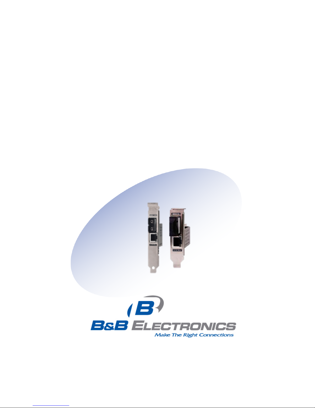
ABOUT THE MCPC MEDIALINX
Part Numbers: 855-12733-RX, 855-12733-TX
855-15733-RX, 855-15733-TX
The above part numbers must be installed in pairs. As a pair,
the units provide secure data to be passed in one direction
only.
The McPC MediaLinX provides a single conversion between
10/100 Base-T twisted pair and 100 Base-SX/FX fiber. This
device Auto Negotiates speed and duplex on the copper port
and the fiber 100Mbps, FDX. The media converter supports
jumbo frames up to 1916 MTU.
The McPC MediaLinX is a fixed f iber transceiver model, includes
one 10/100Mbps RJ-45 connector and one 100Mbps SC fiber
connector which c a n support Multi Mode fiber. One model offers
a PCI bracket, the other model offers low profile PCI bracket,
and both must be installed in a PCI slot in a PC. No drivers are
required for this product line; it converts from fiber to copper
and uses a 4-pin periphera l power supply connector.
INSTALLING THE MCPC
Offering pl u g-and-play ope ra ti on, t he McP C MediaLinX comes ready to
install, utilizing power from the PC’s moth er boa r d. To i ns t all t he Mc P C
MediaLinX
1.
Turn off the PC
2.
Remove i t s cover
3.
Find an empt y P CI sl ot
4.
Align the McPC MediaLinX in the slot
5.
Screw the the McPC MediaLinX into the computer casing’s bracket
6.
Make sure the McPC MediaLinX does no t ext e n d pa st t he ed g e o f
the case
7.
Attach th e key e d mi ni -p ow er connector to the McPC MediaLinX
6
Page 7

8. Attach th e mal e en d of the “Y” conn ec t or to on e of t h e com pu ter’s
standard size power connectors
9.
Replace the cover
10.
Attach th e ca bl es b et w e en t he McPC MediaLinX) and t he d evi c es
that will be co nnected
7
Page 8

AUTOCROSS
Whether using a crossover or straight-through CAT 5 twisted pair cabling, the
McPC MediaLinX will support both types of connections with AutoCross, a
feature that automatically selects between a crossover workstation or pass-
through connection depending on the connected device.
PCI Bracket
Low Profile Bracket
8
Page 9

LED OPERATION
Each McPC MediaLinX includes two LEDs, located on the RJ-45
connector. LED functions are as follows for the TX Unit:
FX TX
FX LNK/AC T Glows green when a link is established on the FX (fiber)
port; blinks green when activity is detected on the fiber
port.
Although the copper and fiber ports may not be
physically conne c ted, the FX (fiber ) port will alw ays
show a green LED, as the link is forced ON, to ensure
the connection.
TX LNK/ACT Glows green when a link is established on the TX
(copper) port; blinks green when activity is detected on
the copper port.
9
Page 10

Each McPC MediaLinX includes two LEDs, located on the RJ-45
connector. LED functions are as follows for the RX Unit:
FX TX
FX LNK/AC T Glows green when a link is established on the FX (fiber)
port; blinks green when activity is detected on the fiber
port.
TX LNK/ACT Glows green when a link is established on the
TX(copper) port; blinks green when activity is detected
on the copper port.
10
Page 11

SPECIFICATIONS
Ethernet Connections
• 10/100 BaseT
• Auto Negotiation
• AutoCross
• Flow Control
• 1916 MTU
• Full Line-Rate Forwarding
Operating Temperature
+14°F to +122°F (-10C° to +50°C)
Storage Temperature
-31°C to +167° F (-35C° to +75°C)
Humidity
5% to 95% (non-condensing), 0 – 10,000 ft. altitude
Input Power Consumption (Typical)
7 mA @ 5 VDC
11
Page 12

FIBER OPTIC CLE ANING GUIDELINES
Fiber Opt ic transmitters and rec eivers are e xt r e m ely susceptible
to contamination by particles of dirt or dust, which can obstruct
the optic path and cause performance degradation. Good
system performance requires clean optics and connector
ferrules.
1. Use fiber patch co rds (or connectors, if you te rminate your
own fiber) only from a reputable supplier; low-quality
components can cause many hard-to-diagnose problems in
an installation.
2. Dust caps are installed at B&B Electronics to ensure fact or yclean optical devices. These protective caps should not be
removed until the moment of connecting the fiber cable to
the device. Should it be necessary to disconnect the fiber
device, reinstall the protective dust caps.
3. Store spare caps in a dust-free environment such as a
sealed plastic bag or box so that when reinstalled they do
not introduce any contamination to the optics.
4. If you suspect that the optics have been contaminated,
alternate between blasting with clean, dry, compressed air
and flushing with methanol to re move particles of dirt.
12
Page 13

ELECTROST ATIC DISCHARGE PRECAUTIONS
Electrostatic discharge (ESD) can cause damage to any
product, add-in modules or standalone units, containing
electronic components. Always observe the following
precautions when installing or handling these kinds of products
1. Do not remove unit from its protective packaging until
ready to install.
2. Wear an ESD wrist grounding strap before handling any
module or component. If the wrist strap is not available,
maintain grounded contact with the system unit throughout
any procedure requiring ESD protection.
3. Hold the units by the edges; do not touch the electronic
components or gold connectors.
4. After removal, always place the boards on a grounded,
static-free surface, ESD pad or in a proper ESD bag. Do not
slide the modules or standalone units over any surface.
WARNING!
Integrated circuits and fiber optic
components are extremely susceptible to
electrostatic discharge da
mage. Do not handle
these components directly unless you a r e a q u alified
service technician and use tools and techniques that
conform to accepted industry practices.
13
Page 14

SAFETY CERTIFICATION S
UL/CUL: Listed to Safety of Information Technology
Equipment, including Electrical Business Equipme nt.
CE: The products described herein comply with the Council
Directive on Electromagnetic Compatibility (2004/108/EC) and
the Counci l Directive on El ectrical Equipment Designed for use
within Certain Voltage Limits (2006/95/EC). Certified to Safety
of Information Technology Equipment, Including Electrical
Business Equipment. For further details, contact B&B
Electronics.
European Directive 2002/96/EC (WEEE) requires that any
equipment that bears this symbol on product or packaging
must not be disposed of with unsorted municipal waste. This
symbol indicates that the equipment should be disposed of
separatel y from regul ar household wa ste. It is th e consumer’s
responsibility to dispose of this and all equipment so marked
through designated collection facilities appointed by
government or local authorities. Following these steps through
proper disposal and recycling will help prevent potential
negative consequences to the environment and human health.
For more detailed information about proper disposal, please
contact local authorities, wa st e disposal service s, o r t h e poi n t of
purchase for this equipment.
Class 1 Laser product, Luokan 1 Laserlaite,
Laser Klasse 1, Appareil A’Laser de Classe 1
14
Page 15

© 2013 B&B Electronics. All rights reserved.
The information in this document is subject to change without
notice. B&B Electr onics assumes n o respon sibi lity for any error s
that may appear in this document. MiniMc is a trademark of
B&B Electronics. Other brands or product names may be
trademarks and are the property of their respective companies.
Document Number 55-80632-00 B2 June 2014
15
 Loading...