

Page 1
McPC 10/100
(ISA & PCI Versions)
Operation Manual
Page 2

FCC Radio Frequency Interference Statement
This equipment has been tested and found to comply with the limits for a Class B computing device, pursuant to Part 15 of the FCC
Rules. These limits are designed to provide reasonable protection against harmful interference when the equipment is operated in a
commercial environment. This equipment generates, uses and can radiate radio frequency e nergy and, if not ins talled and used in
accordance with the instruction m anual, may cause harmful interfere nce to radio communications. Operation of this equipment in a
residential area is likely to cause harmful interference in which the user will be required to correct the interference at his own expense.
Any changes or modifications not expressly approved by the manufacturer could void the user’s authority to operate the equipment.
The use of non-shielded I/O cables may not guarantee compliance with FCC RFI limits. This digital apparatus does not exceed the Class
B limits for radio noise emission from digital apparatus set out in the Radio Interference Regulation of the Canadian Department of
Communications.
Le présent appareil numérique n’émet pas de bruits radioélectriques dépassant les limites applicables aux appareils numériques de
classe B prescrites dans le Règlement sur le brouillage radioélectrique publié par le ministère des Communications du Canada.
LIMITED LIFETIME WARRANTY
Effective for products of B&B Electronics shipped on or after May 1, 2013, B&B Electronics warrants that each such
product shall be free from defects in material and workmanship for its lifetime. This limited lifetime warranty is
applicable solely to the original user and is not transferable.
This warranty is expressly conditioned upon proper storage, installation, connection, operation and maintenance of
products in accordance with their written specifications.
Pursuant to the warranty, within the warranty period, B&B Electronics, at its option will:
1. Replace the product with a functional equivalent;
2. Repair the product; or
3. Provide a partial refund of purchase price based on a depreciated value.
Products of other manufacturers sold by B&B Electronics are not subject to any warranty or indemnity offered by
B&B Electronics, but may be subject to the warranties of the other manufacturers.
Notwithstanding the foregoing, under no circumstances shall B&B Electronics have any warranty obligations or any
other liability for: (i) any defects resulting from wear and tear, accident, improper use by the buyer or use by any
third party except in accordance with the written instructions or advice of the B&B Electronics or the manufacturer of
the products, including without limitation surge and overvoltage conditions that exceed specified ratings, (ii) any
products which have been adjusted, modified or repaired by any party other than B&B Electronics or (iii) any
descriptions, illustrations, figures as to performance, drawings and particulars of weights and dimensions contained
in the B&B Electronics’ catalogs, price lists, marketing materials or elsewhere since they are merely intended to
represent a general idea of the products and do not form part of this price quote and do not constitute a warranty
of any kind, whether express or implied, as to any of the B&B Electronics’ products.
THE REPAIR OR REPLACEMENT OF THE DEFECTIVE ITEMS IN ACCORDANCE WITH THE EXPRESS WARRANTY SET
FORTH ABOVE IS B&B ELECTRONIC’ SOLE OBLIGATION UNDER THIS WARRANTY. THE WARRANTY CONTAINED IN
THIS SECTION SHALL EXTEND TO THE ORIGINAL USER ONLY, IS IN LIEU OF ANY AND ALL OTHER WARRANTIES,
EXPRESS OR IMPLIED, AND ALL SUCH WARRANTIES AND INDEMNITIES ARE EXPRESSLY DISCLAIMED, INCLUDING
WITHOUT LIMITATION (I) THE IMPLIED WARRANTIES OF FITNESS FOR A PARTICULAR PURPOSE AND OF
MERCHANTABILITY AND (II) ANY WARRANTY THAT THE PRODUCTS ARE DO NOT INFRINGE OR VIOLATE THE
INTELLECTUAL PROPERTY RIGHTS OF ANY THIRD PARTY. IN NO EVENT SHALL B&B ELECTRONICS BE LIABLE FOR
LOSS OF BUSINESS, LOSS OF USE OR OF DATA INTERRUPTION OF BUSINESS, LOST PROFITS OR GOODWILL OR
OTHER SPECIAL, INCIDENTAL, EXEMPLARY OR CONSEQUENTIAL DAMAGES. B&B ELECTRONIC SHALL DISREGARD
AND NOT BE BOUND BY ANY REPRESENTATIONS, WARRANTIES OR INDEMNITIES MADE BY ANY OTHER PERSON,
INCLUDING WITHOUT LIMITATION EMPLOYEES, DISTRIBUTORS, RESELLERS OR DEALERS OF B&B ELECTRONIC
WHICH ARE INCONSISTENT WITH THE WARRANTY, SET FORTH ABOVE.
ii
Page 3

Table of Contents
FCC Radio Frequency Interference Statement .............................................................. ii
Warranty ...................................................................... ii
About the McPC 10/100 ....................................................................................................... 1
PCI Version ................................................................................................................................ 2
Installing the McPC 10/100 (PCI Version) .................................................................. 2
Configuring the McPC 10/100 (PCI Version) ............................................................ 2
Modes of Operation (PCI Version) ............................................................................... 4
Auto Negotiation (PCI Version) ..................................................................................... 5
Transparency (PCI Version) ............................................................................................. 5
Link Fault Detection (PCI Version) ................................................................................ 6
LED Indicators (PCI Version) ........................................................................................... 8
ISA Version.............................................................................................................................. 10
Installing the McPC 10/100 (ISA Version) ............................................................... 10
Configuring the McPC 10/100 (ISA Version) ......................................................... 11
Modes of Operation (ISA Version) ............................................................................ 12
Auto Negotiation (ISA Version) .................................................................................. 13
Transparency (ISA Version) .......................................................................................... 13
Link Fault Detection (ISA Version) ............................................................................. 13
Twisted Pair Crossover/Pass-Through Button (ISA Version) ........................... 14
LED Indicators (ISA Version) ........................................................................................ 16
Link Fault Detection LED Activity (ISA Version) .................................................... 16
Specifications (PCI and ISA Versions) ............................................................................ 18
B&B Electronics Technical Support ................................................................................ 18
Fiber Optic Cleaning Guidelines ..................................................................................... 18
Safety Certifications ............................................................................................................. 20
Error! Bookmark not defined.
iii
Page 4

About the McPC 10/100
The McPC TX/FX is an IEEE 802.3 single-conversion PC media converter card that
converts:
10Base-T twisted pair and 10Base-FL multi-mode or single mode fiber, or
100Base-TX twisted pair and 100Base-FX multi mode or single mode fiber.
The McPC 10/100 can be installed in any PC with a standard PCI or ISA slot. It
includes diagnostic LEDs for each port, and a 4-pin peripheral power supply
connector.
1
Page 5

PCI Version
Installing the McPC 10/100 (PCI Version)
Offering plug-and-play operation, the McPC 10/100 comes ready to install,
utilizing power from the PC’s power supply. To install the McPC 10/100:
1.
Turn off the PC
2.
Remove its cover
3.
Find an empty PCI slot
Align the McPC 10/100 in the slot
4.
5.
Screw the the McPC 10/100 into the computer casing’s bracket
6.
Make sure the McPC 10/100 does not extend past the edge of the case
Attach the keyed mini-power connector to the McPC 10/100
7.
8.
Attach the male end of the “Y” connector to one of the computer’s standard
size power connectors
Replace the cover
9.
10.
Attach the cables between the McPC 10/100 and the devices that will be
interconnected
NOTE
The McPC 10/100 DOES NOT plug into the motherboard. McPC 10/100 draws
power from the computer; no additional power source is necessary.
Configuring the McPC 10/100 (PCI Version)
Before installing, configure McPC 10/100 for desired features using the DIP
Switch located as shown below on the printed circuit board (PCB). The following
illustration shows the location of the DIP Switch as well as its default settings.
Consult the chart below for the function of each switch.
2
Page 6
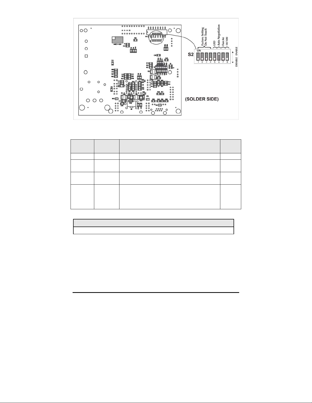
The table below shows the DIP Switch settings for McPC 10/100:
Feature Switch # Function Defaul
t
LFD 5 Link Fault Detection (Available in Force modes only) OFF
AN 6
Force 7
10/100 8
Auto Negotiation Mode (Valid only when Force
mode is disabled)
Force Mode – Forces the converter to operate at 10
or 100 Mbps as determined by switch
Valid only when switch
When ON, the converter operates at 10 Mbps.
When
is only valid in Force Mode, i.e. when switch
8
7
is
ON.
OFF
, the converter operates at 100 Mpbs. 8
7
is ON
ON
OFF
OFF
NOTE
Switch #'s
1 – 4
are factory configured
– DO NOT CHANGE
3
Page 7
Modes of Operation (PCI Version)
The McPC 10/100 features three modes of operation:
(AN)
,
Force-10 mode
and
Force-100 mode
. Configure the McPC 10/100 for
Auto Negotiation mode
one of these modes (factory default is Auto Negotiation mode). Refer to the Link
Fault Detection section for information on Link Fault Detection (LFD).
NOTE
The McPC 10/100 cannot be manually set for Half- or Full-Duplex. Duplex is
determined by the devices to which the McPC 10/100 is connected.
Auto Negotiation mode
is the mode most ideally suited for the McPC 10/100.
In this mode, the converter will optimally and automatically configure for speed
(10 or 100 Mbps) depending on the capabilities of the end stations.
To enable Auto Negotiation mode, set switch
7
and 8 in the
OFF
position.
6
to the ON position, with switches
Auto Negotiation Mode
In
Force 10 mode
, theMcPC10/100 acts as a 10Base-T to 10Base-FL media
converter; 100 Mbps signals are not accepted.
To enable
the
Force 10 mode
OFF
position.
, set switch 7 and 8 to the ON position, with switch 6 in
Force 10 Mode
In
Force 100 mode
, the McPC 10/100 acts as a 100Base-TX to 100Base-SX multimode or 100Base-FX single-mode fiber media converter; 10 Mbps signals are not
accepted.
To enable
8
in the
Force 100 mode
OFF
position.
, set switch 7 to the ON position, with switches 6 and
4
Page 8

Force 100 Mode
There is no Auto Negotiation in either of the Force modes.
Auto Negotiation (PCI Version)
When connecting two McPC 10/100s between two end stations (devices such as
switches, hubs and repeaters), all devices in the media conversion should ideally
support, and be utilizing, Auto Negotiation functionality. While it is possible to
have Auto Negotiating devices on one side of the media conversion and fixed
(non-Auto Negotiating) devices on the other, link LEDs will react differently
depending on where a link fault occurs. Therefore, IMC recommends:
Configuring every device in the media conversion for Auto Negotiation.
For installations where Auto Negotiation is NOT possible from one end of
the media conversion to the other, manually configure all devices for 10
Mbps or 100 Mbps connections.
Transparency (PCI Version)
Transparency is only available when using Auto Negotiation mode; it is not
available in either of the two Force modes. When the McPC 10/100 is Auto
Negotiating, Transparency treats the connection between the two end devices as
if there were no media converters installed. For example, in a typical application
where two media converters are installed between two copper-based switches,
the twisted pair cables as well as the fiber cable are seen as a single entity.
Therefore, if a fault occurs on any segment between the two end devices, link
LEDs on the end devices will extinguish.
Transparency is available when the McPC 10/100 is operating in Auto Negotiation
mode. Therefore
must be
OFF
6
(AN) must be ON and 5 (LFD), 7 (Force) and 8 (10 or 100)
.
Transparency
5
Page 9

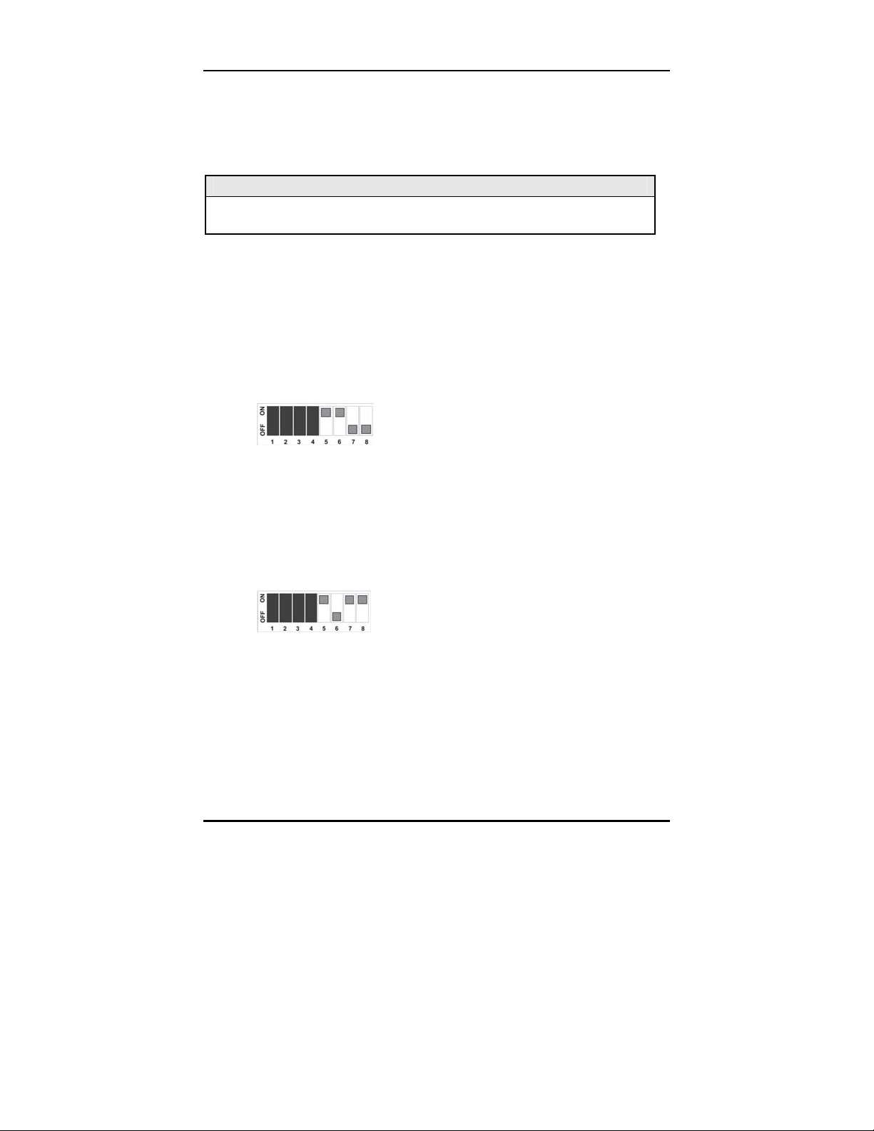
Link Fault Detection (PCI Version)
Link Fault Detection (LFD) is only available when using Force 10 or Force 100
mode. It is not available in Auto Negotiation mode. When LFD is enabled and the
input link is down at one interface to the McPC 10/100, the transmitter output on
that interface will blink. It applies to both network interfaces and to both data
rates. If the link at the other interface to the McPC 10/100 is also down, there is
no output. LFD causes the Link Up indicator of the link partner to blink.
When the McPC 10/100 is in one of the Force modes, enable LFD by setting
the ON position. Disable LFD by resetting 5 to its default,
OFF
, position. In order
for LFD to function properly, Force mode must be enabled by setting
with either
8 ON
for 10 Mbps or 8
OFF
for100 Mbps.
7
to ON
5
to
NOTE
6
must also be ON when enabling LFD.
LFD On Positions for 10 Mbps
LFD On Positions for 100 Mbps
NOTE
When using the LFD feature, if the DIP Switches are in any other combination
than listed above, the module may exhibit erratic behavior.
Twisted Pair Crossover/Pass-Through Button (PCI Version)
The McPC 10/100 features a crossover/pass-through button, located on the
faceplate next to the RJ-45 connector, to set the twisted pair connection type.
Select a pass-through connection by pressing the button. A crossover
connection is selected when the button is
OUT
. If it is not known which
connection is needed, set the button to whatever setting makes the twisted pair
LNK (link) LED glow.
6
Page 10

Crossover/Pass-Through Switch
7
Page 11

LED Indicators (PCI Version)
The McPC 10/100 features four diagnostic LEDs. The following are the LED
functions on the twisted pair port:
FX Activity LED Auto Negotiation LED
FX Link LED Power LED
FX 100 Mbps Active LED Link Fault Detection LED TX Link
TX 100 Mbps Activity LED TX Activity Crossover/ Pass Through Switch
Twisted Pair Port
P
AN
LFD
100
Green when the unit has power
Green when Auto Negotiation mode is enabled
Green when Link Fault Detection is enabled
Yellow when a 100 Mbps connection is detected
NOTE
This feature is only available when either
enabled. For more on this feature, see the LFD LED Activity section, below.)
Force 10
or
Force 100
mode is
Fiber Port
LNK
ACT
100
Green when a twisted pair link is established
Yellow when activity is detected on the port
Yellow when a 100 Mbps connection is detected
Link Fault Detection LED Activity (PCI Version)
When LFD is enabled and a fault occurs on a segment of the media conversion,
the various Link LEDs in that conversion will either blink or extinguish. LEDs may
react differently depending on the type of end devices in the conversion, whether
the McPC 10/100 is in
Force 10
or
Force 100
mode, where the fault occurs, etc.
For questions, please contact Technical Support.
NOTE
Twisted pair AND fiber optic cables must be connected, and the twisted pair
crossover/pass-through switch set correctly, before either LNK LED will glow
solid.
8
Page 12

9
10
Page 13

ISA Version
Installing the McPC 10/100 (ISA Version)
Offering plug-and-play operation, the McPC 10/100 comes ready to install,
utilizing power from the PC’s power supply. To install the McPC 10/100:
11.
Turn off the PC
12.
Remove its cover
13.
Find an empty ISA slot
Align the McPC 10/100 in the slot
14.
15.
Screw the the McPC 10/100 into the computer casing’s bracket
16.
Make sure the McPC 10/100 does not extend past the edge of the case
Attach the keyed mini-power connector to the McPC 10/100
17.
18.
Attach the male end of the “Y” connector to one of the computer’s standard
size power connectors
Replace the cover
19.
20.
Attach the cables between the McPC 10/100 and the devices that will be
interconnected
NOTE
The McPC 10/100 DOES NOT plug into the motherboard. McPC 10/100 draws
power from the computer; no additional power source is necessary.
Page 14

Configuring the McPC 10/100 (ISA Version)
Before installing, configure McPC 10/100 for desired features using the DIP
Switch located as shown below on the printed circuit board (PCB). The following
illustration shows the location of the DIP Switch as well as its default settings.
Consult the chart below for the function of each switch.
The table below shows the DIP Switch settings for McPC 10/100:
Feature Switch # Function Defaul
t
LFD
AN
Force
10/100
5 Link Fault Detection (Available in Force modes only) OFF
6
7
8
Auto Negotiation Mode (Valid only when Force
mode is disabled)
Force Mode – Forces the converter to operate at 10
or 100 Mbps as determined by switch 8
7
is
Valid only when switch
When ON, the converter operates at 10 Mbps.
OFF
When
is only valid in Force Mode, i.e. when switch
, the converter operates at 100 Mpbs. 8
ON.
7
is ON
ON
OFF
OFF
Switch #'s
1 – 4
are factory configured
NOTE
11
– DO NOT CHANGE
Page 15

Modes of Operation (ISA Version)
The McPC 10/100 features three modes of operation:
Force-10 mode
and
Force-100 mode
. Configure the McPC 10/100 for one of
Auto Negotiation mode
these modes (factory default is Auto Negotiation mode). Refer to the Link Fault
Detection section for information on Link Fault Detection.
NOTE
The McPC 10/100 cannot be manually set for Half- or Full-Duplex. Duplex is
determined by the devices to which the McPC 10/100 is connected.
Auto Negotiation mode
is the mode most ideally suited for the McPC 10/100.
In this mode, the converter will optimally and automatically configure for speed
(10 or 100 Mbps) depending on the capabilities of the end stations.
To enable Auto Negotiation mode, set switch
7
and 8 in the
OFF
position.
6
to the ON position, with switches
Auto Negotiation Mode
Force 10 mode
In
, theMcPC10/100 acts as a 10Base-T to 10Base-FL media
converter; 100 Mbps signals are not accepted.
To enable
the
Force 10 mode
OFF
position.
, set switch 7 and 8 to the ON position, with switch 6 in
Force 10 Mode
,
Force 100 mode
In
, the McPC 10/100 acts as a 100Base-TX to 100Base-SX multimode or 100Base-FX single-mode fiber media converter; 10 Mbps signals are not
accepted.
To enable
8
in the
Force 100 mode
OFF
position.
, set switch 7 to the ON position, with switches 6 and
12
Page 16

Force 100 Mode
There is no Auto Negotiation in either of the Force modes.
Auto Negotiation (ISA Version)
When connecting two McPC 10/100s between two end stations (devices such as
switches, hubs and repeaters), all devices in the media conversion should ideally
support, and be utilizing, Auto Negotiation functionality. While it is possible to
have Auto Negotiating devices on one side of the media conversion and fixed
(non-Auto Negotiating) devices on the other, link LEDs will react differently
depending on where a link fault occurs. Therefore, IMC recommends:
Configuring every device in the media conversion for Auto Negotiation.
For installations where Auto Negotiation is NOT possible from one end of
the media conversion to the other, manually configure all devices for 10
Mbps or 100 Mbps connections.
Transparency (ISA Version)
Transparency is only available when using Auto Negotiation mode; it is not
available in either of the two Force modes. When the McPC 10/100 is Auto
Negotiating, Transparency treats the connection between the two end devices as
if there were no media converters installed. For example, in a typical application
where two media converters are installed between two copper-based switches,
the twisted pair cables as well as the fiber cable are seen as a single entity.
Therefore, if a fault occurs on any segment between the two end devices, link
LEDs on the end devices will go out.
Transparency is available when the McPC 10/100 is operating in Auto Negotiation
mode. Therefore
or 100) must be
6
Auto Negotiation must be ON and 5 (LFD), 7 (Force) and 8 (10
OFF
.
Transparency
Link Fault Detection (ISA Version)
13
Page 17

Link Fault Detection (LFD) is only available when using Force 10 or Force 100
mode. It is not available in Auto Negotiation mode. When LFD is enabled and the
input link is down at one interface to the McPC 10/100, the transmitter output on
that interface will blink. It applies to both network interfaces and to both data
rates. If the link at the other interface to the McPC 10/100 is also down, there is
no output. LFD causes the Link Up indicator of the link partner to blink.
When the McPC 10/100 is in one of the Force modes, enable LFD by setting
ON
position. Disable LFD by resetting 5 to its default,
the
OFF
, position. In order
for LFD to function properly, Force mode must be enabled by setting
with either
8 ON
for 10 Mbps or 8
OFF
for100 Mbps. NOTE: 6 must also be ON
7
to ON
5
to
when enabling LFD.
LFD On Positions for 10 Mbps
LFD On Positions for 100 Mbps
NOTE
When using the LFD feature, if the DIP Switches are in any other combination
than listed above, the module may exhibit erratic behavior.
Twisted Pair Crossover/Pass-Through Button (ISA Version)
The McPC 10/100 features a crossover/pass-through button, located on the
faceplate next to the RJ-45 connector, to set the twisted pair connection type.
Select a pass-through connection by pressing the button. A crossover
connection is selected when the button is
OUT
. If it is not known which
connection is needed, set the button to whatever setting makes the twisted pair
LNK (link) LED glow.
14
Page 18

Crossover/Pass-Through Switch
15
Page 19

LED Indicators (ISA Version)
The McPC 10/100 features four diagnostic LEDs. The following are the LED
functions on the twisted pair port:
Crossover/Pass- TX Link TX 100 Mbps Activity LED
Through Switch TX Activity Link Fault Detection LED FX 100 Mbps
Active LED
Power Link LED FX Link LED
Auto Negotiation Activity LED FX Activity
Twisted Pair Port
P
AN
LFD
100
Green when the unit has power
Green when Auto Negotiation mode is enabled
Green when Link Fault Detection is enabled
Yellow when a 100 Mbps connection is detected
NOTE
This feature is only available when either
Force 10
or
Force 100
mode is
enabled. For more on this feature, see the Link Fault Detection LED Activity
section, below.
Fiber Port
LNK
ACT
100
Green when a twisted pair link is established
Yellow when activity is detected on the port
Yellow when a 100 Mbps connection is detected
Link Fault Detection LED Activity (ISA Version)
When LFD is enabled and a fault occurs on a segment of the media conversion,
the various Link LEDs in that conversion will either blink or extinguish. LEDs may
react differently depending on the type of end devices in the conversion, whether
the McPC 10/100 is in
Force 10
or
Force 100
mode, where the fault occurs, etc.
For questions, please contact Technical Support.
16
Page 20

NOTE
Twisted pair AND fiber optic cables must be connected, and the twisted pair
crossover/pass-through switch set correctly, before either LNK LED will glow
solid.
17
Page 21

Specifications (PCI and ISA Versions)
Environmental
Operating Temperature
32° - 104° F (0° - 40° C)
Storage Temperature
0° - 160° F (-20° - 71° C)
Humidity:
5 - 95% (non-condensing)
Current Draw:
0.7A @ 5VDC
Electrical
Input Load
5V
B&B Electronics Technical Support
Tel:
(800) 346-3119 (in the U.S. and Canada)
Monday-Friday, 7:00am-7”00pm CST
+353 91 792444 (Europe)
Monday through Friday 8:00am - 5:00pm GMT
Fax:
E-Mail:
Web:
(815) 433-5109
support@bb-elec.com
www.bb-elec.com
18
Page 22

Fiber Optic Cleaning Guidelines
Fiber Optic transmitters and receivers are extremely susceptible to contamination
by particles of dirt or dust, which can obstruct the optic path and cause
performance degradation. Good system performance requires clean optics and
connector ferrules.
Use fiber patch cords (or connectors, if you terminate your own fiber) only
1.
from a reputable supplier; low-quality components can cause many hard-todiagnose problems in an installation.
2.
Dust caps are installed at B&B Electronics to ensure factory-clean optical
devices. These protective caps should not be removed until the moment of
connecting the fiber cable to the device. Should it be necessary to
disconnect the fiber device, reinstall the protective dust caps.
Store spare caps in a dust-free environment such as a sealed plastic bag or
3.
box so that when reinstalled they do not introduce any contamination to the
optics.
4.
If you suspect that the optics have been contaminated, alternate between
blasting with clean, dry, compressed air and flushing with methanol to
remove particles of dirt.
19
Page 23

Safety Certifications
UL/CUL: Listed to Safety of Information Technology Equipment, including
Electrical Business Equipment.
CE: The products described herein comply with the Council Directive on
Electromagnetic Compatibility (2004/108/EC) and the Council
Directive on Electrical Equipment Designed for use within Certain
Voltage Limits (2006/95/EC). Certified to Safety of Information
Technology Equipment, Including Electrical Business Equipment.
For further details, contact B&B Electronics.
European Directive 2002/96/EC (WEEE) requires that any equipment that bears
this symbol on product or packaging must not be disposed of with unsorted
municipal waste. This symbol indicates that the equipment should be disposed
of separately from regular household waste. It is the consumer’s responsibility to
dispose of this and all equipment so marked through designated collection
facilities appointed by government or local authorities. Following these steps
through proper disposal and recycling will help prevent potential negative
consequences to the environment and human health. For more detailed
information about proper disposal, please contact local authorities, waste
disposal services, or the point of purchase for this equipment.
20
Page 24

International Headquarters
B&B Electronics
707 Dayton Road
Ottawa, IL 61350 USA
Phone (815) 433-5100 — General Fax (815) 433-5105
Website: www.bb-elec.com
European Headquarters
B&B Electronics
Westlink Commercial Park
Oranmore, Co. Galway, Ireland
Phone +353 91-792444 — Fax +353 91-79244S5
Website: www.bb-elec.com
© 2013 B&B Electronics. All rights reserved.
The information in this document is subject to change without notice. B&B Electronics assumes no responsibility for
any errors that may appear in this document. McPC 10/100 is a trademark of B&B Electronics. Other brands or
product names may be trademarks and are the property of their respective companies.
Document Number 55-80217-01 C0 September 2013
 Loading...