

Page 1
McBasic 10/100
Operation Manual
Page 2

FCC Radio Frequency Interference Statement
This equipment has been tested and found to comply with the limits for a Class A computing device, pursuant to Part 15 of the FCC
Rules. These limits are designed to provide reasonable protection against harmful interference when the equipment is operated in a
commercial environment. This equipment generates, uses and can radiate radio frequency e nergy and, if not ins talled and used in
accordance with the instruction m anual, may cause harmful interfere nce to radio communications. Operation of this equipment in a
residential area is likely to cause harmful interference in which the user will be required to correct the interference at his own expense.
Any changes or modifications not expressly approved by the manufacturer could void the user’s authority to operate the equipment.
The use of non-shielded I/O cables may not guarantee compliance with FCC RFI limits. This digital apparatus does not exceed the Class
A limits for radio noise emission from digital apparatus set out in the Radio Interference Regulation of the Canadian Department of
Communications.
Le présent appareil numérique n’émet pas de bruits radioélectriques dépassant les limites applicables aux appareils numériques de
classe A prescrites dans le Règlement sur le brouillage radioélectrique publié par le ministère des Communications du Canada.
LIMITED LIFETIME WARRANTY
Effective for products of B&B Electronics shipped on or after May 1, 2013, B&B Electronics warrants that each such
product shall be free from defects in material and workmanship for its lifetime. This limited lifetime warranty is
applicable solely to the original user and is not transferable.
This warranty is expressly conditioned upon proper storage, installation, connection, operation and maintenance of
products in accordance with their written specifications.
Pursuant to the warranty, within the warranty period, B&B Electronics, at its option will:
1. Replace the product with a functional equivalent;
2. Repair the product; or
3. Provide a partial refund of purchase price based on a depreciated value.
Products of other manufacturers sold by B&B Electronics are not subject to any warranty or indemnity offered by
B&B Electronics, but may be subject to the warranties of the other manufacturers.
Notwithstanding the foregoing, under no circumstances shall B&B Electronics have any warranty obligations or any
other liability for: (i) any defects resulting from wear and tear, accident, improper use by the buyer or use by any
third party except in accordance with the written instructions or advice of the B&B Electronics or the manufacturer of
the products, including without limitation surge and overvoltage conditions that exceed specified ratings, (ii) any
products which have been adjusted, modified or repaired by any party other than B&B Electronics or (iii) any
descriptions, illustrations, figures as to performance, drawings and particulars of weights and dimensions contained
in the B&B Electronics’ catalogs, price lists, marketing materials or elsewhere since they are merely intended to
represent a general idea of the products and do not form part of this price quote and do not constitute a warranty
of any kind, whether express or implied, as to any of the B&B Electronics’ products.
THE REPAIR OR REPLACEMENT OF THE DEFECTIVE ITEMS IN ACCORDANCE WITH THE EXPRESS WARRANTY SET
FORTH ABOVE IS B&B ELECTRONIC’ SOLE OBLIGATION UNDER THIS WARRANTY. THE WARRANTY CONTAINED IN
THIS SECTION SHALL EXTEND TO THE ORIGINAL USER ONLY, IS IN LIEU OF ANY AND ALL OTHER WARRANTIES,
EXPRESS OR IMPLIED, AND ALL SUCH WARRANTIES AND INDEMNITIES ARE EXPRESSLY DISCLAIMED, INCLUDING
WITHOUT LIMITATION (I) THE IMPLIED WARRANTIES OF FITNESS FOR A PARTICULAR PURPOSE AND OF
MERCHANTABILITY AND (II) ANY WARRANTY THAT THE PRODUCTS ARE DO NOT INFRINGE OR VIOLATE THE
INTELLECTUAL PROPERTY RIGHTS OF ANY THIRD PARTY. IN NO EVENT SHALL B&B ELECTRONICS BE LIABLE FOR
LOSS OF BUSINESS, LOSS OF USE OR OF DATA INTERRUPTION OF BUSINESS, LOST PROFITS OR GOODWILL OR
OTHER SPECIAL, INCIDENTAL, EXEMPLARY OR CONSEQUENTIAL DAMAGES. B&B ELECTRONIC SHALL DISREGARD
AND NOT BE BOUND BY ANY REPRESENTATIONS, WARRANTIES OR INDEMNITIES MADE BY ANY OTHER PERSON,
INCLUDING WITHOUT LIMITATION EMPLOYEES, DISTRIBUTORS, RESELLERS OR DEALERS OF B&B ELECTRONIC
WHICH ARE INCONSISTENT WITH THE WARRANTY, SET FORTH ABOVE.
ii
Page 3

Table of Contents
FCC Radio Frequency Interference Statement .............................................................. ii
Limited Lifetime Warranty ........................................
About the McBasic 10/100 Module .................................................................................. 1
Installing the McBasic 10/100 ............................................................................................. 2
Configuring the McBasic 10/100 ....................................................................................... 3
Twisted Pair Crossover/Pass-Through Switch ............................................................... 3
Modes of Operation ............................................................................................................... 4
Troubleshooting Features .................................................................................................... 5
Link Fault Detection in Force Modes (LFD) .................................................................... 6
Operation ................................................................................................................................... 7
Installation Troubleshooting ............................................................................................... 8
Electrostatic Discharge Precautions .................................................................................. 9
Fiber Optic Cleaning Guidelines ..................................................................................... 10
B&B Electronics Technical Support ................................................................................ 11
Specifications ......................................................................................................................... 11
Safety Certifications ............................................................................................................. 12
Error! Bookmark not defined.
iii
Page 4
About the McBasic 10/100 Module
The McBasic 10/100 module is a low-cost, standalone, IEEE 802.3 singleconversion media converter which converts between:
10Base-T twisted pair and 10Base-FL multi-mode or single-mode fiber
100Base-TX twisted pair and 100Base-SX multi-mode fiber or 100Base-FX
single-mode fiber
The McBasic 10/100 is a 1U high, standalone unit that includes diagnostic LEDs
for each port and an internal, universal (100/240 VAC) power supply.
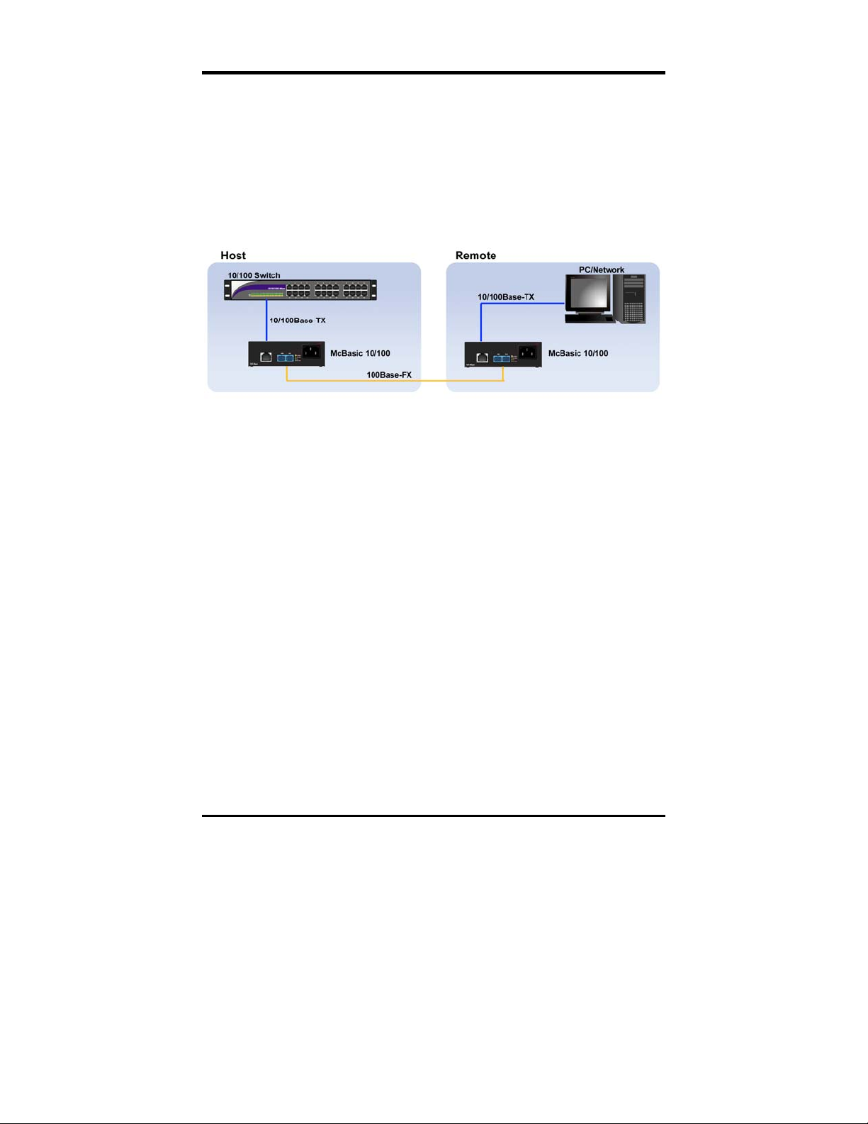
In many networks, the media converter is typically installed as a pair, between
two copper-based end devices. The McBasic 10/100 can also be installed as a
single media converter, between one copper-based device and the other a fiberbased device. However, when connected to certain fiber-based devices, there
may be difficulty in the installation: if a link partner that is connected to the
McBasic media converter is powered down on the copper port, noise on the
copper segment may be detected and transferred to the fiber line. A result of
the noise will generate errors that look like CRC errors. Some fiber-based devices
many detect this noise and disable the fiber segment.
1
Page 5

Installing the McBasic 10/100
The McBasic 10/100 comes ready to install. The only adjustments that may need
to be made after installation are:
Configuring the mode of operation and other features on the unit.
Setting the twisted pair port for a crossover workstation or pass-through
connection.
To install McBasic 10/100:
1. First make sure the unit is placed on a suitable flat surface, leaving some
space at the back of the unit.
Attach the cables between the McBasic 10/100 and each device that will be
2.
interconnected.
Plug the unit into a reliable, filtered power source.
3.
NOTE
All network cables must be connected before the link LEDs will glow.
2
Page 6
Configuring the McBasic 10/100
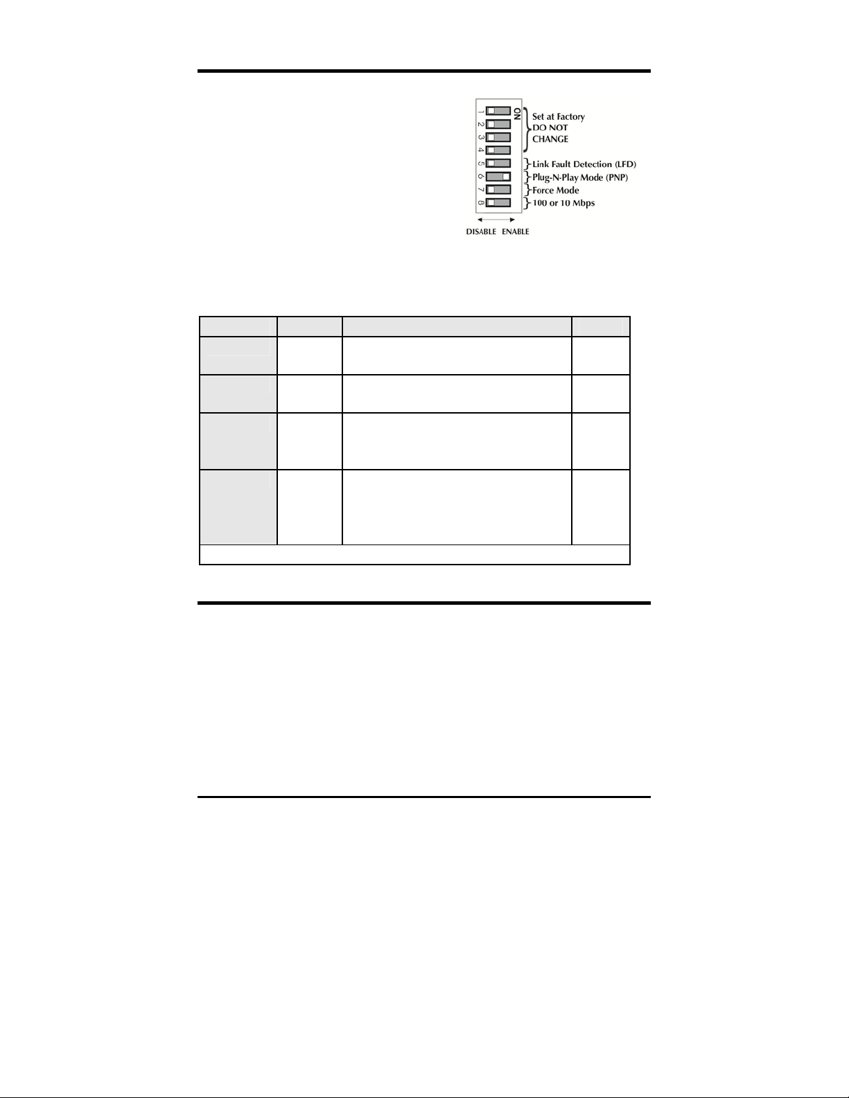
The McBasic 10/100 features an 8-position
DIP Switch for configuring the unit. This
switch is accessed through a cut-out in the
bottom of the unit. After configuring the
switch, power down the unit and then power
up again for the DIP Switch changes to take
effect.
The following table provides simplified definitions of the function of each switch.
Refer to the following sections for more detail.
Feature Switch Function Default
LFD S5 Link fault detection available in force
OFF
mode only (S7 is ON)
PNP (AN) S6 Plug-N-Play available when force
ON
mode is disabled (S7 is OFF)
Force S7 Force mode forces the module to
OFF
operate at 10 or 100 Mbps as
determined by S8
10/100 S8 When ON, operates at 10 Mbps.
OFF
When OFF, operates at 100 Mbps.
Available when force mode is enabled
(S7 is ON)
DIP Switches S1-S4 are factory configured—DO NOT CHANGE
Twisted Pair Crossover/Pass-Through Switch
The McBasic 10/100 has a Crossover/Pass-Through push-button switch, located
on the faceplate next to the RJ-45 connector, for setting the twisted pair
connection type.
Select a Pass-Through connection by pressing the push-button IN. A Crossover
connection is selected when the push-button is OUT. If not sure which
connection is needed, set the push-button to whatever setting makes the twisted
pair LNK (link) LED glow.
3
Page 7

Modes of Operation
The McBasic 10/100 has four modes of operation:
Auto Negotiation/PNP
FORCE 10Mbps
FORCE 100Mbps
Selective Advertising AN (All OFF)
NOTE
The McBasic 10/100 cannot be set for Half- or Full-Duplex manually. Duplex is determined
by the link partners connected to the McBasic 10/100.
The McBasic 10/100 media converter is typically installed in pairs and provides
compatibility with legacy 10BASE-FL devices, while also providing support for
100Mbps devices. This is a PHY based device to allow very low propagation
delays but in turn the speed and duplex of both its copper and fiber ports must
be the same. For the McBasic to function properly, the copper port must have
link before the fiber port will link up.
In a back to back configuration, both units must have the Plug-N-Play (PNP)
switch set to ON for the copper ports to auto negotiate from end to end. In this
mode the fiber link becomes transparent allowing the units at both ends of the
link to function as if they were connected over one copper line. All auto
negotiation signaling is the result of signaling received on the ports of the unit.
Only use this mode with two McBasic media converters installed in pairs, back to
back.
With all switches set to OFF
,
the unit sends its own Auto Negotiation (AN)
signaling on the copper port. This advertises both FDX and HDX with the
physical speed that is detected on the fiber line. This signaling cannot occur until
this fiber port is active. If auto negotiation signaling is also received over the
fiber from the far end equipment, the auto negotiation signaling on the copper
port will include this information.
In all of the FORCE modes, no auto negotiation signals are sent or acted on. The
unit will blindly send the speed assigned and supports either FDX or HDX data.
The LFD function is only available in the FORCE modes.
4
Page 8

Selective Advertising is a mode in which the speed and duplex for the copper and
the fiber are specifically advertised. This mode is available when DSW 5-8 are set
to OFF.
Switch Selective
Advertising
PNP
(AN)
Force
100
Force
10
Force
100 LFD
Force
10 LFD
LFD OFF OFF OFF OFF ON ON
PNP OFF ON OFF OFF OFF OFF
FORCE OFF OFF ON ON ON ON
10/100 OFF OFF OFF ON OFF ON
Troubleshooting Features
The McBasic 10/100 media converters include two advanced troubleshooting
features to help locate “silent failures” on the network.
Transparency
Link Fault Detection (LFD)
Transparency
Transparency is only available in PNP mode. Transparency treats the connection
between the two end devices as if there were no media converters installed. In a
typical application where two media converters are installed between two
copper-based switches, the twisted pair cables as well as the fiber cable are seen
as one entity. If a fault occurs on any segment between the two end devices, link
LEDs on the end devices will go out. This prevents any failure on the link
between the end units from going undetected.
As stated, transparency is available when McBasic 10/100 is operating in Auto
Negotiation mode:
S6 PNP (AN) must be ON
S5 (LFD), S7 (Force) and S8 (10 or 100) must be OFF
5
Page 9

Link Fault Detection in FORCE Modes (LFD)
Link Fault Detection (LFD) is only available when using Force 10 or Force 100
mode and provides the same information as link fault pass through as does in
PNP mode to detect silent failures. When LFD is enabled and the input link is
down at one interface to the McBasic 10/100, the transmitter output on that
interface is turned off for about 425ms every 3.8 seconds (i.e., blinking). It applies
to both network interfaces and to both data rates. If the link at the other
interface to the McBasic 10/100 is also down, there is no output. LFD causes the
Link Up indicator of the link partner to blink.
When the McBasic 10/100 is in one of the FORCE modes, enable LFD by setting
S5 to the ON position. Disable LFD by setting S5 to the OFF position.
In order for LFD to function properly, Force mode must be enabled by setting:
S7 to ON with either S8 ON for 10 Mbps or S8 OFF for 100 Mbps
S6 must also be ON
NOTE
When using the LFD feature, if the DIP Switches are in any other combination than listed
above, the McBasic 10/100 may exhibit erratic behavior.
Crossover/
Pass-through
Switch
Twisted Pair
LEDs
Fiber
LEDs
6
Page 10

Operation
The McBasic 10/100 features several diagnostic LEDs per port (see illustration
above). The LED functions for the McBasic 10/100 are:
Port LED Definition
LNK
Glows green when a twisted pair link is established.
ACT Glows yellow when data is detected on the port.
100
Glows yellow when 100 Mbps data is detected on
the port.
Twisted
Pair port
LFD Glows green when Link Fault Detection is enabled.
This feature is available only when force 10 or force
100 is enabled.
PNP (AN) Glows green when Auto Negotiation mode is
enabled.
PWR Glows green when unit has power.
100 Glows yellow when 100 Mbps data is detected on
Fiber port
ACT Glows green when data is detected on the port.
the port.
LNK Glows green when a fiber link is established.
NOTE
Before either LNK LED will glow solid, the twisted pair and fiber optic cables must be
connected and the twisted pair crossover/ pass-through switch set correctly.
7
Page 11

Installation Troubleshooting
During installation, first test the fiber and twisted pair connections with all
troubleshooting features disabled, then enable these features (if desired) just
before final installation. This will reduce the features’ interference with testing.
When working with units where the features cannot be disabled, both the twisted
pair and fiber connections must be established before the link LEDs will light.
To perform a physical loopback test on the Media Converter, have an appropriate
fiber patch cable, and then follow the four easy steps to test:
Step 1
Step 2
Configure the McBasic 10/100 to Force 100 Mbps mode.
Connect the media converter to the twisted pair device with a twisted
pair cable.
Step 3
Loop a single strand of fiber from the transmit port to the receive port
of the media converter.
Step 4
Verify that both the twisted pair and fiber links on the converter. Refer
to the LED Operation section.
NOTE
Use caution when conducting a loopback test. It is possible to create a network loop if
connecting the media converter’s twisted pair port to an active network. B&B Electronics
recommends connecting the twisted pair cable to a computer when performing this type of
test.
8
Page 12

Electrostatic Discharge Precautions
Electrostatic discharge (ESD) can cause damage to any product, add-in modules
or stand alone units, containing electronic components. Always observe the
following precautions when installing or handling these kinds of products
Do not remove unit from its protective packaging until ready to install.
1.
2.
Wear an ESD wrist grounding strap before handling any module or
component. If the wrist strap is not available, maintain grounded contact
with the system unit throughout any procedure requiring ESD protection.
3.
Hold the units by the edges; do not touch the electronic components or gold
connectors.
After removal, always place the boards on a grounded, static-free surface,
4.
ESD pad or in a proper ESD bag. Do not slide the modules or stand alone
units over any surface.
WARNING!
Integrated circuits and fiber optic components are
extremely susceptible to electrostatic discharge damage. Do not
handle these components directly unless you are a qualified
service technician and use tools and techniques that conform to
accepted industry practices.
9
Page 13

Fiber Optic Cleaning Guidelines
Fiber Optic transmitters and receivers are extremely susceptible to contamination
by particles of dirt or dust, which can obstruct the optic path and cause
performance degradation. Good system performance requires clean optics and
connector ferrules.
Use fiber patch cords (or connectors, if you terminate your own fiber) only
1.
from a reputable supplier; low-quality components can cause many hard-todiagnose problems in an installation.
2.
Dust caps are installed at B&B Electronics to ensure factory-clean optical
devices. These protective caps should not be removed until the moment of
connecting the fiber cable to the device. Should it be necessary to
disconnect the fiber device, reinstall the protective dust caps.
Store spare caps in a dust-free environment such as a sealed plastic bag or
3.
box so that when reinstalled they do not introduce any contamination to the
optics.
4.
If you suspect that the optics have been contaminated, alternate between
blasting with clean, dry, compressed air and flushing with methanol to
remove particles of dirt.
10
Page 14

B&B Electronics Technical Support
Tel:
(800) 346-3119 (in the U.S. and Canada)
Monday-Friday, 7:00am-7”00pm CST
+353 91 792444 (Europe)
Monday through Friday 8:00am - 5:00pm GMT
Fax:
E-Mail:
Web:
(815) 433-5109
support@bb-elec.com
www.bb-elec.com
Specifications
Environmental
Operating Temperature
+32°F to +122°F (0°C to +50°C)
Storage Temperature
-4°F to +158°F (-20°C to +70°C)
Humidity
5 to 95% (non-condensing)
Input Specifications
100-240 ±10% VAC, 50/60Hz, 1-0.5A
Fiber Optic Specifications
For fiber optic specifications, visit the B&B Electronics Web site at
http://www.imcnetworks.com/adocs/fcs.asp
11
Page 15

Safety Certifications
UL/CUL: Listed to Safety of Information Technology Equipment, including
Electrical Business Equipment.
CE: The products described herein comply with the Council Directive on
Electromagnetic Compatibility (2004/108/EC) and the Council
Directive on Electrical Equipment Designed for use within Certain
Voltage Limits (2006/95/EC). Certified to Safety of Information
Technology Equipment, Including Electrical Business Equipment.
For further details, contact B&B Electronics.
Class 1 Laser product, Luokan 1 Laserlaite,
Laser Klasse 1, Appareil A’Laser de Classe 1
European Directive 2002/96/EC (WEEE) requires that any equipment that bears
this symbol on product or packaging must not be disposed of with unsorted
municipal waste. This symbol indicates that the equipment should be disposed
of separately from regular household waste. It is the consumer’s responsibility to
dispose of this and all equipment so marked through designated collection
facilities appointed by government or local authorities. Following these steps
through proper disposal and recycling will help prevent potential negative
consequences to the environment and human health. For more detailed
information about proper disposal, please contact local authorities, waste
disposal services, or the point of purchase for this equipment.
12
Page 16

13
Page 17

International Headquarters
B&B Electronics
707 Dayton Road
Ottawa, IL 61350 USA
Phone (815) 433-5100 — General Fax (815) 433-5105
Website: www.bb-elec.com
European Headquarters
B&B Electronics
Westlink Commercial Park
Oranmore, Co. Galway, Ireland
Phone +353 91-792444 — Fax +353 91-79244S5
Website: www.bb-elec.com
© 2013 B&B Electronics. All rights reserved.
The information in this document is subject to change without notice. B&B Electronics assumes no responsibility for
any errors that may appear in this document. McBasic 10/100 is a trademark of B&B Electronics. Other brands or
product names may be trademarks and are the property of their respective companies.
Document Number 55-80216-01 B9 August 2013
 Loading...