

Page 1

iMediaChassis/3
Operation Manual
Page 2

FCC Radio Frequency Interference Statement
This equipment has been tested and found to comply with the limits for a Class B computing device, pursuant to Part 15 of the FCC Rules.
These limits are designed to provide reasonable protection against harmful interference when the equipment is operated in a commercial
environment. This equipment generates, uses and can radiate radio frequency energy and, if not installed and used in accordance with the
instruction manual, may cause harmful interference to radio communications. Operation of this equipment in a residential area is likely to
cause harmful interference in which the user will be required to correct the interference at his own expense.
Any changes or modifications not expressly approved by the manufacturer could void the user’s authority to operate the equipment.
The use of non-shielded I/O cables may not guarantee compliance with FCC RFI limits. This digital apparatus does not exceed the Class B
limits for radio noise emission from digital apparatus set out in the Radio Interference Regulation of the Canadian Department of
Communications.
Le présent appareil numérique n’émet pas de bruits radioélectriques dépassant les limites applicables aux appareils numériques de classe B
prescrites dans le Règlement sur le brouillage radioélectrique publié par le ministère des Communications du Canada.
Warranty
IMC Networks warrants to the original end-user purchaser that this product, EXCLUSIVE OF SOFTWARE, shall be free
from defects in materials and workmanship under normal and proper use in accordance with IMC Networks' instructions
and directions for a period of six (6) years after the original date of purchase. This warranty is subject to the limitations set
forth below.
At its option, IMC Networks will repair or replace at no charge the product which proves to be defective within such
warranty period. This limited warranty shall not apply if the IMC Networks product has been damaged by unreasonable
use, accident, negligence, service or modification by anyone other than an authorized IMC Networks Service Technician
or by any other causes unrelated to defective materials or workmanship. Any replaced or repaired products or parts carry
a ninety (90) day warranty or the remainder of the initial warranty period, whichever is longer.
To receive in-warranty service, the defective product must be received at IMC Networks no later than the end of the
warranty period. The product must be accompanied by proof of purchase, satisfactory to IMC Networks, denoting
product serial number and purchase date, a written description of the defect and a Return Merchandise Authorization
(RMA) number issued by IMC Networks. No products will be accepted by IMC Networks which do not have an RMA
number. For an RMA number, contact IMC Networks at PHONE: (800) 624-1070 (in the U.S and Canada) or (949) 4653000 or FAX: (949) 465-3020. The end-user shall return the defective product to IMC Networks, freight, customs and
handling charges prepaid. End-user agrees to accept all liability for loss of or damages to the returned product during
shipment. IMC Networks shall repair or replace the returned product, at its option, and return the repaired or new
product to the end-user, freight prepaid, via method to be determined by IMC Networks. IMC Networks shall not be
liable for any costs of procurement of substitute goods, loss of profits, or any incidental, consequential, and/or special
damages of any kind resulting from a breach of any applicable express or implied warranty, breach of any obligation
arising from breach of warranty, or otherwise with respect to the manufacture and sale of any IMC Networks product,
whether or not IMC Networks has been advised of the possibility of such loss or damage.
EXCEPT FOR THE EXPRESS WARRANTY SET FORTH ABOVE, IMC NETWORKS MAKES NO OTHER WARRANTIES,
WHETHER EXPRESS OR IMPLIED, WITH RESPECT TO THIS IMC NETWORKS PRODUCT, INCLUDING WITHOUT
LIMITATION ANY SOFTWARE ASSOCIATED OR INCLUDED. IMC NETWORKS SHALL DISREGARD AND NOT BE
BOUND BY ANY REPRESENTATIONS OR WARRANTIES MADE BY ANY OTHER PERSON, INCLUDING EMPLOYEES,
DISTRIBUTORS, RESELLERS OR DEALERS OF IMC NETWORKS, WHICH ARE
INCONSISTENT WITH THE WARRANTY SET FORTH ABOVE. ALL IMPLIED WARRANTIES INCLUDING THOSE OF
MERCHANTABILITY AND FITNESS FOR A PARTICULAR PURPOSE ARE HEREBY LIMITED TO THE DURATION OF THE
EXPRESS WARRANTY STATED ABOVE.
Every reasonable effort has been made to ensure that IMC Networks product manuals and promotional materials
accurately describe IMC Networks product specifications and capabilities at the time of publication. However, because of
ongoing improvements and updating of IMC Networks products, IMC Networks cannot guarantee the accuracy of printed
materials after the date of publication and disclaims liability for changes, errors or omissions.
ii
Page 3

Table of Contents
FCC Radio Frequency Interference Statement ...........................................................ii
Warranty................................................................................................................... ii
About the iMediaChassis/3 ........................................................................................4
Installing the iMediaChassis/3 ....................................................................................5
Installing Application Modules...................................................................................5
Installing Management Modules ................................................................................6
Connecting Chassis and Modules ..............................................................................7
Configuring an SNMP-Management Card..................................................................7
SNMP Write Lock .....................................................................................................7
Using Telnet..............................................................................................................9
About DHCP.............................................................................................................9
About iConfig..........................................................................................................10
About Serial Port Configuration ...............................................................................10
Before using iView² .................................................................................................15
Installing and Using iView² ......................................................................................15
Power Supply..........................................................................................................16
Temperature Control...............................................................................................17
Specifications ..........................................................................................................18
IMC Networks Technical Support............................................................................19
Safety Certifications.................................................................................................19
iii
Page 4
About the iMediaChassis/3
The iMediaChassis/3 is a modular chassis platform designed for use with the IMC
Networks SNMP-manageable series of modules (iMcV). The iMediaChassis/3 features
three slots for installing application series modules plus an additional slot for installing
an SNMP management module. The included SNMP Lock feature allows the
management slot to save SNMP settings while the management module is removed.
The iMediaChassis/3 can also hold two double wide “iMcV” modules, when there is
no SNMP management card in the management slot. Double-wide modules with
built-in management, such as the iMcV-Giga-FiberLinX-II, can be managed in the
chassis without the need for an SNMP module in the management slot.
The power supply configurations available for the iMediaChassis/3 include the
following:
•
Single AC
•
Single DC
•
AC and DC (available 2007)
•
AC and AC (available 2007)
•
DC and DC (available 2007)
This chassis is shipped with three of the slots covered by faceplates and one slot open
(slot 3).
4
Page 5

Installing the iMediaChassis/3
Before installing the application modules into an iMediaChassis/3, install the chassis
first. When installing the chassis, be sure to observe the following precautions to
prevent electrical or mechanical damage:
• Stay within the chassis power rating to prevent overload of supply circuits or
damage to overcurrent protection and supply wiring.
• Maintain reliable earth ground, especially when connecting to a power strip
instead of directly to a branch circuit.
• Protect the chassis from exposure to sunlight and electrical or magnetic fields.
Fault-Tolerant Power
The fault-tolerant powering option applies to units utilizing two power supplies. If
failure occurs on one power supply, the other supply takes over in its place and
carries the power load. Refer to the
Power Supply
and
Temperature Control
sections
for wiring, alarm, and Trap information.
NOTE
The iMediaChassis/3 power supply is not field replaceable.
Installing Application Modules
Refer to the module installation guide for configuration information. To install a
module, remove the faceplate (if present) covering the slot where the module will be
installed. Double-wide modules will occupy two slots. Slide the module into the
chassis using the card guides, and secure the module to the chassis by tightening the
captive screw. Each module slot provides 1.5 Amps. The management slot uses a
connector that is longer than slots 1-3 and should only be used for installing the
management module.
INSTALLATION TIP
The module hardware configuration that is set using dip switches, is overridden by the
chassis management when the module is installed in a managed chassis.
Use the management software to ensure that the module is properly configured.
5
Page 6

Installing Management Modules
t
Slot 1 Slot 2
Management Slo
Slot 3
An SNMP Management Module must be installed in the iMediaChassis/3 to enable
module and chassis management (except when using modules with built-in
management, such as the iMcV-Giga-FiberLinX-II). The SNMP Management module
installs in the management slot located at the bottom left of the chassis. This slot is
only for the management module; do not install application modules such as media
conversion and mode conversion modules in this slot. Double wide modules
installed in Slot 1 will overlap the management slot.
NOTE
The SNMP Management module includes DIP switches. These switches are
factory set and must not be moved.
SNMP Management Module LEDs
Each SNMP Management Module features several LEDs.
The LED functions are:
• LNK/ACT
Glows green when a link is established on port.
Blinks green when data activity occurs.
• FDX/COL:
Glows amber when port is in Full-Duplex mode.
Blinks amber when port is operating in Half-Duplex mode and
collisions occur.
• TEMP:
Glows amber when temperature of unit surpasses a user-defined
level.
• PS
Not used for the iMediaChassis/3.
• FAN A / FAN B
Not used for the iMediaChassis/3.
6
Page 7

Connecting Chassis and Modules
An iMediaChassis/3 with an installed management module connects to the LAN via
an external 10/100 twisted pair connection. Connect the chassis to the network by
plugging one end of a CAT-5 twisted pair cable into the port labeled
MGMT
on the
management card, or the management-enabled application card. Plug the other end
of the cable into a device (e.g., switch, hub, etc.) in an existing Ethernet network.
The port labeled
OPTION
is reserved for future use. Both twisted pair ports include
the AutoCross feature. This feature automatically enables either a crossover or a
straight-through connection, depending on the connected device.
Configuring an SNMP-Management Card
Once connected to the LAN, assign the iMediaChassis/3 IP configuration information
(e.g., IP address, subnet mask, etc.).
You can assign the IP information by using one of the following:
• iConfig
• The management module serial port
• DHCP (Dynamic Host Control Protocol); DHCP must be enabled through serial
configuration
You can also create community strings, assign access rights, configure Traps and
more. Using iConfig allows more Trap and MIB access configuration options than
when using the serial port.
After assigning the iMediaChassis/3 an IP address, use iView² or another SNMPcompatible Network Management System (NMS) to remotely configure, monitor and
manage the modules installed within the unit.
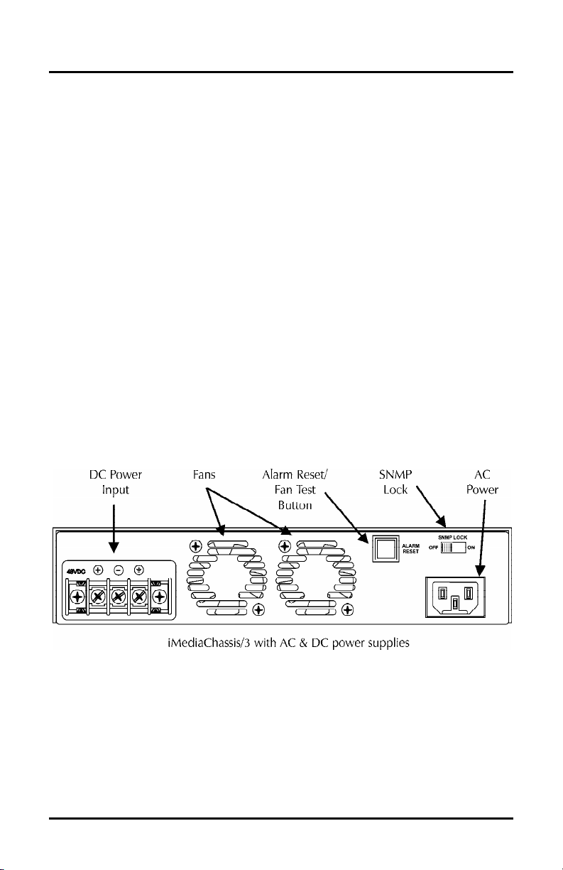
SNMP Write Lock
There is an SNMP Write Lock switch located on the back of
the iMediaChassis/3. The SNMP Write Lock switch prevents
a new management board from re-configuring the
application module settings (like the status of features such as
LinkLoss, FiberAlert, Force mode, etc.) made by SNMP and held on the previous
management board.
7
Page 8

The switch has two settings.
OFF
is the normal operating position and ON is the
locked position.
IMPORTANT USAGE INFORMATION
Leave the SNMP Write Lock switch in the
ONLY move the switch to the
ON
OFF
position during day-to-day operation.
position when changing the SNMP management
board.
The SNMP management module can be removed and replaced when necessary. A
saved firmware file can be uploaded to the second SNMP module to retain
configuration settings. Make sure that the SNMP Write Lock switch is set to the
ON
position. Save the firmware file periodically in case there is a need to replace the
SNMP management module (refer to the
About Serial Port Configuration
section for
more information).
When the management module is removed while the SNMP Write Lock switch is set
to
OFF
, the application module configurations revert to dip switch settings. Make
sure the dip switches are set to the same configuration as the SNMP management.
Re-installing the same management module will return the application modules to
the SNMP management configuration. Installing a new management module when
the switch is set to
OFF
will cause the installed application modules to use the
management settings of the new module. Make sure to always reconfigure
application modules when moving them from one chassis to another.
Using the SNMP Write Lock Switch
To lock the SNMP module settings by using the SNMP Lock Switch, perform the
following:
1.
Set the SNMP Write Lock switch to
2.
After configuring all application module settings by using SNMP, use iConfig to
OFF
.
make a backup copy of the SNMP management module firmware.
NOTE
These first two steps are typically performed during initial installation.
3. To replace the SNMP management module, first set the SNMP Write Lock
switch to
4.
Remove the old SNMP management module and replace it with another SNMP
ON
.
module.
5.
Access the SNMP management module using iConfig. Select the
tab and click on
6.
Update the new board with the firmware backup made in step 2.
List Tasks
. Highlight
Flashsav
and click the
Administration
Terminate
button.
8
Page 9

7. Reboot the SNMP management module with the
reboot
command to enable
changes.
8.
After rebooting, set the SNMP Write Lock switch back to
OFF
. The previously
made settings are now active.
NOTE
When an SNMP card is removed while the Write Lock switch is set to ON, the current
application module settings are retained.
Never power-cycle the chassis while the Write Lock switch is set to
ON
. This will
reset the SNMP card back to its original factory settings.
SNMP (iView
switch is set to
2
) communication with the chassis is disabled when the Write Lock
ON
.
Using Telnet
The iMediaChassis/3 supports Telnet for remote configuration. Assign the
iMediaChassis/3 an IP address before using a Telnet session (refer to the
Information section for more information
). All of the configurations that are available
Assigning IP
from the serial port are also available from Telnet. Use only one Telnet session at a
time. Do not use an RS-232 serial session and a Telnet session at the same time.
NOTE
A Telnet session uses the same password as the iConfig application.
About DHCP
There is a DHCP client in the iMediaChassis/3. By default, the DHCP client is
disabled. If a DHCP server is present on the network and DHCP is enabled, the
DHCP client will initiate a dialogue with the server during the boot up sequence.
The server will then issue an IP address to the iMediaChassis/3. Once the new IP
address is received, the iMediaChassis/3 will reboot so that the new IP address will
take effect. Refer to the
About Serial Port Configuration
for more information about
Enabling/Disabling DHCP. When there is no DHCP server on the network, use
iConfig or serial configuration to manually set the IP addresses.
When DHCP is enabled, the IP address (default 10.10.10.10 or user configured) is
saved. When DHCP is disabled, the saved IP address will be reinstated and the
device will reboot.
DHCP servers give out lease times: devices renew their leases based on the
administrator-specified time. If a device cannot renew its lease, and the lease
expires, the device will be given the IP address 10.10.10.10 and will reboot.
9
Page 10

About iConfig
iConfig is a configuration utility (part of iView²) that lets users quickly and easily
complete the first stages of SNMP configuration for SNMP-manageable devices.
iConfig can set the IP address, subnet mask and default gateway as well as define the
SNMP community strings and Traps.
In addition to the above functions, iConfig offers an authorized IP address system and
access restriction to MIB groups supported by manageable devices. These extra
layers of security are purely optional and do not affect SNMP compatibility in any
way.
The iConfig utility can also be used to upload new versions of the system software. It
also offers diagnostic capabilities for faster resolution of technical support issues.
The default user ID for both iConfig and Telnet is:
• User:
• Password:
admin
admin
The iConfig utility works with the Windows 98, Windows NT, Windows 2000, and
Windows XP operating systems.
The iConfig utility is available as a standalone application as well as built in to the
Windows version of iView² (Windows 98 users must use the standalone version of the
iConfig utility). Both applications are included on the iView² CD. Refer to the
iConfig utility online help file for more information about the iConfig utility.
About Serial Port Configuration
The SNMP management module used with the iMediaChassis/3 features a serial port
that includes an IBM-compatible DB-9 serial connector. To connect an
iMediaChassis/3 to a computer, use a straightthrough (pin-to-pin) cable. (When the computer
has a serial port using a connection not
compatible with a DB-9 COM port, use the pin
connection chart for reference in making a cable.)
Make sure the cable length is less than 50 ft.
(15.24 m). Plug one end of the cable into the
DB-9 connector on the iMediaChassis/3 and the
DB-9 Pin Connection Chart
Function Pin#
Transmit (Out) 2
Receive (In) 3
Ground 5
Reserved 1,4,6-9
other into the appropriate port on the computer.
Set the computer for VT-100 emulation. The serial port on the computer should be
set for: 38.4K baud, 8 data bits, 1 stop bit, no parity, no flow control.
10
Page 11

Main Serial/Telnet Configuration Screen
p
After running through an initial self-test, the screen will display the following message:
“<Press Enter> for Device Configuration.” Press
Enter
to display the main
configuration screen:
Saved Values. <These values will be active after reboot>
IP Address - 000.000.000.000
Subnet Mask - 000.000.000.000 DHCP is not active
Default Gateway - 000.000.000.000
Server IP Addr - 000.000.000.000
New Prom File -
Current Values. <These values are in use now>
IP Address - 000.000.000.000
Subnet Mask - 000.000.000.000
Default Gateway – 000.000.000.000
Server IP Addr - 000.000.000.000
New Prom File -
Community String: public Access: r/w
Press I to enter new saved parameter values. Press P to change Password.
Press T to enter new Trap Destination. Press K to remove ALL Trap Destinations.
Press C to enter new Community String. Press U to remove ALL Community Strings.
Press E to End session. Type REBOOT to reboot unit. Press D for DHCP On/Off.
Press S
Saved Values
aceBar for additional commands.
— displays changes made during current session.
promfilename
promfilename
• IP Address (MUST be assigned during initial configuration)
• Subnet Mask (MUST be assigned during initial configuration)
• Default Gateway
• Server IP Address
• Prom File Name
Current Values
— displays values currently in use.
• IP Address (IP address of SNMP agent)
• Subnet Mask (mask to define IP subnet to which agent is connected)
• Default Gateway (default router for IP traffic outside subnet)
• Server IP Address
• Prom File Name
Commands
• I
= Enter New Saved Parameter Values
• P
= Change Password
• T
= New Trap Destination
• K
= Remove ALL Trap Destinations
• C
= New Community String
• U
= Delete ALL Community Strings
• D
= Enable/Disable DHCP
• E
= End Session
• Space Bar
= Opens device specific configuration options (tasks, memory,
cleandb, download, version, reboot, sysname, accounts, and modules).
11
Page 12

NOTE
The F2 key functions as a Delete key on VT-100 terminal emulators.
Reboot after making any modifications to the Saved Values or changes will not take
effect. To reboot, type the word
reboot
at the prompt on the main configuration
screen, or cycle the power.
Never cycle the power with the SNMP Write Lock switch set to
ON
.
Assigning IP Information
To modify the Saved Parameter Values (i.e., assign IP address and subnet mask), press
I
. Enter the IP address and subnet mask for the connected device. Press
each. A Default Gateway may also be assigned (or press
Enter
to skip).
Enter
after
When finished, press
Enter
, then type
reboot
for changes to take effect. The Saved
Values and Current Values should now both display the changes made (e.g., new IP
address and subnet mask).
Creating Community Strings for SNMP
The purpose of community strings is to add a level of security to a network. The
default community string is named “public” and has read/write access. Delete the
“public” string and add necessary custom community strings such as one with readonly access (for general use), the other with read/write access (for the administrator).
To create a new community string, go to the main configuration screen and press
C
.
Enter the name of the new community (up to 16 characters, no spaces) and press
Enter
. Assign the community string’s access rights by typing one of the following:
• R = read-only access
• W = read/write access
• Enter = abort
Press
Enter
to create the Community String. When finished, press
reboot
for changes to take effect.
Enter
, then type
The Saved Values and Current Values should now both display the changes made
(e.g., new IP address and subnet mask).
Deleting Community Strings
To delete all community strings and start over, press U. Press Y to proceed, N to
abort when asked, “Are you sure you want to delete all future strings?” Then, press
Enter
.
This function will delete all community strings. Use iConfig to selectively delete
community strings.
12
Page 13

Assigning Trap Destinations
The manageable device sends Traps to a management PC when a certain event takes
place. To enter a Trap destination, press
device when asked to “Enter a New IP Address.” Then, press
T
. Type the IP address of the destination
Enter
. Type the name
of the community string (that the destination device has been configured to accept)
and press
Enter
. This function enables all of the device’s Traps. Use iConfig to
selectively activate and de-activate specific Traps.
Removing Trap Destinations
To remove all Trap destinations, press K. Press Y to confirm. Press N to abort. Then,
press
Enter
.
Password Protection on Serial Port
Password protect the serial configuration process by pressing P from the main
configuration screen. Enter a password. (Passwords are case sensitive.) Enter the
password (spaces are NOT allowed) and press
requested whenever logging on. To remove password protection, select
instead of entering a password press
Enter
Enter
. This password will be
P
and
.
It is the responsibility of the network administrator to store and maintain the
password lists. If passwords are lost, neither the end user nor IMC Networks can
retrieve them.
Enabling/Disabling DHCP
To Enable/Disable DHCP, press D. Then, type
reboot
for the changes to take effect.
Ending a Session
Be sure to press E before disconnecting the cable. This stops the device from sending
feedback status through to the serial port.
Device-Specific Options
Pressing the space bar from the Main Configuration screen opens the Device Specific
Commands screen:
Command Description
-------- ----------tasks Display Task List
memory Display Memory Usage
cleandb Reboot With Clean Database
download File Download
version Show Firmware Version
reboot Reboot Unit
sysname Change SysName
accounts Add or Delete Username/Password Accounts
modules Display Modules
->
Press RETURN To Go Back To Main Screen.
13
Page 14

Type the name of the action and press
Enter
• tasks
Displays the task list including the task priority.
.
• memory
Displays the memory usage.
• cleandb
Removes all information in the database except the IP address of device.
• download
Opens the firmware TFTP download screen.
• version
Displays the firmware version and build date.
• reboot
Reboots the unit.
• accounts
Allows management of Usernames/Passwords account. Administrators must
maintain a password list.
• modules
Displays a list of installed modules including slot location.
Downloading Files
The iMediaChassis/3 accepts firmware downloads from a central server by using TFTP
protocol. Use serial configuration or a Telnet session to perform this download.
Make sure the IP Address and the name of the file are correct in the Current Values
section of the Main Configuration screen. If this information is not correct, make the
appropriate changes. To download a file, press the
List section of the Main Configuration screen (serial configuration). Type
and press
Enter
to display the Download a File screen. This screen displays the IP
Address of the TFTP server and the name of the file. Press
Space Bar
Enter
from the Command
download
to start downloading
the file.
If the download is interrupted, do not reset the module or reboot the chassis. Close
the session, then open a new TFTP session.
14
Page 15

Before using iView²
iView² is a network management application designed for use on the IMC Networks
intelligent networking devices. It features a graphic user interface (GUI) and gives
network managers the ability to monitor and control products from a variety of
platforms. iView² can also function as a snap-in module for HP OpenView Network
Node Manager.
System Requirements
To run iView², the management PC must be equipped with the following:
• 29 MB free disk space, 64 MB RAM
• Windows: NT 4.0 Service Pack 5, 2000 Professional, or XP
• Microsoft SNMP Services Installed
• Microsoft IE 4.0 or Higher (not required as default browser)
• Microsoft IIS required for Web Server version
Java versions require the following:
• 25 MB free disk space, 64 MB RAM
• Any OS capable of running Java (Windows 98 or above, Solaris, LINUX)
• Java Runtime v 1.3
Strongly recommended:
• 128 MB RAM
• Pentium III 650Mhz or Faster
• 17” Monitor @ 1024 x 768 Resolution or higher
Installing and Using iView²
Please consult the iView² CD for installation information. The iView² help file
provides assistance in configuring/managing IMC Networks’ modules.
When Using iView² with HP OpenView
During the installation, the iView² application will ask if HP OpenView is installed on
the management PC. Click
Yes
to integrate the appropriate files. Once in
OpenView, select IMC Networks from the toolbar to view the IMC Networks devices.
15
Page 16

When Not Using iView²
When using an application other than iView² for management, integrate the SNMP
vendor files (a.k.a. MIBs) into the application. The SNMP agent uses the following
Enterprise-specific MIB file and standard MIBs, which can be found in the MIB
directory on the CD included with the iMediaChassis/3: MCIMCV2C.MIB Enterprisespecific information for the agent. For example, configuration information, port type
information, link status, etc.
Using the MCIMCV2C.MIB
Refer to the management software documentation for information on how MIB files
are integrated into the software.
Power Supply
The iMediaChassis/3 ships with one or two AC or DC power supplies, or one of each,
depending on the model.
DC Power Supply Wiring Instructions
The following image shows the wiring configuration for a Telco application of -48
VDC power supply for the iMediaChassis/3.
NOTE
Incorrect wiring will result in chassis malfunction.
The iMediaChassis/3 is compliant with Isolated Grounding Plane practices. The
POSITIVE and NEGATIVE terminals are isolated from chassis ground and must have a
ground reference at the power-sourcing equipment.
16
Page 17

Alarm Reset
This feature is available on the fault-tolerant (dual-power supply) model of the
iMediaChassis/3. When one power supply malfunctions, an alarm will sound. A red
alarm reset button, located next to the power connector on the right side of the
power supply, stops this alarm. The LEDs on the management module and the
iView² software both display power supply failures. If a power supply failure occurs,
return the iMediaChassis/3 to IMC Networks for repair or replacement.
Last Gasp Alarm
The iMediaChassis/3 includes the Last Gasp feature which sends a Trap when both
power supplies malfunction, when both power supplies are powered down, or when
the AC line fails.
Temperature Control
The iMediaChassis/3 includes temperature activated fans and an SNMP temperature
Trap to protect the chassis from overheating.
Temperature Triggered Fans
The iMediaChassis/3 includes temperature triggered fans. When the temperature of
the chassis reaches 40° C, the two fans are activated. You can test the fans operation
by holding the Alarm Reset button down for 4 to 5 seconds. The fans will activate
and then they will turn off when you release the button. If the fans do not activate,
contact IMC Networks.
Temperature SNMP Trap
The management module includes a heat sensor for monitoring the temperature of
the iMediaChassis/3. You can define a threshold for chassis temperature by using
SNMP (refer to the iView² online help for more information about assigning Traps).
When the temperature of the chassis rises above the specified level, the SNMP agent
sends a Trap to the administrator. There is also an LED indicator on the SNMP
Management Module for module temperature (refer to the
Module LEDs
section for more information).
17
SNMP Management
Page 18

Specifications
DC Input:
± 36 to 72 VDC maximum @ 50 watts
AC Input:
100 to 240 VAC +10% @ 50 watts
Operating Temperature:
32° to 122° F (0° to 50° C)
Storage Temperature:
0° to 160° F (-20° to 70° C)
Humidity:
5 to 90% (non-condensing); 0 to 10,000 ft. altitude
Heat Output:
171 BTUs
Shipping Weight:
5 lbs (2.3 kg)
Dimensions:
H=1.73” W=7.50” D=8.74” (4.4 x 19.0 x 22.0 cm)
18
Page 19

IMC Networks Technical Support
Telephone:
(949) 465-3000
Toll Free:
Europe:
FAX:
E-Mail:
Web Site:
Safety Certifications
UL/CUL: Listed to Safety of Information Technology Equipment, including
CE: The products described herein comply with the Council Directive on
European Directive 2002/96/EC (WEEE) requires that any equipment that bears this
symbol on product or packaging must not be disposed of with unsorted municipal
waste. This symbol indicates that the equipment should be disposed of separately
from regular household waste. It is the consumer’s responsibility to dispose of this
and all equipment so marked through designated collection facilities appointed by
government or local authorities. Following these steps through proper disposal and
recycling will help prevent potential negative consequences to the environment and
human health. For more detailed information about proper disposal, please contact
local authorities, waste disposal services, or the point of purchase for this equipment.
(800) 624-1070 (U.S.A. and Canada)
+32-16-550880
(949) 465-3020
techsupport@imcnetworks.com
www.imcnetworks.com
Electrical Business Equipment.
Electromagnetic Compatibility (89/336/EEC) and the Council Directive
on Electrical Equipment Designed for use within Certain Voltage Limits
(73/23/EEC). Certified to Safety of Information Technology Equipment,
Including Electrical Business Equipment. For further details, contact
IMC Networks.
19
Page 20

19772 Pauling • Foothill Ranch, CA 92610-2611 USA
TEL: (949) 465-3000 • FAX: (949) 465-3020
www.imcnetworks.com
© 2007 IMC Networks. All rights reserved.
The information in this document is subject to change without notice. IMC Networks assumes no responsibility for any
errors that may appear in this document. iMediaChassis/3 is a trademark of IMC Networks. Other brands or product
names may be trademarks and are the property of their respective companies.
Document Number 50-80949-00 A1 March 2007
If the product’s part number begins with an “8”, it is compliant with the Restriction of Hazardous Substances (RoHS)
directive.
 Loading...