

Page 1

700 SERIES
THE INDUSTRIAL NETWORK COMPANY
The N-TRON® 702-W Industrial Wireless Radio provides outstanding performance
and extreme reliability under the harshest industrial conditions. It is ideally suited
for connecting wireless devices to a wired network or for connecting two wired
networks where it is not possible, practical, or cost-effective to install cable.
The 702-W provides three antennas to facilitate Multiple In, Multiple Out (MIMO)
technology for increased throughput. Power over Ethernet (PoE) capability enables
the unit to receive power through a Cat5e cable from a PoE sourcing device, such
as N-Tron's 105TX-POE Switch or 100-PoE4 Midspan Injector. This ability makes
deployments of network nodes much easier as a single Cat5e cable is all that is
needed to carry both power and data.
PRODUCT FEATURES
• One 10/100BaseTX RJ-45 port
• Three antennas for 3x3 MIMO operations
• Four user-defi nable LEDs for display of signal quality
• Radio enable, link/activity, and power LEDs
• Station roaming
• 802.3af PoE-powered device
• Extended environmental specifi cations
• Auto sensing 10/100BaseTX, duplex, and MDIX
• Rugged DIN-rail enclosure
• Redundant power inputs (20-49 VDC)
• Web browser management
Wireless Compliance
• IEEE 802.11a Compliant
• IEEE 802.11b Compliant
• IEEE 802.11g Compliant
• IEEE 802.11n Compliant
Security
• 802.11i with AES-CCM & TKIP Encryption
• 802.1x, 64/128 bit WEP
Data Rates
• Legacy 802.11a/b/g (1-54 Mbps)
• 802.11n (up to 300 Mbps)
Range Performance
• Indoor (antenna dependent) greater than 300m
• Outdoor (antenna dependent) greater than 60km
APPLICATIONS
The 702-W provides a reliable wireless connection that can be quickly and
easily deployed at a fraction of the cost of hardwired installations. It is also ideal
for network communications between mobile devices such as forklifts, heavy
equipment, laptop computers, and other devices that are impractical or impossible
to connect with copper or fi ber cable.
Industrial Wireless Radio
702-W
Industrial Packaging and Specifi cations
The 702-W is specifi cally designed to operate in industrial environments. With its
rugged enclosure and industrial specifi cations—including redundant power inputs
and expanded tolerance to shock, vibration, electrical noise and temperature
fl uctuations—the 702-W easily meets and exceeds the operating parameters of
connected equipment.
Multiple Wireless Modes
The 702-W provides a number of confi guration options that allow customization to
suit specifi c applications.
Station: In "station" confi guration, the 702-W is used to connect a single device
(MAC Address) to a wireless access point.
Station, WDS (Wireless Distribution System): In "station, WDS" mode,
the 702-W can be connected to a remote wired switch, allowing multiple devices
(MAC Address forwarding) to be connected to the wireless access point when
WDS is activated.
Access Point: In "access point" mode, the 702-W serves as a wireless switch for
attached wireless stations. Wireless access points are commonly used to create
one wireless local area network (WLAN) that spans an area around the access
point. Each access point typically supports up to 253 stations.
Access Point, WDS (Wireless Distribution System): In "access point, WDS"
mode, the 702-W provides wireless connections to a number of access points,
expanding the coverage of the wireless network. In this confi guration, the main
base access point is extended using a series of relay access points in WDS mode
(Extended Service Set) and, in turn, can form a WLAN consisting of thousands
of stations. All stations should be confi gured in "station WDS" mode. Correctly
confi gured switches using WDS will create a single network, providing station
mobility throughout the wireless network.
Multiple Network Modes
Bridge: The 702-W will operate in Layer 2 without network segmentation.
Router: The 702-W offers Layer 3 routing to allow network segmentation.
RUGGED • RELIABLE • AFFORDABLE
www.n-tron.com
Page 2
702-W
Scenario 1 – Basic Bridge
Access Point:
The "access point" mode allows the
702-W to serve as a wireless switch
for the wireless stations attached to it.
Wireless access points are commonly
used to create one wireless local
area network (WLAN) that spans an
area around the access point. Each
access point typically supports up to
253 stations.
For added security, the 702-W supports WEP, WPA™, and WPA2™. WPA and WPA2, TKIP (Temporal Key Integrity Protocol) and CCMP (counter mode with Cipher Block
Chaining Message Authentication Code Protocol) are available.
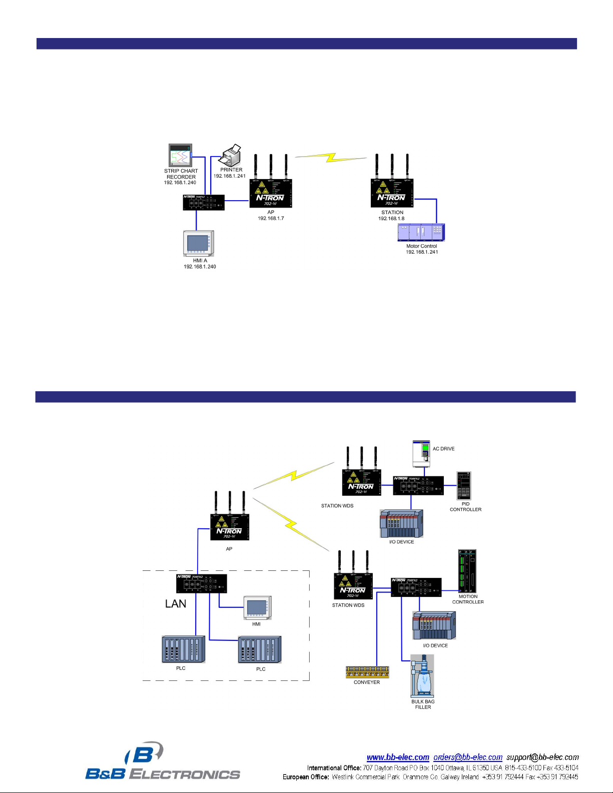
Station:
In "station" confi guration, the 702-W is
used to connect a single device (MAC
address) to a wireless access point.
Scenario 2 – Control Network
In station WDS mode, the 702-W can be connected to a remote wired Ethernet switch with multiple devices connected to the switch.
www.n-tron.com
Page 3

Scenario 3 – WDS Peering
702-W
These 702-W wireless radios have been confi gured as peers. This topology allows forklifts, or other mobile wireless devices, to maintain communication as they move
from the area covered by one 702-W into the area covered by the next 702-W.
Scenario 4 – Broadband Modem Wireless Router (W/ DHCP)
The 702-W confi gured as a powered router allows Layer 3 routing to setup network segmentation. It supports the Network Address Translation (Masquerading) feature
which is widely used by access points. NAT will act as the fi rewall between LAN and WLAN networks. Additional fi rewall settings can be confi gured for Layer 3 packet
fi ltering and access control in router mode. It can also act as a DHCP server, automating the assigning of IP addresses.
www.n-tron.com
Page 4

702-W
SPECIFICATIONS
Physical
Height: (w/o antennas): 5.2" (13.2 cm)
Width: 7.4" (18.8 cm)
Depth (includes DIN-Rail mount): 1.5" (3.9 cm)
Weight (max): 1.9 lbs (0.9 kg)
DIN-Rail Mount: 35 mm
Environmental
Operating Temperature: -40oC to 70oC
Storage Temperature: -40
Operating Humidity: 5% to 95% (non condensing)
Operating Altitude: 0 to 10,000 ft.
N-TRON Power Supply: NTPS-24-1.3 (sold separately)
Electrical
Redundant Input Voltage: 20-49 VDC (regulated)
Input Current (max): 200 mA max @ 24 VDC
702-W Max Power: 4.8 watts max
Input Ripple: Less than 100 mV
Reliability
MTBF: >1 million hours
Network Media
10BaseT: ≥Cat3 cable
100BaseTX: ≥Cat5 cable
802.11abgn: Air
Connectors
10/100BaseTX: One (1) RJ-45 copper port; PoE-powered device support
802.11abgn: (3) RP-SMA connectors
Recommended Wiring Clearance (Antenna Dependent)
Front: 4" (10.2 cm)
Side: 4" (10.2 cm)
Top: 6" (15.3 cm)
o
C to 85oC
Radio Output Power:
Up to 250mW US
802.11a 5GHz
DataRate Avg TX ±2dB
1-24Mbps 24 dBm
36Mbps 22 dBm
48Mbps 20 dBm
54Mbps 19 dBm
802.11b/g 2.4GHz
DataRate Avg TX ±2dB
1-24Mbps 24 dBm
36Mbps 22 dBm
48Mbps 20 dBm
54Mbps 19 dBm
802.11n 2.4GHz 5GHz
DataRate Avg TX ±2dB
MCS0 24dBm 24dBm
MCS1 24dBm 24dBm
MCS2 24dBm 24dBm
MCS3 22dBm 22dBm
MCS4 22dBm 22dBm
MCS5 22dBm 22dBm
MCS6 18dBm 18dBm
MCS7 15dBm 15dBm
MCS8 24dBm 24dBm
MCS9 24dBm 24dBm
MCS10 22dBm 22dBm
MCS11 20dBm 20dBm
MCS12 20dBm 20dBm
MCS13 17dBm 17dBm
MCS14 17dBm 17dBm
MCS15 15dBm 15dBm
Radio Receiver Sensitivity:
802.11a 5GHz
DataRate Sens. ±3dB
1-24Mbps -96 dBm
36Mbps -95 dBm
48Mbps -94 dBm
54Mbps -91 dBm
802.11b/g 2.4GHz
DataRate Sens. ±3dB
1-24Mbps -97 dBm
36Mbps -90 dBm
48Mbps -86 dBm
54Mbps -84 dBm
802.11n 2.4GHz 5GHz
DataRate Sens. ±3dB
MCS0 -97dBm -96dBm
MCS1 -96dBm -95dBm
MCS2 -93dBm -92dBm
MCS3 -91dBm -90dBm
MCS4 -87dBm -86dBm
MCS5 -84dBm -83dBm
MCS6 -78dBm -77dBm
MCS7 -75dBm -74dBm
MCS8 -96dBm -95dBm
MCS9 -94dBm -93dBm
MCS10 -91dBm -90dBm
MCS11 -88dBm -87dBm
MCS12 -85dBm -84dBm
MCS13 -80dBm -79dBm
MCS14 -79dBm -78dBm
MCS15 -76dBm -75dBm
Regulatory Approvals
• Safety: UL 508 and 1604
• Hazardous Location: Class I, Div 2, Groups A, B, C, D, T4A;
ANSI/ISA-12.12.01-2007
• EMI: FCC/CE (CFR 47, Part 15, Subpart B - Class A); ANSI C63.4;
• EMC: R&TTE Directive 99/5/EC ; EN 301 489-3; IEC 61000-4-2 (ESD);
IEC 61000-4-3 (RS)
• GOST-R Certifi ed
• ROHS compliant
www.n-tron.com
Designed to comply with:
IEEE 1613 for Electric Utility Substations
NEMA TS1/ TS2 for Traffi c Control
Page 5

702-W
www.n-tron.com
Page 6

702-W
ORDERING INFORMATION
PART NUMBER DESCRIPTION
702-W ........................................................1 Port (10/100BaseTX) Industrial Wireless Radio with three MIMO antennas, DIN-rail
702-W-PM ................................................. Panel mount kit for use with N-Tron's 702-W Wireless Radio
ANT-CAB-400-N-RPSMA-X ...................... Low loss CA-400 coaxial cable with (1) RP-TNC connector and (1) N-male connector
ANT-CAB-195-RPSMA-RPSMA-X ............ 702-W antenna bulkhead extension cable set; each cable includes (1) straight RP-SMA bulkhead jack and
(1) 90° RP-SMA plug (package of 3)
ANT-MD24-12 ............................................ 2.4GHz 12dBi mini directional antenna and pole mount bracket included
ANT-PAD24-16 ..........................................2.4GHz 16dBi panel directional antenna and pole mount bracket included
ANT-PAD58-19 ..........................................5.8GHz, 19dBi panel directional antenna N-female connector and pole mount bracket included
ANT-PD58-32 ............................................5.8 GHz parabolic dish 32dBi directional antenna and pole mount bracket included
ANT-LA6-NFF ............................................ 2-6GHz quarter wave lightning arrestor (N-female to N-female, less than 0.2dB insertion loss, IP65, -40° to 85°C)
ANT-CAB-400-N-X .................................... Low loss CA-400 coaxial cable with (2) N-female connector (for use with the ANT-LA6-NFF lightning arrestor)
NTPS-24-1.3 ............................................. DIN-rail power supply 24 VDC @ 1.3 amp
 Loading...