

Page 1
THE INDUSTRIAL NETWORK COMPANY
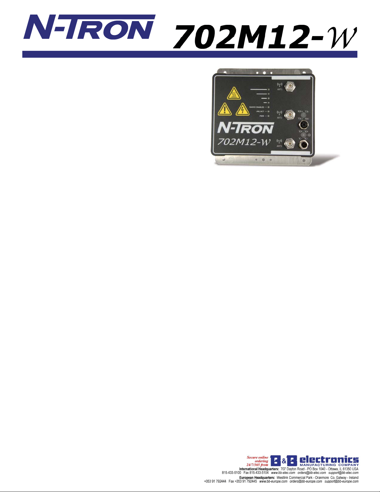
The N-TRON
outstanding performance and ease of use. It is ideally suited for
connecting wireless devices to a wired network or for connecting
two wired networks in an IP67 environment, where it is not possible,
impractical, or too expensive to install cable.
® 702M12-W Industrial Wireless Radio offers
Product Features
• Full IEEE 802.11a,b,g,n Compliance
• IP67 Rated, Industrial Hardened Enclosure
• One 10/100BaseTX M12 Port
• Three Antennas for 3x3 MIMO Operations
• Four user defi nable LED's for display of signal quality
• Radio Enable, Link/Activity, and power LEDs
• 802.3af PoE Powered Device
• Extended Environmental Specifi cations
• Autosensing 10/100BaseTX, Duplex, and MDIX
• Redundant Power Inputs (20-49 VDC)
• Web Browser Management
Wireless Compliance:
• IEEE 802.11a/b/g/n Compliant
Security:
• 802.11i with AES-CCM & TKIP Encryption
• 802.1x, 64/128 bit WEP
Data Rates:
• Legacy 802.11a/b/g (1-54Mbps),
• 802.11n (up to 300Mbps)
Range Performance:
• Indoor (Antenna Dependent) greater than 300m
• Outdoor (Antenna Dependent) greater than 60km
Applications
In industrial environments, the installation of fi ber or Cat5e cable
and associated power cables is diffi cult or cost prohibitive. There
are also applications which require communication with mobile
devices such as laptop computers, forklifts, cockpits or control
centers on mobile equipment such as cranes, and other devices
which are impossible to connect with copper or fi ber cable. The
N-TRON 702M12-W provides a wireless connection that can
be quickly and easily deployed. With it's wide operating
temperature range and 1 million hours MTBF, the 702M12-W
offers the industrial ruggedness that customers have come to
expect of N-TRON products. The IP67 sealed enclosure insures
that outdoor, wash down, and the most dusty environments will
present no problems to the 702M12-W. Three antennas enable the
use of Multiple-In, Multiple-Out (MIMO) technology for increased
throughput. Power over Ethernet (PoE) technology allows the
702M12-W to receive power through the Cat5e cable from a PoE
sourcing device, such as the N-TRON 105TX-POE Switch. This
eliminates the need for power cables or power supplies for the
702M12-W . Using wireless and PoE technology makes temporary
deployment of network nodes much easier because only one Cat5e
cable is required.
Industrial Packaging and Specifi cations
The 702M12-W is specifi cally designed to operate in industrial
environments. With it's rugged enclosure and industrial specifi cations
such as extended shock and vibrations specs plus redundant power
inputs, the 702M12-W easily meets and exceeds the operating
parameters of the connected equipment.
Multiple Wireless Modes
The 702M12-W provides a number of confi guration options that
allow it to be customized to suit specifi c application requirements.
Station: In "station" confi guration the 702M12-W is used to connect
a single device (MAC Address) to a wireless access point.
Station, WDS (Wireless Distribution System): In "station, WDS"
mode the 702M12-W can be connected to a remote wired switch
and will allow multiple devices (MAC Address forwarding) to be
connected to the wireless access point with WDS activated.
Access Point: The "Access Point" mode allows the 702M12-W to
serve as a wireless switch for the attached wireless stations. Wireless
access points are commonly used to create one wireless local area
network (WLAN) that spans an area around the Access Point. Each
access point typically supports up to 253 stations.
Access Point, WDS (Wireless Distribution System): The
702M12-W in "Access Point, WDS" mode allows wireless
connection of a number of access points to extend the coverage of
the wireless network. The main base Access Point in WDS mode
is extended using a series of relay Access points in WDS mode
(Extended Service Set) and can in turn form a WLAN consisting of
thousands of stations. All stations should be confi gured in "Station
WDS" mode. Correctly confi gured switches using WDS will create
a single network, providing station mobility throughout the wireless
network.
Multiple Network Modes
Bridge: In this mode the 702M12-W will operate in Layer two
without network segmentation.
Router: Router operating mode offers Layer three routing to allow
network segmentation.
Page 2
THE INDUSTRIAL NETWORK COMPANY
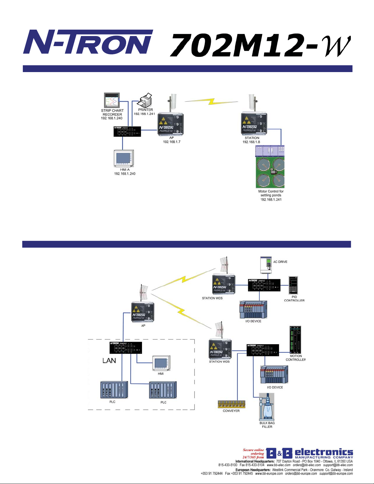
Scenario 1 – Basic Bridge
Access Point:
The "Access Point" mode
allows the
702M12-W
to serve as a wireless
switch for the wireless
stations attached to it.
In "station" confi guration
the
connect a single device
(MAC Address) to a
wireless access point.
Station:
702M12-W is used to
For added security, the 702M12-W supports WEP, WPA™, and WPA2™. WPA and WPA2, TKIP (Temporal Key Integrity
Protocol) and CCMP (Counter Mode with Cipher Block Chaining Message Authentication Code Protocol) are available.
Scenario 2 – Control Network
In Station WDS mode the 702M12-W can be connected to a remote wired Ethernet switch with multiple devices connected
to the switch.
Page 3

THE INDUSTRIAL NETWORK COMPANY
Scenario 3 – WDS Peering
In this scenairio, each 702M12-W has been confi gured as a peer of selected other 702M12-W(s) by using the MAC
Addresses of the select unit(s). This allows forklifts or other mobile wireless devices to maintain communication
seamlessly as they move from the area covered by one 702M12-W into the area covered by the next 702M12-W.
Scenario 4 – Broadband Modem Wireless Router (W/ DHCP)
The N-TRON 702M12-W confi gured as a router can act as a DHCP server and supports the Network Address T ranslation
(Masquerading) feature which is widely used by Access Points. This automates the assigning of IP addresses to devices as
they connect. NAT will act as a fi rewall between LAN and WLAN networks. Additional fi rewall settings can be confi gured
for layer 3 packet fi ltering and access control in Router mode.
Page 4

THE INDUSTRIAL NETWORK COMPANY
702M12-W Specifi cations
Case Dimensions
Height: (w/o antennas) 6.7" (17.2 cm)
Width: 6.7" (17.2 cm)
Depth: 1.8" (4.6 cm)
Weight (max): 3.5 lbs (1.6 kg)
Environmental
Operating Temperature: -40oC to 70oC
o
Storage Temperature: -40
C to 85oC
Operating Humidity: 5% to 100%
(Non Condensing)
Operating Altitude: 0 to 10,000 ft.
N-TRON Power Supply: NTPS-24-1.3
Electrical
Redundant Input Voltage: 20-49 VDC (Regulated)
Input Current (max): 200mA max @24 VDC
702M12-W Max Power: 4.8Watts max
Input Ripple: Less than 100mV
Reliability
MTBF: >1 Million Hours
Network Media
10BaseT: >Cat3 Cable
100BaseTX: >Cat5 Cable
802.11abgn: Air
Connectors
10/100BaseTX: One (1) M12 Copper Port
PoE Powered device support
802.11abgn (3) RP-TNC connectors
Radio Output Power:
Up to 250mW US
802.11a 5GHz
DataRate Avg TX ±2dB
1-24Mbps 24 dBm
36Mbps 22 dBm
48Mbps 20 dBm
54Mbps 19 dBm
802.11b/g 2.4GHz
DataRate Avg TX ±2dB
1-24Mbps 24 dBm
36Mbps 22 dBm
48Mbps 20 dBm
54Mbps 19 dBm
802.11n 2.4GHz 5GHz
DataRate Avg TX ±2dB
MCS0 24dBm 24dBm
MCS1 24dBm 24dBm
MCS2 24dBm 24dBm
MCS3 22dBm 22dBm
MCS4 22dBm 22dBm
MCS5 22dBm 22dBm
MCS6 18dBm 18dBm
MCS7 15dBm 15dBm
MCS8 24dBm 24dBm
MCS9 24dBm 24dBm
MCS10 22dBm 22dBm
MCS11 20dBm 20dBm
MCS12 20dBm 20dBm
MCS13 17dBm 17dBm
MCS14 17dBm 17dBm
MCS15 15dBm 15dBm
Radio Receiver Sensitivity
802.11a 5GHz
DataRate Sens. ±3dB
1-24Mbps -96 dBm
36Mbps -95 dBm
48Mbps -94 dBm
54Mbps -91 dBm
802.11b/g 2.4GHz
DataRate Sens. ±3dB
1-24Mbps -97 dBm
36Mbps -90 dBm
48Mbps -86 dBm
54Mbps -84 dBm
802.11n 2.4GHz 5GHz
DataRate Sens. ±3dB
MCS0 -97dBm -96dBm
MCS1 -96dBm -95dBm
MCS2 -93dBm -92dBm
MCS3 -91dBm -90dBm
MCS4 -87dBm -86dBm
MCS5 -84dBm -83dBm
MCS6 -78dBm -77dBm
MCS7 -75dBm -74dBm
MCS8 -96dBm -95dBm
MCS9 -94dBm -93dBm
MCS10 -91dBm -90dBm
MCS11 -88dBm -87dBm
MCS12 -85dBm -84dBm
MCS13 -80dBm -79dBm
MCS14 -79dBm -78dBm
MCS15 -76dBm -75dBm
Recommended Wiring Clearance (Antenna Dependent)
Front: 4" (10.16cm)
Side: 4" (10.16cm)
Top: 6" (15.24cm)
Contact Information
N-TRON Corp. N-TRON Asia N-TRON Europe GmbH
820 S. University Blvd., Suite 4E Suite #: 2267, 22/F, One Lujiazui Alte Steinhauserstr 19
Mobile, AL 36609 USA 68 Yin Cheng Road Center, 6330 Cham / Zg Switzerland
TEL: (251) 342-2164 Pudong New Area TEL: +41 41 7406636
FAX: (251) 342-6353 200120 Shanghai, P.R. China FAX: +41 41 7406637
Website: www.N-TRON.com Phone: +86 (0) 21 6194 6777
Email: N-TRON_info@N-TRON.com Fax: +86 (0) 21 6194 6699
® 2010 N-TRON, Corp. N-TRON and the N-TRON logo are trademarks of N-TRON, Corp. Product names mentioned herein are for identifi cation purposes only and
may be trademarks and/or registered trademarks of their respective company. Specifi cations subject to change without notice. The responsibility for the use and application
of N-TRON products rests with the end user. N-TRON makes no warranties as to the fi tness or suitability of any N-TRON product for any specifi c application. N-TRON Corporation
shall not be liable for any damage resulting from the installation, use, or misuse of this product.
UL /cUL Class I, Div 2, Groups A, B, C, D, and T4A
ANSI/ISA-12.12.01-2007 and UL 508 and 1604
FCC/CE (CFR 47, Part 15, Subpart B - Class A),
EN 301 489-3, IEC 6100-4-2, 6100-4-3,
R&TTE Directive 99/5/EC, ANSI C63.4, and ICES-003 Issue 3
GOST-R Certifi ed, RoHS Compliant,
Designed to comply with:
IEEE 1613 for Electric Utility Substations
NEMA TS1/ TS2 for Traffi c control
REV 100924
Printed in USA.
Regulatory Approvals
Page 5

THE INDUSTRIAL NETWORK COMPANY
702M12-W WIRELESS ETHERNET RADIO Cables with M12 connectors
Ordering Information Ordering Information
702M12-W Industrial Wireless Radio CAT5E-M12-M12-X Straight M12 to Str. M12, Shielded
702M12-PK Pole mount kit for 702M12-W CAT5E-M12-RJ45-X Straight M12 to RJ-45, Shielded
ANT-CAB-400-N-RPTNC-X Low Loss Coaxial Antenna cable
1 RP-TNC and 1 N Male connector
ANT-MD24-12 2.4GHz 12dBi Mini Directional Antenna CAT5E-RM12-M12-X 90º M12 to Str. M12, Shielded
ANT-PAD24-16 2.4GHz 16dBi Directional Antenna CAT5E-RM12-RM12-X 90º M12 to 90º M12, Shielded
ANT-PAD58-19 5.8GHz 19dBi Directional Antenna CAT5E-RM12-RJ45-X 90º M12 to RJ-45, Shielded
ANT-PD58-32 5.8 GHz Parabolic Dish 32dBi
Directional Antenna
ANT-LA6-NFF 2-6GHz quarter wave lightning arrestor
(N-female to N-female, less than 0.2dB
insertion loss, IP65, -40 to 85°C)
ANT-CAB-400-N-X Low loss CA-400 coaxial cable with
(2) N Female connectors for use with the
ANT-LA6-NFF lightning arrestor
M12DRC-ISO DIN-Rail kit, two isolated plastic clips Where:X = length of cable, fi ll in desired amount in feet.
M12DRC-MTL DIN-Rail kit, two metal clips
CAT5E-M12-X Straight M12 to bare end, Shielded
CAT5E-RM12-X 90º M12 to bare end, Shielded
PWR-M12-A-X Power Cable, M12 A-Coded Straight
Female to bare end, Shielded
PWR-RM12-A-X Power Cable, M12 A-Coded
90º Female to bare end, Shielded
Example: CAT5E-RM12-10 (for a 10ft cable)
NTPS-24-1.3 DIN-Rail Power Supply 24V@1.3 Amp
® 2010 N-TRON, Corp. N-TRON and the N-TRON logo are trademarks of N-TRON, Corp. Specifi cations subject to change without notice. Printed in USA.
 Loading...